Herunterladen Inhalt Inhalt Diese Seite drucken

Werbung

Verfügbare Sprachen

Verfügbare Sprachen

1:18 SCALE 4WD ELECTRIC MICRO PRO CRAWLER

Werbung

Inhaltsverzeichnis
loading

Inhaltszusammenfassung für Absima CR-18 PRO

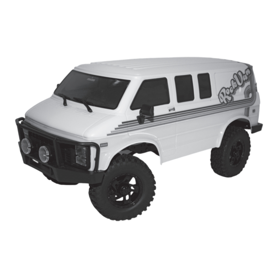
  • Seite 1 1:18 SCALE 4WD ELECTRIC MICRO PRO CRAWLER...
  • Seite 2: Vorsichtsmaßnahmen

    Benutzer müssen sich mit den Betriebsbedingungen des Senders vertraut machen um die Anforderungen an die HF-Exposition zu erfüllen. • Hiermit erklärt Absima, dass die beiliegende Funkanlage mit der RED 2014/53/EU übereinstimmt. • ACHTUNG: ES BESTEHT EXPLOSIONSGEFAHR, WENN DIE BATTERIE ODER DAS LADEGERÄT DURCH EINEN FALSCHEN TYP ERSETZT WIRD.
  • Seite 3: Sender Übersicht

    Sender Übersicht [12] [13] [14] [15] [10] [16] [17] [11] [18] Lenkrad (maximale Drehung beträgt 35° [10] Lenkung D/R (ST.D/R) von der Mitte nach links und rechts) Gashebel (maximaler Ausschlag 12.5° von [11] Gashebel D/R (TH.D/R) der Mitte nach links und rechts) Wahlschalter für die elektrische Knopf (CH4) [12]...
  • Seite 4 Sender Übersicht Installation der Batterien Batterietyp: AAA Einlegen der Batterien: 1. Öffnen Sie das Batteriefach 2. Legen Sie 4 vollgeladene AAA Batterien in das Fach ein. Achten Sie auf guten Kontakt. 3. Verschließen Sie das Batteriefach Low Volt Alarm: Wenn die Batterien unter 4.2V fallen, beginnt die G-LED langsam zu blinken.
  • Seite 5 Kalibration: Diese Funktion wird verwendet, um die Neutralstellung für Gas und Rad einzustellen. Jeder Sender wird vor dem Verlassen des Werks kalibriert, falls jedoch eine Neukalibrierung erforderlich ist, gehen Sie bitte wie folgt vor. Beachten Sie bitte die folgenden Schritte: 1.
  • Seite 6: Spezifikation

    Spezifikation Temperaturbereich: -10℃ ~ +60℃ Datenausgabe: PWM Produktname: FS-R4A3-BS Adaptive Sender: FS-MG43-BS Luftfeuchtigkeitsgrenze: 20%~95% Adaptive Modelle: 1:18 Fahrzeuge Wasserdicht: PPX4 Anzahl von Kanälen: 4 Entfernung: >150m(Bodenabstand ohne Inferenz) Anzahl der Lichter: 7 Online-Aktualisierung: NEIN RF: 2.4GHz ISM Abmessungen: 33*30*12mm (ohne Kondensator) 2.4G Protokoll: 2A-BS Gewicht: 11g Antenne: Einzelne Antenne...
  • Seite 7: Laden Der Lipo Batterie

    Lichtmodus des Fahrtenreglers Sollten Sie Ihr Fahrzeug mit mehr LEDs aufrüsten wollen, stehen Ihnen die folgenden Modi durch den Fahrtenregler zur Verfügung: Die Lichtsteuerung dient in erster Linie dazu, die Umschaltung von Beleuchtungszuständen und Beleuchtungsarten durch die Einstellung des Senders zu realisieren. Dieser Empfänger ist mit fünf Modi für die Steuerung von Modellautoscheinwerfern voreingestellt.
  • Seite 8 Da die Einhaltung der Bedienungsanleitung, sowie der Betrieb und die Bedingungen zur Verwendung des Produktes zu keiner Zeit von der Absima GmbH überwacht werden kann, übernimmt die Absima GmbH keinerlei Haftung für Schäden, Kosten, Verluste, die sich aus falscher Handhabung und/oder fehlerhaften Betrieb ergeben oder in irgendeiner Weise damit zusammenhängen.
  • Seite 9: Erklärung Fahrtenregler

    Erklärung Fahrtenregler 1. Anschließen der zugehörigen Ausrüstung: Stellen Sie sicher, dass der Regler vor dem Anschluss ausgeschaltet ist. Verbinden Sie den Motor mit M+ und M- des Reglers. Schließen Sie das Lenkservo an die mit "ST oder CH1" gekennzeichnete 3Pin-Schnittstelle des Reglers an (- + S beachten).
  • Seite 10: Batterie Sicherheitsmaßnahmen

    Batterie Sicherheitsmaßnahmen VOR DEM GEBRAUCH UNBEDINGT LESEN LADEN Verwenden Sie Ladegeräte und Einstellungen, die mit dem Akku, den Sie laden kompatibel sind (NiMH, LiPo...). Bei LiPo Akkus unbedingt Ladegerät mit Balancer-Funktion verwenden Wir empfehlen für alle Akkus einen Ladestrom von maximal 1C (z.B.
  • Seite 11 RF exposure compliance. • Hereby, [ Absima GmbH ] declares that the Radio Equipment [FS-MG41] is in compliance with RED 2014/53/EU. • The full text of the EU DoC and Appendix 1 of the FCC Statement are available at the following internet address: www.Absima.com...
  • Seite 12 Transmitter Overview [12] [13] [14] [15] [10] [16] [17] [11] [18] Wheel Angle, the maximum rotation of the steering wheel is 35 degrees from center to [10] Steering D/R (ST.D/R) left or right (CH1) Throttle trigger, has a total throw of 12 degrees, 12.5 degrees forward, and 12.5 [11] Throttle D/R (TH.D/R)
  • Seite 13: Basic Operations

    finish in 10s, The receiver will quit bind mode automatically. This binding information only applies to the attached receiver on the product, different receivers may require a different pocedure to complete the binding process. Product information is updated regularly, please visit our website: www.absima.com for more informations.
  • Seite 14 Stick Calibration This function is used to set the neutral position for throttle and wheel. Every transmitter is calibrated before leaving the factory, however if recalibration is required, please follow these steps: 1. Turn and hold the wheel as far clockwise as it will turn, hold the throttle all the way forward, then turn on the transmitter in calibration mode.
  • Seite 15 Specifications Data Output: PWM Product Name: FS-R4A3-BS Temperature Range: -10℃ ~ +60℃ Adaptive Transmitters: FS-MG43-BS Humidity Limit: 20%~95% Adaptive Models : 1:18 simulation cars, climbing cars WaterProof: PPX4 Number of Channels: 4 Distance: >150m(Ground distance without inference) Number of Lights: 7 Online Update: NO RF: 2.4GHz ISM Dimensions: 33mm*30mm*12mm (Excluding capacitor)
  • Seite 16: Charging The Battery

    Car light control The car light control is mainly to implement the changeover of lighting states and lighting modes by the setting of the transmitter. This receiver is preset with five modes for controlling model car lights. In each mode, the on/off states of backup lights are consistent;...
  • Seite 17 Disclaimer Since Absima GmbH cannot at any time monitor the observance of the operating instructions as well as the operation and conditions of use of the product, Absima GmbH does not assume any liability for damages, costs, losses resulting from incorrect handling and/or incorrect operation or in any way related thereto.
  • Seite 18 ESC function instructions 1. Connect related equipment: • Make sure the ESC is off before connection. Connect the motor with M+ and M- of ESC. Connect the steering servo to the 3Pin interface marked with "ST" of ESC (- + S connected correspondingly). Connect the battery with the positive and negative poles of ESC correspondingly.
  • Seite 19: Battery Warning

    Battery Warning READ CAREFULLY BEFORE USE STORE Use chargers and settings that are compatible with the battery you are charging (NiMH, LiPo ...). Always use a charger with balancer function for LiPo batteries. We recommend a maximum charge current of 1C for all batteries (e.g.
  • Seite 20: Précautions D'emploi

    RF. • Par la présente, Absima déclare que l'équipement radio ci-joint est conforme à la RED 2014/53/UE. • ATTENTION : IL Y A UN RISQUE D'EXPLOSION SI LA BATTERIE OU LE CHARGEUR EST REMPLACÉ...
  • Seite 21: Aperçu De La Télécommande

    Aperçu de la télécommande [12] [13] [14] [15] [10] [16] [17] [11] [18] Volant (la rotation maximale est de 35° du [10] Direction D/R (ST.D/R) centre vers la gauche et la droite) Levier d'accélération (débattement maximal [11] Accélérateur D/R (TH.D/R) de 12,5°...
  • Seite 22 Aperçu de la télécommande Installation des piles Type de piles : AAA Mise en place des piles : 1. ouvrez le compartiment des piles 2. insérez 4 piles AAA entièrement chargées dans le compartiment. Veillez à ce qu'elles soient bien en contact. 3.
  • Seite 23 Le calibrage Cette fonction est utilisée pour régler la position neutre des gaz et de la roue. Chaque émetteur est étalonné avant de quitter l'usine, mais si un réétalonnage est nécessaire, veuillez suivre la procédure suivante. Veuillez suivre les étapes suivantes : 1.
  • Seite 24 Spécification Aperçu Sortie de données : PWM Nom du produit : FS-R4A3-BS Relier Plage de température : -10℃ ~ +60℃ Émetteur adaptatif : FS-MG43-BS Limite d'humidité : 20%~95 Modèles adaptatifs : Véhicules 1:18 • Étanchéité : PPX4 Nombre de canaux : 4 Distance : >150m(distance au sol sans inférence) Nombre de lumières : 7 Mise à...
  • Seite 25: Charge De La Batterie

    Mode d'éclairage du régulateur de vitesse Si vous souhaitez équiper votre véhicule de plus de LED, les modes suivants sont disponibles grâce au régulateur de vitesse : La commande d'éclairage sert en premier lieu à réaliser la commutation des états et des types d'éclairage grâce au réglage de l'émetteur.
  • Seite 26 à la valeur de la facture du produit Absima impliqué dans l'événement. Ceci ne s'applique pas dans la mesure où nous devons assumer une responsabilité illimitée en raison de dispositions légales obligatoires ou de négligence grave.
  • Seite 27 Explication du régulateur de vitesse 1. brancher l'équipement associé : Assurez-vous que le régulateur est éteint avant de procéder au raccordement. Connectez le moteur à M+ et M- du régulateur. Connectez le servo de direction à l'interface 3 broches du régulateur marquée "ST ou CH1" (- + S à respecter). Connectez la batterie au régulateur de vitesse.
  • Seite 28 Mesures de sécurité pour la batterie LIRE ATTENTIVEMENT AVANT L'UTILISATION STORE Utilisez des chargeurs et des réglages compatibles avec la batterie que vous chargez (NiMH, LiPo ...). Utilisez toujours un chargeur avec fonction d'équilibrage pour les batteries LiPo Nous recommandons un courant de charge maximum de 1C pour toutes les batteries (par exemple, un courant de charge de 4A pour une batterie de 4000mAh) DEMANDE La batterie doit être bien protégée contre les influences extérieures et les...
  • Seite 29 Sub-Assembly Diagrams REDUCTION GEAR BOX 1010113 1010115 1010115 1010114 1010006 1010115 1010006 1010114 1010114 1010122 1010115 1010113 1010037 1010006 1010037 1010122 1010122 1010101 1010099 1010103 1010099 1010102 1010104 Front Portal 1010095 1010108 1010108 1010111 1010106 1010095 1010114 1010115 1010114 1010107 1010109 1010115 1010100...
  • Seite 30 Sub-Assembly Diagrams FRONT AXLE 1010112 1010115 1010095 1010107 1010114 1010107 1010115 1010112 1010115 1010105 1010112 1010114 1010097 1010115 1010114 1010095 1010115 1010115 1010100 1010112 1010107 REAR AXLE 1010100 1010107 1010115 1010114 1010115 1010111 1010109 1010110 1010095 1010115 1010107 1010106 1010114 1010111 1010114 1010107...
  • Seite 31 Main Chassis Installation...
  • Seite 32 Rock Van Body Installation 1010096 1010098 1010115 1010115 1010096 1010115 1010096 1010115 1010100 1010096 1010115 1010115 1010115 1010098 1010096 1010096 1010115 1010115 1010096 1010096 1010098 1010118 - Clear Lexan 1010119 - Grey 1010120 - Beige 1010115 1010100 1010115...
  • Seite 33 Rock Van Body Open 1010013 1010042 1010043 1010037 1010049 1010083 1KG High Torque 3wire Servo 7. 4 V 600MAH Lipo 55T High Torque Motor 7. 4 V USB Charger 4 Channel TX & ESC/RX 1010006 1010031 1010113 1010095 1010096 Main Drive Shaft Set & Rear Complete Vehicle Gear Set Transmission Gear Shaft Set Portal Hubs...
  • Seite 34 1010103 1010102 1010104 1010108 1010110 Tracking A/T Tire ( 1.2 ) Tyre foam ( 1.2 ) Tracking A/T Tire Set ( 1.2 ) Front CVD Drive Shaft Rear Axle Drive Shaft 1010107 1010106 1010111 1010109 1010112 Ball Stud set Metal Portal Gear Pins 1 x 4.5mm Portal axle Shaft Spindle Hub Busing...

Inhaltsverzeichnis