Vetus EAIR04024 Installationshandbuch
Inhaltsverzeichnis
Verfügbare Sprachen
Verfügbare Sprachen
Quicklinks
Installatiehandleiding
Installationshandbuch
Manuel d' installation
Manual de instalación
Manuale d'installazione
EAIR04024
Installation manual
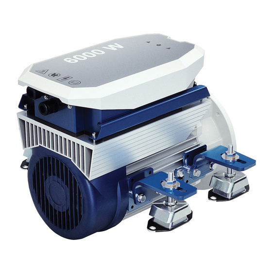
Air-cooled E-Air electric propulsion
Copyright © 2022 VETUS B.V. Schiedam Holland
Installationsvejledning
Installationsmanual
Installasjons handbook
Asennusopas
Instrukcja instalacji
4 kW 24 VDC
6
12
18
24
30
36
42
48
54
60
66
371101.11
Inhaltsverzeichnis

Verwandte Anleitungen für Vetus EAIR04024


Inhaltszusammenfassung für Vetus EAIR04024
- Seite 2 Zorg er voor dat de eigenaar van het schip over deze handleiding kan beschikken. Make sure that the user of the vessel is supplied with the owner’s manual. Sorgen Sie dafür, daß dem Schiffseigner die Gebrauchsanleitung bereitgestellt wird. Veillez à ce que le propriétaire du bateau puisse disposer du mode d’emploi. Asegurarse de que el propietario de la embarcación puede disponer de las instrucciones para el usuario.
- Seite 3 Inhoud Content Veiligheid Safety ..........
- Seite 5 Innhold Sisältö Sikkerhet Turvallisuus ......... . .
-
Seite 18: Deutsch
Schäden an der Anlage. Einleitung chtunG Dieses Handbuch enthält Richtlinien für die Installation eines luft- gekühlten VETUS E-Luft-Elektromotors (24 VGS, Typ 'EAIR04024' . Prüfen Sie sofort auf mögliche Leckagen nach dem Stapellauf des Schiffes. Die Qualität der Installation ist entscheidend für die Zuverlässig- keit des E-Air-Systems. -
Seite 19: Installationsformular
Um einen Garantieanspruch in Anspruch nehmen zu können, füllen Sie bitte das Installationsformularvollständig aus und senden Sie das Formular an: installationforms@vetus.com Die Seriennummer des MCV (VETUS Motorsteuerung) und des Mo- tors sind auf der Verpackung und in dieser Anleitung ersichtlich. Installation des Motors Motorraum Die Montagebügel sind leicht in der Höhe und im Winkel von 0°... -
Seite 20: Einbau Der Propellerwelle
Fahreigenschaften des Schiffes. Bei einem Boot mit elektrischem Antrieb ist es besonders wichtig, dass die Propellergröße richtig ge- wählt wird. Wenden Sie sich an Ihren VETUS-Händler, um den richtigen Propeller auszuwählen. Propellerblende Sie können sich sowohl für eine links- als auch für eine rechtsdre- hende Schraube entscheiden. -
Seite 21: Elektrisches System
- Installieren Sie die Batterien immer oberhalb des Bilgen Wasser- spiegels. VETUS kann wartungsfreie Batterien des Typs AGM (Absorbierte - Die Batterien müssen sicher befestigt werden, um eine Beschä- Glasmatte) liefern, die mit ca. 375 Ladezyklen bis zu einer Entladetie- digung des Gehäuses zu vermeiden. -
Seite 22: Hauptstromkabel
DEUTSCH Hauptstromkabel - Achten Sie darauf, dass die Kabel nicht mit scharfen Kanten in Be- rührung kommen. • Schalten Sie den Motor an die Batterien an wie in den Diagram- - Befestigen Sie die Kabel so, dass Verschleiß oder Abrieb durch Vi- men gezeigt, dafür siehe Seite 72. -
Seite 23: Interne Sicherung
DEUTSCH Interne Sicherung Anschließen von CAN-Bus (Steuerstrom)-Kabeln Im Anschlusskasten des Steuergeräts befindet sich eine interne Si- Siehe Diagramme von Seite wenn mehrere Schaltfelder anges- cherung. chlossen werden müssen. Diese Sicherung schützt die CAN-Bus-Steuerung des Wechselrichters. chtunG chtunG Die CAN-Bus-Spannungsversorgung muss immer an 12 Volt Ersetzen Sie eine defekte Sicherung immer durch eine (≥10 V, ≤16 V) angeschlossen werden. - Seite 72 Aansluitschema’s Schaltplan Diagrammes de câblage Wiring diagrams Diagramas de cableado Schemi Elettrici max. 80 A + 12 Volt + 24 Volt – 12 V 12 V 12 V 8 - 10 Nm (6 - 7 ft-lbf ) Boosted charge + 12 V - 24 V + 24 V 24 V...
- Seite 75 < = > < = > 12 V 12 V et op De CAN-bus is een keten waar de E-Air motor en panelen op zijn aan- The CAN bus is a chain to which the E-Air motor and panels are con- gesloten.
- Seite 77 1 E-Air motor (A/B) E-Air motor (A/B) E-Air Motor (A/B) 2 Bow thruster Bow thruster Bugstrahlruder 3 Motorbediening, motor (A/B) Motor control, motor (A / B) Motorsteuerung, Motor (A / B) 4 CAN-bus voeding CAN-bus supply CAN-Bus-Versorgung 5 Stuurstroomzekering Control voltage fuse Steuerspannungs-Sicherung 6 Aansluitkabel Connection cable...
- Seite 78 3(A) - 2 - -1(A)- 12 V Eén E-Air motor, één boegschroef, één stuurstand. Het Un motore E-Air, un'elica di prua, una postazione di schema kan worden uitgebreid tot maximaal vier stuur- comando. Il diagramma può essere esteso fino a quattro standen.
- Seite 79 1 E-Air motor (A/B) E-Air motor (A/B) E-Air Motor (A/B) 2 Bow thruster Bow thruster Bugstrahlruder 3 Motorbediening, motor (A/B) Motor control, motor (A / B) Motorsteuerung, Motor (A / B) 4 CAN-bus voeding CAN-bus supply CAN-Bus-Versorgung 5 Stuurstroomzekering Control voltage fuse Steuerspannungs-Sicherung 6 Aansluitkabel Connection cable...
- Seite 80 3(B) 3(A) - 2 - -1A- - 1B - 12 V Twee E-Air motoren, één boegschroef, twee stuurstanden. To E-Air motorer, en bovpropel, to rorstationer. Two E-Air motors, one bow thruster, two helm stations. Två E-Air-motorer, en bogpropeller, två roderstationer. Zwei E-Air Motoren, ein Bugstrahlruder, zwei Steuerpulte.
-
Seite 81: Hoofdafmetingen
1 E-Air motor (A/B) E-Air motor (A/B) E-Air Motor (A/B) 2 Bow thruster Bow thruster Bugstrahlruder 3 Motorbediening, motor (A/B) Motor control, motor (A / B) Motorsteuerung, Motor (A / B) 4 CAN-bus voeding CAN-bus supply CAN-Bus-Versorgung 5 Stuurstroomzekering Control voltage fuse Steuerspannungs-Sicherung 6 Aansluitkabel Connection cable... -
Seite 83: Akkukapasiteetti, Akkukaapelit
Accucapaciteit, accukabels Batteriets kapacitet, batterikabler Battery capacity, battery cables Batterikapacitet, batterikablar Batterikapasitet, batterikabler Akkukapazität, Akkukabel Capacité de la batterie, câbles de batterie Akkukapasiteetti, akkukaapelit Capacidad de las baterías, cables de baterías Pojemność akumulatora, kable akumulatora Capacità della batteria, e cavi della batteria Totale lengte plus- en minkabel EAIR 04024 Draaddoorsnede...