RSF Elektronik AK MS 25 Montageanleitung
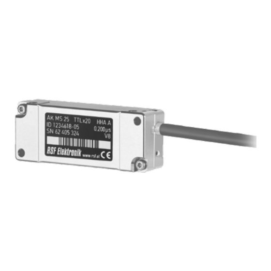
Abtastkopf
Vorschau ausblenden
Andere Handbücher für AK MS 25:
- Montageanleitung (9 Seiten) ,
- Montageanleitung (8 Seiten)

Verwandte Anleitungen für RSF Elektronik AK MS 25


Inhaltszusammenfassung für RSF Elektronik AK MS 25
- Seite 1 All manuals and user guides at all-guides.com MONTAGEANLEITUNG MOUNTING INSTRUCTIONS AK MS 25 Abtastkopf Scanning head Ausgabe 08/2020 Art.Nr. 1251532-01 Dok.Nr. D1251532-04-A-02 ...
-
Seite 2: Inhaltsverzeichnis
10 − 11 ..............Mounting possibilities 10 − 11 ................. Abschließende Arbeiten .................... Final steps ..................Testlauf, Betrieb ................Test running, operation ................Wartung, Reparatur ................Maintainance, repair ..........Demontage, Umweltschutz, Entsorgung ......... Demounting environmental protection, disposal AK MS 25... -
Seite 3: Konformität Mit Richtlinien / Directives Conformity
This signal word indicates important information that prevents NOTICE RSF Elektronik encoders fulfill the requirements of standard IEC 61010-1 only if the po- damage to property. wer is supplied from a secondary circuit with current limitation as per IEC 61010 3rd Ed. -
Seite 4: Technische Daten
A: Stahlband mit Goldteilung / Steel tape with gold grating 0.200µs: M: Stahlmaßband geschwärzt / Steel tape blackened Flankenabstand a (2% Tol.) AK MS 25: Produktname / Product name G: Chromteilung auf Glas / Chrome graduation on glass Edge separation a (2% tol.) - Seite 5 All manuals and user guides at all-guides.com Technische Daten / Technical data 2 2.2 ABMESSUNGEN / DIMENSIONS AK MS 25...
-
Seite 6: Sicherheitshinweise
Lay the cable from the scanning head to the control in such a way that it does not get caught up in operation when moving along the machine travel; it is not crushed, kinked or otherwise damaged; it does not run directly alongside power lines. AK MS 25... -
Seite 7: Zählrichtung / Counting Direction
Demands for mounting see in dimensions (see page 05). Referenzmarke Reference mark 4.3 STÖRQUELLEN / SOURCES OF INTERFERENCE Halten Sie den Mindestabstand von Störquellen ein. Keep minimum distance from sources of interference. ≤ 30 000 mm > 100 mm > 100 mm > 200 mm Störquellen Noise sources AK MS 25... -
Seite 8: Montage
5.1 GERÄT AUSPACKEN / UNPACK ENCODER 5.2 SCHUTZFOLIE ABZIEHEN / STRIP AWAY PROTECTIVE FOIL Beschädigungsgefahr durch spitzes Werkzeug! HINWEIS MONTAGEANLEITUNG MOUNTING INSTRUCTIONS AK MS 25 Abtastkopf Scanning head Die Abtastplatte ist hochsensibel und kann durch Kratzer beschädigt Ausgabe 07/2018 ... - Seite 9 Use the included gap foil. At loss use another plastic/polymer foil with a thickness of 0.75 mm. Entfernen Sie die Abstandsfolie nach Festziehen der Montageschrauben. Remove the gap foil after tighten the mounting screws. Max. 1,2 Nm AK MS 25...
-
Seite 10: Montagemöglichkeiten
All manuals and user guides at all-guides.com Montagemöglichkeiten / Mounting possibilities 6.1 MONTAGEMÖGLICHKEITEN AK MS 25 / MOUNTING POSSIBILITIES AK MS 25 6.2 MONTAGE AK ZU MAßVERKÖRPERUNG / MOUNTING AK TO GRADUATION CARRIER 6.2.1 MS 25 MK 6.2.2 MS 25 MP 6.2.3 MS 25 MT... - Seite 11 All manuals and user guides at all-guides.com Montagemöglichkeiten / Mounting possibilities 6 6.2.5 MS 25 BK 6.2.6 MS 25 BA = Kundenseitige Anschlussmaße / Required mating dimensions 6.2.7 MS 25 GK 6.2.8 MS 25 GA 6.2.9 MS 25 GS AK MS 25...
-
Seite 12: Abschließende Arbeiten
Connect the shield with the machine ground (field mass). Electrical short circuit! NOTICE The linear encoder is not protected against intrusion of intense contami- nation or water. Protect the linear encoder by applying a protective cover or similar. AK MS 25... -
Seite 13: Überprüfung Der Funktionen / Inspection Of Functions
Evaluation of counting signals via LED not active Steckerbelegung zu PWT 101 Funktionskontrolle Referenzimpuls RI Nur bei Überfahren der Referenzmarke Pinout adapter RSF Elektronik Function-control reference impulse RI Only by passing the reference mark standard connector pin assignment LED blinkt BLAU / LED blinks BLUE... -
Seite 14: Wartung, Reparatur
The linear encoders are not designed for self-modification or component replacement by the customer. Linear encoders from RSF Elektronik are designed for a long service life. Never open or modify the device yourself, as this will damage the device Preventive maintenance is not required. -
Seite 15: Demontage / Demounting
Observe the applicable country-specific regulations. Beachten Sie die Vorschriften des jeweiligen Landes. More detailed information on legal regulations can be obtained Genaue Informationen zu gesetzlichen Regelungen gibt from competent authorities. die zuständige Verwaltungsbehörde. AK MS 25... -
Seite 16: Elektronische Längen- Und Winkelmessgeräte, Präzisionsteilungen
All manuals and user guides at all-guides.com Ges.m.b.H. Elektronische Längen- und Winkelmessgeräte, Präzisionsteilungen Tarsdorf 93, 5121 Tarsdorf, Österreich +43 (0)6278 / 8192-0 +43 (0)6278 / 8192-58 e-mail: info@rsf.at internet: www.rsf.at Certified acc. to ISO 9001 ISO 14001 Ausgabe/Date 08/2020 Art.Nr. 1251532-01 Dok.Nr. D1251532-04-A-02 ...