HEIDENHAIN ERA 8480 Montageanleitung
Vorschau ausblenden
Andere Handbücher für ERA 8480:
- Montageanleitung (28 Seiten) ,
- Montageanleitung (27 Seiten)

Verwandte Anleitungen für HEIDENHAIN ERA 8480


Inhaltszusammenfassung für HEIDENHAIN ERA 8480
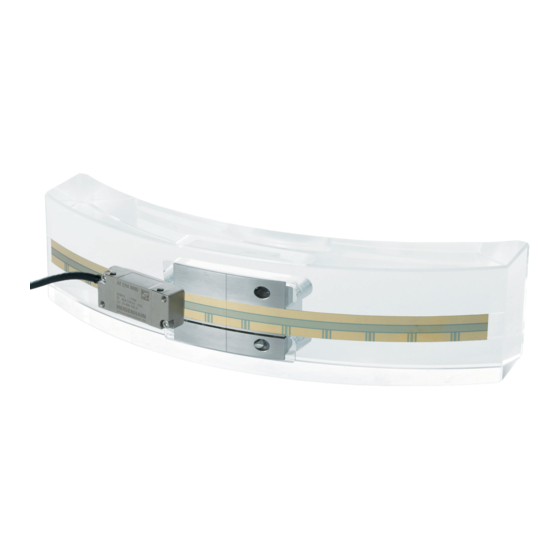
- Seite 1 Mounting Instructions Montageanleitung Instructions de montage Istruzioni di montaggio Instrucciones de montaje ERA 8480 ERA 8481 ERA 8482 7/2016...
- Seite 2 Contents Page Seite Inhalt 3 Warnings 3 Warnhinweise Sommaire 6 Items Supplied 6 Lieferumfang Indice 7 Mounting Information 7 Hinweise zur Montage Índice 10 Mounting the ERA 8400 C Scale Tape 10 Montage des Maßbandes ERA 8400 C 14 Mounting the ERA 8401 C Scale Tape 14 Montage des Maßbandes ERA 8401 C 15 Mounting the ERA 8402 C Scale Tape 15 Montage des Maßbandes ERA 8402 C...
- Seite 3 Warnings Warnhinweise Avertissement Avvertenze Advertencias Note: Mounting and commissioning is to be conducted by a qualified specialist under compliance with local safety regulations. Do not engage or disengage any connections while under power. The system must be disconnected from power. Achtung: Die Montage und Inbetriebnahme ist von einer qualifizierten Fachkraft unter Beachtung der örtlichen Sicherheitsvorschriften vorzunehmen.
- Seite 4 Do not drop the encoder or subject it to major vibration. Messgerät nicht fallen lassen oder größeren Erschütterungen aussetzen. Ne pas faire tomber l'appareil ou lui faire subir des secousses importantes. Non far cadere il sistema di misura né esporlo a eccessive vibrazioni. No dejar caer el sistema de medición ni someterlo a fuertes sacudidas.
- Seite 5 Do not bend or contaminate the scale tape! Maßband nicht knicken und verschmutzen! Ne pas plier ou salir le ruban de mesure! Non piegare e contaminare il nastro graduato! ¡No doblar ni ensuciar la cinta graduada! Clean the mounting surfaces with a lint-free cloth and spirit or isopropyl alcohol before mounting.
-
Seite 6: Items Supplied
Nastro graduato Cinta graduada ERA 8401 C ERA 8402 C AK ERA 8480 Scanning head with spacer foil and pin wrench Abtastkopf mit Abstandsfolie und Stiftschlüssel Tête captrice avec feuille de réglage et clef Allen Testina di scansione con pellicola distanziatrice e chiave per perni... -
Seite 7: Mounting Information
Mounting Information Hinweise zur Montage Remarques sur le montage Avvertenze per il montaggio Indicaciones para el montaje Leave space for fine adjustment! Auf Freiraum für Feinjustage achten! Prévoir une espace libre pour le réglage fin! Prestare attenzione alla libertà di movimento per la taratura di precisione! ¡Prever espacio libre para el ajuste fino! À... - Seite 8 Ensure that the edges are free of burrs! Auf gratfreie Kanten achten! Veiller à ce que les arêtes soient exemptes de bavures ! Prestare attenzione agli spigoli vivi! ¡Tener en cuenta que las aristas estén libres de rebaba! The contact surfaces *) must be clean! If required, clean them with a lint-free cloth and spirit or isopropyl alcohol.
- Seite 9 Ensure correct position of the reference mark (R) relative to the cable outlet (K). Auf die Lage der Referenzmarke (R) zu Kabelausgang (K) achten. Faire attention à la position de la marque de référence (R) par rapport à la sortie de câble (K). Prestare attenzione alla posizione dell'indice di riferimento (R) rispetto all'uscita cavo (K).
- Seite 10 Mounting the ERA 8400 C Scale Tape Montage des Maßbandes ERA 8400 C Montage du ruban de mesure ERA 8400 C Montaggio del nastro graduato ERA 8400 C Montaje de la cinta graduada ERA 8400 C Do not apply any adhesive to the butt joint Keinen Klebstoff am Maßbandstoß...
- Seite 11 Thin the adhesive layer (~ 0.01 mm). Kleber dünn abziehen (~ 0,01 mm). Egaliser une couche fine de colle (~ 0,01 mm). Lasciare uno strato sottile di colla (~ 0,01 mm). Retirar el pegamento de modo que quede una capa delgada (~ 0,01 mm). Insert the tensioning cleat.
- Seite 12 Insert the scale tape. Maßband einlegen. Poser le ruban de mesure. Inserire il nastro graduato. Poner la cinta graduada. Secure the scale tape with the tensioning cleat. Maßband mit Spannschloß befestigen. Fixer le ruban de mesure avec l'élément tendeur. Fissare il nastro graduato con l'elemento di tensionamento. Fijar la cinta graduada con el tensor.
- Seite 13 Remove adhesive residue. Final strength after approx. 12 hours at 20 °C (68 °F). If required, secure the tensioning cleat parts F during curing and check mounting by testing the signal quality. Kleberreste entfernen. Endfestigkeit nach ca. 12 Stunden bei ca. 20 °C. Gegebenenfalls während der Aushärtzeit die Spannschloßteile F fixieren und den Anbau durch die Überprüfung der Signalqualität kontrollieren.
- Seite 14 Mounting the ERA 8401 C Scale Tape Montage des Maßbandes ERA 8401 C Montage du ruban de mesure ERA 8401 C Montaggio del nastro graduato ERA 8401 C Montaje de la cinta graduada ERA 8401 C Spring Feder Ressort ISO 4762 M4x16 Molla Muelle Tighten the M4 screw enough that the part *) remains loose on both sides.
- Seite 15 Mounting the ERA 8402 C Scale Tape Montage des Maßbandes ERA 8402 C Montage du ruban de mesure ERA 8402 C Montaggio del nastro graduato ERA 8402 C Montaje de la cinta graduada ERA 8402 C ISO 7092 – 4 – 200HV – A2 For even distribution of tension in the scale tape, we recommend the ISO 7984 –...
- Seite 16 Dimensions of Scanning Head Anbaumaße Abtastkopf Dimensions de la tête captrice Dimensioni di collegamento della testina di scansione Dimensiones del cabezal palpador Á Ä Ã ISO 7092 – 3 – 200HV – A2 ISO 4762 – M3 – A2 (a+5)
- Seite 17 Ô Õ = Mounting options Ô Õ = Possibilità di montaggio = Bearing = Asse cuscinetti = Required mating dimensions = Dimensioni di collegamento lato cliente À = Mounting clearance (spacer foil) À = Distanza di montaggio (pellicola distanziatrice) Á = Distance between floor of scale-tape slot and threaded Á...
- Seite 18 Mounting the Scanning Head Montage Abtastkopf Ø 3.7 Montage de la tête captrice Montaggio della testina di scansione Montaje del cabezal palpador Ø 3.7 mm R 1 ‡ 8 mm R 2 ‡ 40 mm Gently press the scanning head against the spacer foil and the mounting surface and secure it with the screws provided.
- Seite 19 Other mounting option: Weitere Montagemöglichkeit: Autre possibilité de montage: Altra possibilità di montaggio: Otra posibilidad de montaje: Gently press the scanning head against the spacer foil and the mounting surface and secure it with the screws provided. Remove the spacer foil. Abtastkopf mit geringer Kraft gegen die Abstandsfolie und Anschraubfläche drücken und festschrauben.
- Seite 20 Check the resistance between the connector housing and the machine. Nominal value: < 1 Elektrischen Widerstand zwischen Steckergehäuse und Maschine prüfen. Sollwert: < 1 < 1 W Contrôler la résistance électrique entre le boîtier du connecteur et la machine. Valeur nominale : <...
- Seite 21 Inspection of Output Signals Prüfung der Ausgangssignale Contrôles des signaux de sortie Controllo dei segnali in uscita Comprobación de las señales de salida See operating instructions for PWT 1x, ID 319 502-9x Included with the PWT 18 siehe Betriebsanleitung PWT 1x, ID 319 502-9x im Lieferumfang PWT 18 enthalten voir le manuel d'utilisation du PWT 1x, ID 319 502-9x est inclus dans la fourniture du PWT 18...
- Seite 22 0.5 . . . 1 . . . 1.5 0.5 ..1 ..1.5 If the given adjustment values cannot be achieved, perform a fine adjustment or check the mounting tolerances and watch for contamination. Können die angegebenen Justagewerte nicht erreicht werden, Feinjustage durchführen bzw.
- Seite 23 Fine Adjustment of Scanning Head Feinjustage des Abtastkopfes Réglage fin de la tête captrice Taratura di precisione della testina di scansione Ajuste fino del cabezal palpador Loosen the screws one eighth of a turn (45°) to one sixth of a turn (60°). Adjustable at a torque of 0.1 Nm. 45°...
- Seite 24 The incremental signals and the reference-mark signals can be optimized by turning the eccentric nut (fine adjustment of the scanning field). Durch Drehen der Exzenterbuchse können die Inkremental- und Referenzmarkensignale optimiert werden (Feinjustage des Abtastfeldes). La rotation de la douille excentrique permet d'optimiser les signaux incrémentaux et les signaux des marques de référence (réglage fin du réticule).
- Seite 25 To adjust the position of the reference mark, turn the scanning head slightly. The peak of the reference mark signal should be in line with the peak of the composite signal. Make sure that the incremental signals do not decrease. Durch leichtes Verdrehen Referenzmarkenlage justieren.
- Seite 26 Tighten the screws. Do not exceed the max. tightening torque! Schrauben festziehen. Max. Anzugsmoment beachten! Serrer les vis. Attention au couple de serrage max.! Serrare le viti. Prestare attenzione alla coppia di serraggio massima! Apretar los tornillos. ¡Téngase en cuenta el par de apriete máximo! = 0.3 Nm + 0.1 Nm...
- Seite 27 Pin layout Anschlussbelegung 01 -H2 03S12-H2 02S12-H2 Raccordements Piedinatura Distribución del conector 12 10 A– B– R– BNGN WHGN The sensor line is connected inside the connector of the encoder to the supply line. Die Sensorleitung ist im Steckverbinder des Messgerätes mit der Versorgungsleitung verbunden. La ligne de retour (sensor) est reliée à...
- Seite 28 DR. JOHANNES HEIDENHAIN GmbH Dr.-Johannes-Heidenhain-Straße 5 83301 Traunreut, Germany { +49 8669 31-0 | +49 8669 32-5061 E-mail: info@heidenhain.de Technical support | +49 8669 32-1000 Measuring systems { +49 8669 31-3104 E-mail: service.ms-support@heidenhain.de TNC support { +49 8669 31-3101 E-mail: service.nc-support@heidenhain.de...