Inhaltsverzeichnis
Werbung
Verfügbare Sprachen
Verfügbare Sprachen
Quicklinks
Betriebsanleitung | Operating instructions | Notice d'instruction
Istruzioni per l'uso | Instrucciones de servicio | Bruksanvisning
R412026750-BAL-001-AE
2020-08, Replaces: 2020-04
DE/EN/FR/IT/ES/SV
AVENTICS™ AS3-SV
Sicherheitsventil
Safety valve
Distributeur de sécurité
Valvola di sicurezza
Válvula de seguridad
Säkerhetsventil
Werbung
Inhaltsverzeichnis
Fehlerbehebung

Verwandte Anleitungen für Emerson AVENTICS AS3-SV Serie


Inhaltszusammenfassung für Emerson AVENTICS AS3-SV Serie
- Seite 1 Betriebsanleitung | Operating instructions | Notice d’instruction Istruzioni per l'uso | Instrucciones de servicio | Bruksanvisning R412026750-BAL-001-AE 2020-08, Replaces: 2020-04 DE/EN/FR/IT/ES/SV AVENTICS™ AS3-SV Sicherheitsventil Safety valve Distributeur de sécurité Valvola di sicurezza Válvula de seguridad Säkerhetsventil...
-
Seite 2: Inhaltsverzeichnis
Inhaltsverzeichnis Anhang.............................................. Zu dieser Dokumentation ........................................Zusätzliche Dokumentation ......................................Gültigkeit der Dokumentation ......................................Erforderliche Dokumentationen......................................Darstellung von Informationen ......................................2.4.1 Warnhinweise ........................................2.4.2 Symbole..........................................Abkürzungen ............................................ Sicherheitshinweise........................................... Zu diesem Kapitel ..........................................Bestimmungsgemäße Verwendung....................................3.2.1 Sanftanlauf......................................... 3.2.2 Sicherheitsfunktion nach ISO 13849................................... Nicht bestimmungsgemäße Verwendung ..................................Qualifikation des Personals ....................................... - Seite 3 8.2.9 LED Anzeigen ........................................8.2.10 Sanftanlauf......................................... Pflege und Wartung .......................................... AS3-SV-Sicherheitsventil pflegen ...................................... AS3-SV-Sicherheitsventil warten ....................................... 10 Demontage und Austausch........................................ 10.1 AS3-SV demontieren......................................... 10.2 AS3-SV austauschen ......................................... 11 Entsorgung............................................12 Fehlersuche und Fehlerbehebung ...................................... 13 Ersatzteile und Zubehör........................................14 Technische Daten ..........................................AVENTICS™...
-
Seite 4: Anhang
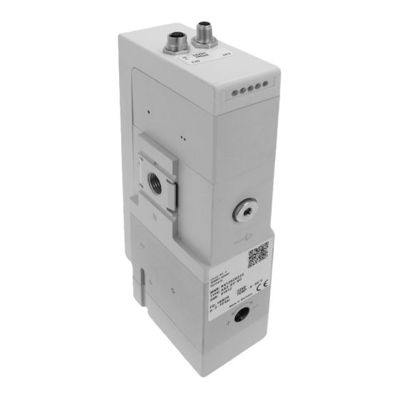
1 Anhang Abbildungen: Ansicht variiert je nach Serie. Abb. 1: Pneumatik-Schaltbild Abb. 4: Befestigung AS3-SV als einzelnes Ventil Abb. 2: Produktübersicht Abb. 5: Befestigung AS3-SV als Teil einer Wartungseinheit Abb. 3: Typenschild 24 V DC 0 V GND 1 Firmenname 2 Firmenadresse 3 Materialnummer 4 Typenbezeichnung 5 Seriennummer 6 Fertigungsdatum 7 Betriebsdruckbereich... - Seite 5 24 V DC 0V GND 24 V 41, 42 RUN-LED AS3 - SV Abb. 11: Signalfolge beim Einschalten Abb. 7: Prinzipielle Verdrahtung bei Ansteuerung PP 24 V 24 V DC 0 V GND 24 V AS3-SV Abb. 12: Signalfolge bei Ansteuerung PP Abb. 8: Prinzipielle Verdrahtung bei Ansteuerung NCNC 24 V DC 0 V GND 24 V...
-
Seite 6: Zu Dieser Dokumentation
2.4 Darstellung von Informationen 24 V 2.4.1 Warnhinweise In dieser Dokumentation stehen Warnhinweise vor einer Handlungsabfolge, bei der die Gefahr von Personen- oder Sachschäden besteht. Die beschriebenen 24 V Maßnahmen zur Gefahrenabwehr müssen eingehalten werden. Aufbau von Warnhinweisen SIGNALWORT AS3-SV Art und Quelle der Gefahr Folgen bei Nichtbeachtung Maßnahmen zur Gefahrenabwehr... -
Seite 7: Bestimmungsgemäße Verwendung
Diagnosedeckungsgrad (DC) 3.2 Bestimmungsgemäße Verwendung Die verwendeten Sicherheitsventile verfügen über eine Stellungsabfrage des Das AS3-SV-Sicherheitsventil ist ein Sicherheitsbauteil nach Maschinenrichtlinie Schiebers. Die Überwachung der Ventile beim Belüften und Entlüften bieten 2006/42/EG und daher mit dem CE-Kennzeichen versehen. Es dient bestim- einen hohen Diagnosedeckungsgrad der Steuerung (DC= 99 %). -
Seite 8: Produkt- Und Technologieabhängige Sicherheitshinweise
3.6 Produkt- und technologieabhängige Sicherheitshinweise 3.8 Pflichten des Betreibers Als Betreiber der Anlage, die mit einem AS3-SV-Sicherheitsventil ausgestattet WARNUNG werden soll, sind Sie dafür verantwortlich, Verletzungsgefahr durch gespeicherte Energie (Druckluft) und Spannung! • dass die bestimmungsgemäße Verwendung sichergestellt ist, Bei stillstehender Anlage bestehen weiterhin Gefahren durch gespeicherte •... -
Seite 9: Transport
1. Beenden Sie den Arbeitsbetrieb der Anlage und sichern Sie diese gegen Wie- 6.1 Transport dereinschalten. VORSICHT 2. Führen Sie alle schwebenden Lasten in eine statisch sichere Position zurück oder entfernen Sie diese von der Anlage. Verletzungsgefahr durch Herunterfallen! 3. Entlüften Sie gegebenenfalls gespeicherte Druckluft an Anlagenteilen im un- Das Sicherheitsventil kann bis zu 4185 g wiegen und beim Herunterfallen Per- mittelbaren Arbeitsbereich. -
Seite 10: Versorgungsspannung Anschließen
7.5.1 Versorgungsspannung anschließen Funktion S21 Taktsignal für S22 WARNUNG S22 Sicherheitseingang 2 Verletzungsgefahr! S11 Taktsignal für S12 Stromschlag durch falsches Netzteil! S12 Sicherheitseingang 1 1. Verwenden Sie zum Anschluss der Spannungsversorgung für das Ventil nc, nicht angeschlossen (not connect) einen 24-V-DC-SELV- oder PELV-Stromkreis nach DIN EN 60204-1. 2. -
Seite 11: Funktion „Belüften
1. Schalten Sie die pneumatische Versorgung ein. lüftet die Arbeitsleitung. Die LED OUT zeigt diesen Zustand durch langsames Blin- ken an. 2. Schalten Sie die 24-V-DC-Versorgungsspannung ein. Die Synchronzeit zur Überwachung der Signaleingänge ist 0,5 s. Der Zustand der Signaleingänge 1 und 2 wird durch die LED IN 1 und LED IN 2 angezeigt. 8.2.1 Funktion „Belüften“... -
Seite 12: Signalfolge Beim Auftreten Eines Fehlers
Wenn der zeitliche Abstand zwischen den Signaleingängen P und M größer als Farbe Anzeigeart Funktion die Synchronzeit zur Überwachung, verbleibt das AS3-SV-Sicherheitsventil im IN 2 grün leuchtet permanent Sicherheitseingang 2/M betätigt nicht aktivierten Zustand. In diesem Zustand (AS3-SV=0) entlüftet das AS3-SV-Si- IN 2 grün blinkt schnell Zeit für Synchronität überschritten... -
Seite 13: As3-Sv-Sicherheitsventil Warten
11 Entsorgung 9.2 AS3-SV-Sicherheitsventil warten Entsorgen Sie das AS3-SV-Sicherheitsventil nach den Bestimmungen Ihres WARNUNG Landes. Verletzungsgefahr bei Arbeiten an einer laufenden Anlage! Arbeiten bei laufender Anlage können zu schweren Verletzungen durch be- wegliche Maschinenteile führen. 12 Fehlersuche und Fehlerbehebung Bringen Sie die Anlage in einen Zustand, in dem keine Arbeitsbewegungen mehr durchgeführt werden. -
Seite 14: Ersatzteile Und Zubehör
ERR Fehlernum- ERR Fehlernum- Fehlererläuterung Abhilfe Elektrische Daten mer blinkt lang mer blinkt kurz elektrische Anschlüsse 1x Stecker und 1x Buchse, 5-pin, M12 Zeitüberwachung beim Schalldämpfer verstopft, Anzugsverzögerung < 150 ms Entlüften Schalldämpfer austau- schen Abfallverzögerung bei Nothalt: <10 ms undefinierter Pegel am Überprüfung der Signale bei Spannungsausfall: <10 s Eingang X2... - Seite 15 Contents Appendix............................................About this documentation......................................... Additional documents........................................Documentation validity ........................................Required documentation ........................................Presentation of information ......................................2.4.1 Warnings..........................................2.4.2 Symbols ..........................................Abbreviations............................................ Notes on safety..........................................About this chapter ..........................................Intended use ............................................. 3.2.1 Soft start ..........................................3.2.2 Safety Function According to ISO 13849 ................................Improper use ............................................
- Seite 16 8.2.9 LED displays ........................................8.2.10 Soft start ..........................................Care and maintenance ........................................Maintain the AS3-SV safety valve ...................................... Maintain the AS3-SV safety valve ...................................... 10 Disassembly and exchange ........................................ 10.1 Disassembling the AS3-SV ........................................ 10.2 Exchange the AS3-SV ........................................11 Disposal............................................. 12 Troubleshooting..........................................
-
Seite 17: Appendix
1 Appendix Figures: View varies according to the series. Fig. 1: Pneumatics wiring diagram Fig. 4: Mounting the AS3-SV as a single valve Fig. 2: Product overview Fig. 5: Mount the AS3-SV as part of a maintenance unit Fig. 3: Rating plate 24 V DC 0 V GND 1 Company name 2 Company address... - Seite 18 24 V DC 0V GND 24 V 41, 42 RUN-LED AS3 - SV Fig. 11: Signal sequence when switching on Fig. 7: Principle wiring for PP control 24 V 24 V DC 0 V GND 24 V AS3-SV Fig. 12: Signal sequence for PP control Fig. 8: Principle wiring for NCNC control 24 V DC 0 V GND...
-
Seite 19: About This Documentation
2.4 Presentation of information 24 V 2.4.1 Warnings In this documentation, there are warning notes before the steps whenever there is a risk of personal injury or damage to equipment. The measures described to 24 V avoid these hazards must be followed. Structure of warnings SIGNAL WORD AS3-SV... -
Seite 20: Intended Use
The following applications are therefore prohibited: 3.2 Intended use • Use in non-industrial applications/residential areas, The AS3-SV safety valve is a safety component in accordance with Machinery Di- • Outdoor use, rective 2006/42/EC and is therefore provided with the CE mark. Its intended use •... -
Seite 21: Personal Protective Equipment
5. Make sure that the basic and well-tried safety principles in accordance with WARNING ISO 13849 for implementation and operation of the component are complied with. Danger of injury by dismantling the safety valve 6. Make sure that the positive and negative test pulses for feedback-free opera- Pre-tensioned springs may suddenly be released when dismantling. -
Seite 22: Storage
6.2 Storage 7.3 Mount the pressure sensor or pressure gauge (optional) A pressure gauge or electronic pressure sensor can be connected to the thread NOTICE connection (8), see Fig. 2, once the blanking plug has been removed. Damage to the safety valve due to incorrect storage! Observe the mounting instructions enclosed with the components. -
Seite 23: Connect Start Input X2
7.5.7 Connect ground (FE, function potential compensation) WARNING A ground connection is available on the device. To discharge EMC interferences, Danger of injury due to valve malfunction! connect the FE connection (9), see Fig. 2, to the AS3-SV safety valve via a low-im- pedance line to functional earth. -
Seite 24: Signal Sequence For Ncnc Control
If the interval between signal inputs 1 and 2 is longer than the synchronization 8.2.7 Signal sequence for PM control time for monitoring, the AS3-SV safety valve remains in the non-activated state. The following signal sequence results during PM control of the AS3-SV safety In this state (AS3-SV=0) the AS3-SV safety valve exhausts the operating line and valve (see Fig. -
Seite 25: Soft Start
1. Check that all seals and plugs for the plug connections are firmly seated so Color Display type Function that no humidity can penetrate the AS3-SV safety valve during cleaning. Green Permanently illumi- The AS3-SV safety valve is ready 2. Only clean the AS3-SV safety valve using a slightly damp cloth. Only use water nated to do this and, if necessary, a mild detergent. -
Seite 26: Disposal
11 Disposal ERR error num- ERR error num- Explanation of errors Remedy ber flashes long ber flashes short Dispose of the AS3-SV safety valve in accordance with the currently applicable Undefined level on input Check the signals on plug regulations in your country. XPS and the wiring Undefined level on input Check the signals on plug... - Seite 27 Electrical data Time until ready for operation after switch on < 1.5 s Switching capacity of signal outputs 41–42: 24 V DC, 0.2 A Safety classification Directives 2006/42/EC (Machinery Directive) 2004/108/EC (EMC directive) Standards ISO 13849-1, IEC61508/IEC62061, DIN EN 61326-3-1 Test principle GS-IFA-M07, April 2017 Safety functions “Safe exhaust”...
- Seite 28 Sommaire Annexe .............................................. A propos de cette documentation...................................... Documentation supplémentaire ....................................... Validité de la documentation ......................................Documentations nécessaires ......................................Présentation des informations ......................................2.4.1 Mises en garde ........................................2.4.2 Symboles ........................................... Abréviations............................................Consignes de sécurité ........................................A propos de ce chapitre........................................Utilisation conforme .........................................
- Seite 29 8.2.9 Affichages LED ........................................8.2.10 Démarrage......................................... Entretien et maintenance ........................................Entretien du distributeur de sécurité AS3-SV..................................Maintenance du distributeur de sécurité AS3-SV................................10 Démontage et remplacement......................................10.1 Démontage du distributeur de sécurité AS3-SV ................................10.2 Remplacement du distributeur de sécurité AS3-SV ................................11 Mise au rebut.............................................
-
Seite 30: Annexe
1 Annexe Figures : la vue peut varier en fonction de la série. Fig. 1: Schéma de connexion pneumatique Fig. 4: Fixation du distributeur de sécurité AS3-SV en tant que distributeur indivi- duel Fig. 2: Vue d’ensemble des produits Fig. 5: Fixation du distributeur de sécurité AS3-SV en tant que composant d’une Fig. 3: Plaque signalétique unité... - Seite 31 24 V DC 0V GND 24 V 41, 42 RUN-LED AS3 - SV Fig. 11: Séquence de signal lors de la mise en marche Fig. 7: Câblage de principe pour la commande PP 24 V 24 V DC 0 V GND 24 V AS3-SV Fig. 12: Séquence de signal pour la commande PP Fig. 8: Câblage de principe pour la commande NCNC...
-
Seite 32: Propos De Cette Documentation
2.4 Présentation des informations 24 V 2.4.1 Mises en garde Dans la présente documentation, des consignes de danger figurent devant les instructions dont l’exécution recèle un risque de dommages corporels ou maté- 24 V riels. Les mesures décrites pour éviter des dangers doivent être respectées. Structure des consignes de danger MOT-CLE AS3-SV... -
Seite 33: Utilisation Conforme
Taux de couverture de diagnostic (DC) 3.2 Utilisation conforme Les distributeurs de sécurité utilisés possèdent une détection de position du ti- Le distributeur de sécurité AS3-SV est un élément de sécurité selon la directive roir. La surveillance des distributeurs par ventilation et purge offre un haut degré machine 2006/42/CE et porte par conséquent un marquage CE. -
Seite 34: Consignes De Sécurité Selon Le Produit Et La Technique
2. Toujours porter un casque anti-bruit durant le fonctionnement. 3.6 Consignes de sécurité selon le produit et la technique AVERTISSEMENT 3.8 Obligations de l’exploitant En tant qu’exploitant de l’installation devant être équipée d’un distributeur de sé- Risque de blessure dû à l’énergie emmagasinée (air comprimé) et à la ten- curité... -
Seite 35: Transport
6.1 Transport 7.1 Préparation du montage Préparer le montage comme suit : ATTENTION 1. Cesser toute activité de l’installation et la protéger de toute remise en marche Risque de blessures dû à une chute ! intempestive. Le distributeur de sécurité peut peser jusqu’à 4185 g et blesser des personnes 2. -
Seite 36: Raccordement De La Tension D'alimentation
7.5.1 Raccordement de la tension d’alimentation Broch Fonction AVERTISSEMENT S21 signal d’horloge pour S22 S22 entrée de sécurité 2 Risque de blessure ! S11 signal d’horloge pour S12 Risque d’électrocution dû à une alimentation électrique du réseau non S12 entrée de sécurité 1 conforme ! nc, non raccordé... -
Seite 37: Fonction « Ventiler
1. Mettre en marche l’alimentation pneumatique. La période de synchronisation pour la surveillance des entrées de signal est 0,5 s. L’état des entrées de signal 1 et 2 est affiché par les LED IN 1 et IN 2. 2. Brancher la tension d’alimentation de 24 V CC. Si l’écart temporel entre les entrées de signal 1 et 2 est supérieur à... -
Seite 38: Séquence De Signal En Cas De Défaut
Si, au moment 3, l’entrée de signal P n’est pas commandée à 24 V ou que l’entrée Cou- Type d’affichage Fonction de signal M n’est pas commandée à 0 V, le distributeur de sécurité AS3-SV passe leur à l’état non activé (AS3-SV=0) et purge la conduite de service. La LED OUT est IN 2 Verte Clignote lentement... -
Seite 39: Maintenance Du Distributeur De Sécurité As3-Sv
11 Mise au rebut 9.2 Maintenance du distributeur de sécurité AS3-SV Eliminer le distributeur de sécurité AS3-SV selon les directives en vigueur dans AVERTISSEMENT le pays d’utilisation. Risque de blessure dû à des travaux sur l’installation en fonctionnement ! Les travaux sur l’installation en cours de fonctionnement peuvent provoquer des blessures graves en raison des pièces de machine en mouvement. -
Seite 40: Pièces De Rechange Et Accessoires
Clignotement Clignotement Explication du défaut Remède Données électriques long du n° de bref du n° de dé- Résistance du câble Max. 40 Ω défaut ERR faut ERR Puissance absorbée 280 mA Surveillance du temps lors Silencieux bouché, rem- de la purge placer le silencieux Indice de protection selon CEI 60529/EN IP 65 (uniquement à... - Seite 41 Indice Appendice ............................................Sulla presente documentazione......................................Documentazione supplementare...................................... Validità della documentazione ......................................Documentazione necessaria ......................................Presentazione delle informazioni ...................................... 2.4.1 Avvertenze di sicurezza ...................................... 2.4.2 Simboli..........................................Abbreviazioni ............................................ Indicazioni di sicurezza ........................................Sul presente capitolo ........................................Utilizzo a norma ..........................................3.2.1 Avviamento dolce ......................................
- Seite 42 8.2.9 Indicatori LED ........................................8.2.10 Avviamento dolce ......................................Cura e manutenzione......................................... Cura della valvola di sicurezza AS3-SV ....................................Manutenzione della valvola di sicurezza AS3-SV ................................10 Smontaggio e sostituzione ........................................ 10.1 Smontaggio della AS3-SV........................................10.2 Sostituzione della AS3-SV........................................11 Smaltimento ............................................. 12 Ricerca e risoluzione errori......................................... 13 Parti di ricambio e accessori.......................................
-
Seite 43: Appendice
1 Appendice Figure: l'immagine varia in base alla serie. Fig. 1: Schema di collegamento pneumatico Fig. 4: Fissaggio della AS3-SV come valvola singola Fig. 2: Panoramica sul prodotto Fig. 5: Fissaggio AS3-SV come parte di un gruppo di trattamento Fig. 3: Targhetta di identificazione 24 V DC 0 V GND 1 Nome azienda 2 Indirizzo azienda... - Seite 44 24 V DC 0V GND 24 V 41, 42 RUN-LED AS3 - SV Fig. 11: Sequenza di segnali all'accensione Fig. 7: Cablaggio principale con comando PP 24 V 24 V DC 0 V GND 24 V AS3-SV Fig. 12: Sequenza di segnali nel comando PP Fig. 8: Cablaggio principale con comando NCNC 24 V DC 0 V GND...
-
Seite 45: Sulla Presente Documentazione
2.4 Presentazione delle informazioni 24 V 2.4.1 Avvertenze di sicurezza Nella presente documentazione determinate sequenze operative sono contras- segnate da avvertenze, indicanti un rischio di lesioni a persone o danni a cose. Le 24 V misure descritte per la prevenzione di pericoli devono essere rispettate. Struttura delle avvertenze di sicurezza PAROLA DI SEGNALAZIONE AS3-SV... -
Seite 46: Utilizzo A Norma
3.2 Utilizzo a norma 3.3 Utilizzo non a norma La valvola di sicurezza AS3-SV è un componente di sicurezza ai sensi della diretti- AVVERTENZA: va macchine 2006/42/CE ed è quindi contrassegnata con il marchio CE. È destina- In caso di uso scorretto sono possibili danni alle cose e alle persone. ta alla ventilazione e allo sfiato controllato all'interno di impianti ad aria compres- Sono quindi vietate le seguenti applicazioni: sa o di applicazioni simili nonché... -
Seite 47: Indicazioni Di Sicurezza Sul Prodotto E Sulla Tecnologia
3.6 Indicazioni di sicurezza sul prodotto e sulla tecnologia 3.8 Obblighi del gestore È responsabilità del gestore dell'impianto nel quale viene utilizzata una valvola di AVVERTENZA sicurezza AS3-SV Pericolo di lesioni dovute all'energia accumulata (aria compressa) e alla ten- • assicurare l’utilizzo a norma, sione! •... -
Seite 48: Trasporto
2. Portare tutti i carichi oscillanti in una posizione statica sicura oppure rimuo- 6.1 Trasporto verli dall'impianto. ATTENZIONE 3. Scaricare l'aria compressa eventualmente accumulata nelle parti dell'impianto nel campo di lavoro diretto. Pericolo di lesioni a causa di caduta! 4. Togliere l'alimentazione pneumatica ed elettrica dalle parti rilevanti dell'im- La valvola di sicurezza può... -
Seite 49: Collegamento Del Contatto Di Segnalazione
Utilizzando il comando NCNC o NCNO gli interruttori di sicurezza vengono ali- Per proteggere la tensione di esercizio si consiglia un salvavita tipo Z mentati dal segnale di clock (S21, S11). L'ingresso di sicurezza 1 (S12) viene colle- (max. 2 A) o un fusibile per correnti deboli (max. 1 A, ritardato). gato a S11 tramite l'interruttore. -
Seite 50: Sequenza Di Segnali All'accensione
8.2.3 Sequenza di segnali all'accensione zio. Il LED OUT è spento. Per aerare nuovamente, entrambi gli ingressi segnale 1 e 2 devono essere aperti/interrotti. I LED IN 1 e IN 2 in questo stato sono spenti. All'accensione della valvola di sicurezza AS3-SV si presenta la sequenza di segnali seguente (vedere fig.11). -
Seite 51: Indicatori Led
numero è possibile analizzare l'errore. Al tempo 4 l'apparecchio viene spento e farlo è necessario ruotare la vite di regolazione per la “funzione Soft start” (4), ve- l'errore corretto. Se l'apparecchio viene acceso al tempo 5 e l'errore è stato cor- dere fig. 2. retto, dopo l'autotest (7, ca. 1,5 s) sarà... -
Seite 52: Smontaggio E Sostituzione
3. Controllare regolarmente se tutti i connettori a spina sono inseriti saldamen- Disturbo Causa possibile Soluzione Il livello di pressione/portata La pressione di esercizio è Aumentare la pressione di 4. Stabilire gli intervalli di manutenzione a seconda delle condizioni ambientali e non viene raggiunto o dimi- troppo bassa esercizio... -
Seite 53: Parti Di Ricambio E Accessori
13 Parti di ricambio e accessori Classificazione di sicurezza Guasti per causa comune (Common Cau- > 65 Definizione Codice se Failure – CCF) Kit di interblocco per montaggio singolo R412007367 Grado di copertura diagnostica (DC) alto, 99% Kit di fissaggio per il montaggio di un gruppo di trattamento. R412026828 Numero cicli massimo 2/s, misurato senza volume... - Seite 54 Índice Anexo..............................................Acerca de esta documentación ......................................Documentación adicional ......................................... Validez de la documentación ......................................Documentación necesaria......................................... Presentación de la información ......................................2.4.1 Indicaciones de advertencia ....................................2.4.2 Símbolos ..........................................Abreviaturas ............................................. Indicaciones de seguridad........................................Acerca de este capítulo ........................................Utilización conforme a las especificaciones ..................................
- Seite 55 8.2.9 Indicadores LED........................................8.2.10 Arranque suave ........................................Cuidado y mantenimiento ......................................... Cuidado de la válvula de seguridad AS3-SV ..................................Mantenimiento de la válvula de seguridad AS3-SV ................................10 Desmontaje y sustitución ........................................10.1 Desmontaje de la AS3-SV ........................................10.2 Sustitución de la AS3-SV ........................................11 Eliminación de residuos ........................................
-
Seite 56: Anexo
1 Anexo Figuras: la vista varía en función de la serie. Fig. 1: Diagrama de conexiones neumáticas Fig. 4: Fijación de AS3-SV como válvula individual Fig. 2: Vista general de productos Fig. 5: Fijación de AS3-SV como parte de una unidad de preparación de aire Fig. 3: Placa de características 24 V DC 0 V GND... - Seite 57 24 V DC 0V GND 24 V 41, 42 RUN-LED AS3 - SV Fig. 11: Secuencia de señales al conectar Fig. 7: Cableado principal en caso de pilotaje PP 24 V 24 V DC 0 V GND 24 V AS3-SV Fig. 12: Secuencia de señales en caso de pilotaje PP Fig. 8: Cableado principal en caso de pilotaje NCNC 24 V DC 0 V GND...
-
Seite 58: Acerca De Esta Documentación
2.4 Presentación de la información 24 V 2.4.1 Indicaciones de advertencia En esta documentación hay indicaciones de advertencia previas a cada acción que conlleve peligro de daños materiales o personales. Se deben respetar las me- 24 V didas descritas de protección ante peligros. Estructura de las indicaciones de advertencia PALABRA DE ADVERTENCIA AS3-SV... -
Seite 59: Utilización Conforme A Las Especificaciones
3. Entregue el producto a terceros siempre junto con la documentación necesa- Grado de cobertura de diagnóstico (DC) ria. Las válvulas de seguridad usadas disponen de una consulta de posición de la co- rredera. La supervisión de las válvulas durante la presurización y la purga ofrecen 3.2 Utilización conforme a las especificaciones un elevado grado de cobertura diagnóstica del control (DC= 99 %). -
Seite 60: Indicaciones De Seguridad Según Producto Y Tecnología
3.6 Indicaciones de seguridad según producto y tecnología 3.8 Obligaciones del explotador Como explotador de la instalación equipada con una válvula de seguridad AS3-SV ADVERTENCIA es responsable de que: Peligro de lesiones por tensión y energía (aire comprimido) acumuladas! • el producto se utilice conforme a las especificaciones, Aunque la instalación esté... -
Seite 61: Transporte
1. Finalice el funcionamiento de la instalación y asegure esta para que no se vuel- 6.1 Transporte va a conectar. ATENCIÓN 2. Desplace todas las cargas en suspensión a una posición segura o retírelas de la instalación. Peligro de lesiones por caída! 3. -
Seite 62: Conexión De La Tensión De Alimentación
7.5.1 Conexión de la tensión de alimentación Función S21 señal de pulso para S22 ADVERTENCIA S22 entrada de seguridad 2 Peligro de lesiones! S11 señal de pulso para S12 Descarga de corriente por uso de bloque de alimentación erróneo! S12 entrada de seguridad 1 1. -
Seite 63: Función "Presurizar
8.2.1 Función “Presurizar” El tiempo de sincronización para la supervisión de las entradas de señal es de 0,5 s. El estado de las entradas de señal 1 y 2 se muestra mediante el LED IN 1 y el Si la válvula de seguridad AS3-SV debe presurizar las máquinas, debe conectar LED IN 2. -
Seite 64: Secuencia De Señales En Caso De Aparición De Un Error
purga el conducto de trabajo y el LED OUT no se ilumina. El LED IN 1 y el LED IN 2 Color Tipo de indicación Función parpadean rápidamente y muestran que las entradas de señal 1 y 2 no se pilotan IN 2 Verde encendido de forma Entrada de seguridad 2/M accionada... -
Seite 65: Mantenimiento De La Válvula De Seguridad As3-Sv
11 Eliminación de residuos 9.2 Mantenimiento de la válvula de seguridad AS3-SV Elimine la válvula de seguridad AS3-SV de acuerdo con las especificaciones de ADVERTENCIA su país. Peligro de lesiones al trabajar en una instalación en marcha! Si se interviene en la instalación mientras esta está en marcha, se corre el ries- go de sufrir lesiones graves debido a las piezas móviles de la máquina. -
Seite 66: Piezas De Repuesto Y Accesorios
El número de El número de Explicación del error Remedio Datos eléctricos error ERR parpa- error ERR parpa- Tensión 24 V DC +/-10 % dea de forma dea brevemente prolongada Tensión de alimentación Bloque de alimentación/Suministro eléctrico Supervisión temporal du- Establecer una presión mí- Bloque de alimentación SELV según DIN EN rante la purga nima de 2 bar en el puer-... - Seite 67 Innehåll Bilaga ..............................................Om denna dokumentation ........................................ Ytterligare dokumentation ....................................... Dokumentationens giltighet ......................................Nödvändig dokumentation ....................................... Återgivning av information ....................................... 2.4.1 Varningsinformation ......................................2.4.2 Symboler..........................................Förkortningar............................................ Säkerhetsföreskrifter......................................... Om detta kapitel ..........................................Avsedd användning........................................... 3.2.1 Mjukstart..........................................3.2.2 Säkerhetsfunktion enligt ISO 13849 ................................... Ej avsedd användning........................................
- Seite 68 8.2.9 LED-indikeringar......................................... 8.2.10 Mjukstart..........................................Skötsel och underhåll ........................................Rengöra AS3-SV-säkerhetsventil ....................................... Underhålla AS3-SV-säkerhetsventil ....................................10 Demontering och byte........................................10.1 Demontera AS3-SV ........................................... 10.2 Byta ut AS3-SV ..........................................11 Avfallshantering ..........................................12 Felsökning och åtgärder ........................................13 Reservdelar och tillbehör ........................................14 Tekniska data ............................................
-
Seite 69: Bilaga
1 Bilaga Bild: Vy varierar beroende på serie. Bild 1: Pneumatik-kopplingsschema Bild 4: Fäste AS3-SV som enkel ventil Bild 2: Produktöversikt Bild 5: Fäste AS3-SV som en del av en luftbehandlingsenheten Bild 3: Typskylt 24 V DC 0 V GND 1 Tillverkarnamn 2 Tillverkarens adress 3 Materialnummer 4 Typbeteckning 5 Materialnummer... - Seite 70 24 V DC 0V GND 24 V 41, 42 RUN-LED AS3 - SV Bild 11: Signalsekvens vid inkoppling Bild 7: Grundläggande ledningar vid styrning PP 24 V 24 V DC 0 V GND 24 V AS3-SV Bild 12: Signalföljd vid styrning PP Bild 8: Grundläggande ledningar vid styrning NCNC 24 V DC 0 V GND 24 V...
-
Seite 71: Om Denna Dokumentation
2.4 Återgivning av information 24 V 2.4.1 Varningsinformation I denna dokumentation står säkerhetsanvisningar före en handlingsföljd där det finns risk för person- eller materialskador. De åtgärder som beskrivs för att 24 V avvärja faror måste följas. Varningsanvisningarnas uppbyggnad SIGNALORD AS3-SV Typ av fara eller riskkälla Följder om faran inte beaktas Åtgärder för att avvärja faran... -
Seite 72: Avsedd Användning
Följande användning är därmed förbjuden: 3.2 Avsedd användning • användning i icke-industriella miljöer/bostäder Säkerhetsventilen AS3-SV är en säkerhetskomponent enligt maskindirektiv • användning utomhus, 2006/42/EG och har CE-märkning. Den är avsedd att användas för att kontrollera • användning utanför de angivna gränser för produkten som finns specificerade på- och avluftning i tryckluftsanläggningar eller jämförbara applikationer samt i Tekniska data för att undvika oavsiktlig start och aktivering av energi i pneumatiska... -
Seite 73: Personlig Skyddsutrustning
6. Kontrollera att de positiva och negativa av- och påkopplingsimpulserna, som VARNING görs oberoende av de pneumatiska produkterna respekteras (se „Tekniska data“). Risk för personskador vid isärmontering av säkerhetsventilen Förspända fjädrar kan plötsligt fjädra ut om ventilen monteras isär. Säkerhetsventilen får aldrig monteras isär. 4 Leveransomfattning VARNING •... -
Seite 74: Lagring
Observera monteringsanvisningarna som bifogas komponenterna. 6.2 Lagring OBS! 7.4 Ansluta pneumatiska anslutningar Förutsättning: Skador på säkerhetsventilen om den lagras felaktigt! Olämpliga lagringsförhållanden kan leda till att produkten korroderar och Försörjningstrycket måste alltid vara mellan 2 bar och10 bar. livslängden förkortas. Maximal lagringstid är två år. Om försörjningstrycket är mindre än 2 bar, garanteras inte korrekt 1. -
Seite 75: Ansluta Startingång X2
7.5.3 Ansluta startingång X2 8 Driftstart VARNING VARNING Risk för personskador! Risk för personskador vid arbeten på anläggningen! Användningen av funktionen ”automatisk start” i den mening som avses i IEC/ Om arbeten utförs på en anläggning som är i drift kan detta leda till svåra EN 60204-1 är endast tillåten tillsammans med andra lämpliga åtgärder för personskador på... -
Seite 76: Signalföljd Vid Styrning Ncnc
signalingångarna 1 och 2 vara på 0. LED IN 1 och IN 2 är avstängda i detta Vid tidpunkt 1 styrs signalingången M med 0 V. Om signalingången P styrs med tillstånd. 24 V inom synkroniseringstiden (4) går AS3-SV-säkerhetsventilen till påluftat läge vid tidpunkt 2 (AS3-SV=1). LED OUT tänds och indikerar aktiverat tillstånd. 8.2.5 Signalföljd vid styrning NCNC Synkroniseringstiden för övervakning (4) är 0,5 s. -
Seite 77: Mjukstart
AS3-SV-säkerhetsventilen är underhållsfri under normal drift. För att säkerställa Färg Indikeringstyp Funktion korrekt drift måste AS3-SV-säkerhetsventilen aktiveras minst en gång i månaden. IN 2 grön lyser permanent Säkerhetsingång 2/M aktiverad Aktivera AS3 SV-säkerhetsventilen minst en gång i månaden. IN 2 grön blinkar snabbt Tid för synkronisering överskriden... -
Seite 78: Reservdelar Och Tillbehör
Vid eventuella fel ska anslutningar, driftspänning och arbetstryck kontrolleras Demontera AS3-SV-säkerhetsventilen enligt kapitlet Demontering och byte i aktuell anläggningsdel. och skicka ventilen till AVENTICS GmbH. Adressen finns på baksidan av denna bruksanvisning. Ytterligare hjälp i samband med fel framgår av följande tabell: Möjlig orsak Åtgärd Tryck-/flödesnivån uppnås... - Seite 79 Säkerhetsklassificering Vibrationsbeständighet (DIN EN 60068-2-6) 0,35 mm ± 0,05 mm väg vid10 Hz–55 Hz Stötsäker (DIN EN 60068-2-27) 30 g vid18 ms varaktighet Stötvågform: Sinus-halvvåg Säkerhetsklassificering max kategori 4, PL e, SIL 3 Livslängd se B från AVENTICS SISTEMA biblioteket Felfunktion på grund av gemensam orsak >...
- Seite 80 The Emerson logo is a trademark and service mark of Emerson Electric Co. AVENTICS is a mark of Further addresses: one of the Emerson Automation Solutions family of business units. All other marks are property www.emerson.com/contactus...