
Verwandte Anleitungen für tuxhorn tubra-PGS XL


Inhaltszusammenfassung für tuxhorn tubra-PGS XL
- Seite 1 ® tubra -PGS XL (ohne Regelung) ® tubra -PGS-C XL (mit Regelung) Solarstation für Großanlagen Montage- und Bedienungsanleitung...
-
Seite 2: Inhaltsverzeichnis
Inhalt Einführung ........................3 Verwendungszweck ....................3 Sicherheitshinweise ....................3 Mitgeltende Unterlagen ....................3 Lieferung und Transport ..................... 3 Aufbau - Lieferumfang ....................4 Technische Daten ......................5 Allgemein ........................5 Abmessungen / Platzbedarf ..................6 Druckverlust / Pumpenkennlinien ................6 Montage ........................ -
Seite 3: Einführung
E i n f ü h r u n g Diese Anleitung beschreibt die Montage der Solarstation tubra ® -PGS (-C) XL sowie die Be- dienung und die Wartung. Lesen Sie diese Anleitung vor Beginn der Montagearbeiten sorgfältig durch. Bei Nichtbeachtung entfallen sämtliche Garantie- und Gewährleistungsansprüche. Die Anleitung richtet sich an ausgebildete Fachhandwerker, die entsprechende Kenntnisse im Umgang mit Heizungsanlagen, Wasserleitungsinstallationen und mit Elektroinstallationen haben. -
Seite 4: Aufbau - Lieferumfang
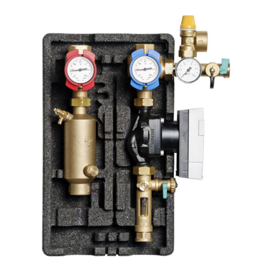
A u f b a u - L i e f e r u m f a n g ® -PGS XL tubra ® -PGS-C XL tubra Pos. Benennung Pos. Benennung Vorlauf-Kugelhahn mit integrierter Sicherungsfeder Schwerkraftbremse Rücklauf-Kugelhahn mit integrierter Zeigerthermometer Schwerkraftbremse Solarsicherheitsventil 6/10 bar Dämmung komplett... -
Seite 5: Technische Daten
T e c h n i s c h e D a t e n Allgemein ® Bezeichnung / Typ tubra -PGS XL Max. Kollektorfläche (Flachkollektor) 116 m² (Low Flow, 18 l/m²h) 70 m² (High Flow, 30 l/m²h) Nennleistung bei ΔT 12 K 35 kW Empfohlene Betriebsweise High-Flow (30 l/m²h) -
Seite 6: Abmessungen / Platzbedarf
Abmessungen / Platzbedarf Abmessungen und Mindestplatzbedarf für Montage und Wartungsarbeiten. Je nach bauseitiger Verrohrung erhöhten Platzbedarf beachten. ® ® -PGS XL -PGS-C XL tubra tubra Druckverlust / Pumpenkennlinien Art.-Nr. 977.25.02.00 Stand 06/2018 - 6 -... -
Seite 7: Montage
M o n t a g e Wandmontage Sicherungsfedern [11] herausziehen. Vorlauf- und Rücklaufstrang anheben und aus dem Montagewinkel [14] herausziehen. Hintere Dämmschale abnehmen. Befestigungspunkte des Montagewinkels [14] an der Wand anzeichnen und zwei Löcher ø10 mm bohren. Dübel setzen und Montagewinkel [14] mit den Schrauben und Unterlegscheiben festschrau- ben. -
Seite 8: Hydraulischer Anschluss
Hydraulischer Anschluss Bezeichnung Beschreibung Solarvorlauf Solarrücklauf Speichervorlauf Speicherrücklauf Beispieldarstellung, erhebt keinen Anspruch auf Voll- ständigkeit und ersetzt keine fachmännische Planung. Achtung! Zum Eindrehen der Anschlüsse am Solar- vorlauf- und Solarrücklauf-Kugelhahn die Griffe der Kugelhähne in Stellung „ge- schlossen“ drehen (Griffe stehen waage- recht). -
Seite 9: Elektrischer Anschluss
Elektrischer Anschluss 4.4.1 Allgemein Arbeiten an der elektrischen Anlage sowie das Öffnen von Elektrogehäusen darf nur in spannungsfreiem Zustand und nur von autorisiertem Fachpersonal durchgeführt werden. Bei den Anschlüssen auf richtige Klemmenbelegung und Polarität achten. Die Regelung und die elektrischen Bauteile vor Überspannung schützen. ®... -
Seite 10: Funktion Der Schwerkraftbremsen
F u n k t i o n d e r S c h w e r k r a f t b r e m s e n Die Schwerkraftbremsen sind jeweils im Vorlauf-[1] und Rücklauf-Kugelhahn [2] integriert. Die Betätigung erfolgt durch Drehung der Griffe der Kugelhähne. Betriebsstellung Zur Verhinderung der Schwerkraftzirkulation dürfen die Ventilteller nicht angelüftet sein. -
Seite 11: Durchflussmesser
D u r c h f l u s s m e s s e r Die Einstellung des Volumenstromes des Wärmeträgermediums erfolgt erst über die Einstellung der Drehzahlstufen der Um- wälzpumpe und dann über die Drossel [B] am Durchflussanzeiger. Der Durchflussmesser dient zur Anzeige Drossel [B] zur Einstellung des eingestellten Volumenstromes. -
Seite 12: Befüllen, Spülen Und Entleeren
B e f ü l l e n , S p ü l e n u n d E n t l e e r e n Befüllen Zum Befüllen der Solaranlage muss der Vorlauf- und Rücklaufkugelhahn [1, 2] in Stellung „Schwer- kraftbremse geöffnet“... -
Seite 13: Kontrollspülung
Kontrollspülung Schritt 1 Spindel [B] in Stellung „S“ drehen. Der Schlitz steht waagerecht, Abflachung nach links. Vorlaufkugelhahn [1] in Betriebsstellung, Rück- laufkugelhahn [2] in 45° Stellung. Befüllschlauch am KFE-Hahn [4a] anschließen. Entleerschlauch am KFE-Hahn [4b] anschließen. Die KFE-Hähne öffnen und die Kontrollspülung wie dargestellt durchführen. -
Seite 14: Regelung (Nur Bei Tubra®-Pgs-C Xl)
R e g e l u n g ( N u r b e i t u b r a ® - P G S - C X L ) Die Regelung ist vormontiert und vorverdrahtet. Die Kollektor- und Speicherfühler müssen noch angeschlossen bzw. verlängert werden. Bedienung Beachten Sie hierzu die Montage- und Bedienungsanleitung der verwendeten Regelung. -
Seite 15: Störungen / Fehlerbehebung
S t ö r u n g e n / F e h l e r b e h e b u n g Liegt eine Fehlermeldung vor, wird diese im Display der Regelung angezeigt. Bitte beachten Sie hierzu die entsprechende Anleitung der Regelung. Störung Mögliche Ursache Behebung... -
Seite 16: Pumpeninformation
P u m p e n i n f o r m a t i o n Logik PWM2 – Signal < 7 % Pumpe aus 7 - 12 % Min Drehzahl (Betrieb) 12 - 15% Min Drehzahl (start up) 15 - 95% Variable Drehzahl zwischen und n... - Seite 17 Art.-Nr. 977.25.02.00 Stand 06/2018 - 17 -...
- Seite 18 Art.-Nr. 977.25.02.00 Stand 06/2018 - 18 -...
- Seite 19 Art.-Nr. 977.25.02.00 Stand 06/2018 - 19 -...
- Seite 20 Händler Gebr. Tuxhorn GmbH & Co. KG • Senner Straße 171 • 33659 Bielefeld Tel.: +49 (0) 521 44808-0 • Fax: +49 (0)521 44808-44 • www.tuxhorn.de...
- Seite 21 ® tubra -PGS XL (without control unit) ® tubra -PGS-C XL (with control unit) Solar station for large systems Assembly and operating instructions...
- Seite 22 Content Introduction ........................3 Intended purpose ....................... 3 Safety instructions ..................... 3 Applicable documents ....................3 Delivery and transport ....................3 Construction - scope of delivery ..................4 Technical specifications ....................5 General instructions ....................5 Dimensions / required space ..................6 Pressure loss / pump characteristics ................
-
Seite 23: Introduction
I n t r o d u c t i o n ® This manual describes the installation process for the tubra -PGS (-C) XL solar station, as well as its operating and maintenance procedures. Read this manual carefully before starting any installation work. Non-compliance will invalidate all claims under the guarantee and warranty. -
Seite 24: Construction - Scope Of Delivery
C o n s t r u c t i o n - s c o p e o f d e l i v e r y ® tubra -PGS XL ® tubra -PGS-C XL Item Designation Item Designation Supply ball valve with integrated Locking spring Gravity brake... -
Seite 25: Technical Specifications
T e c h n i c a l s p e c i f i c a t i o n s General instructions ® Designation/type tubra -PGS XL Max. collector surface (flat plate collector) 116 m² (Low flow, 18 l/m²h) 70 m²... -
Seite 26: Dimensions / Required Space
Dimensions / required space Dimensions and minimum space required for assembly and maintenance work. Please note the increased amount of required space depending on the on-site piping. ® ® tubra -PGS XL tubra -PGS-C XL Pressure loss / pump characteristics Code no. -
Seite 27: Assembly
A s s e m b l y Wall-mounted assembly Remove the locking springs [11]. Lift the supply and return line and remove from the mounting bracket [14]. Remove the rear insulating shell. Mark the drilling points for the mounting bracket [14] on the wall and drill two x ø10 mm holes. -
Seite 28: Hydraulic Connection
Hydraulic connection Designation Description Solar supply line Solar return line Tank supply Tank return This is a sample illustration which does not claim to be exhaustive; it does not replace specialist planning. Attention! To close the connections of the solar flow and return ball valve, rotate the handles of the ball valves to the "closed"... -
Seite 29: Electrical Connections
Electrical connections 4.4.1 General instructions Only authorised, specialist personnel are permitted to open electrical housings and work on the electrical system after de-energising the equipment. When establishing connections, make sure the terminal assignments and polarity are correct. Protect the control unit and electrical components against excess voltage. -
Seite 30: Gravity Brake Function
G r a v i t y b r a k e f u n c t i o n The gravity brakes are integrated in the supply [1] and return ball valve [2]. The valves are operated by turning the ball valve handles. Operating position In order to prevent circulation under the force of gravity, the valve plates should not be... -
Seite 31: Flow Meter
F l o w m e t e r The flow rate of the heat transfer fluid is adjusted initially via the speed settings on the circulation pump and then via the throttle [B] on the flow indicator. The flow meter displays the set volume flow. Throttle [B] for adjusting the flow rate Read off the flow rate from... -
Seite 32: Filling, Flushing And Draining
F i l l i n g , f l u s h i n g a n d d r a i n i n g Filling In order to fill the solar system the supply and re- turn ball valve [1, 2] must be set to the "gravity brake open"... -
Seite 33: Check Flushing
Check flushing Step 1 Turn the spindle [B] to the "S" position. The slot is now horizontal, while the flat section points to the left. Set the supply ball valve [1] to the operating posi- tion; set the return ball valve [2] to a 45° setting. Connect the filling hose to the boiler filling and drain valve [4a]. -
Seite 34: Control Unit (For Tubra®-Pgs-C Xl Only)
C o n t r o l u n i t ( f o r t u b r a ® - P G S - C X L o n l y ) The control unit has been pre-assembled and pre-wired. The collector and storage sensors still require connecting/extended. -
Seite 35: Malfunctions / Troubleshooting
M a l f u n c t i o n s / t r o u b l e s h o o t i n g If an error message is output, it appears on the control unit display. Please observe the corresponding instructions for the control unit. -
Seite 36: Pump Information
P u m p i n f o r m a t i o n Logic PWM2 – Signal < 7 % Pump off 7 - 12 % Min. rotational speed (opera- tion) 12 - 15% Min. rotational speed (start 15 - 95% Variable rotational speed be- tween n... - Seite 37 Code no. 977.25.02.00 Dated 06/2018 - 17 -...
- Seite 38 Code no. 977.25.02.00 Dated 06/2018 - 18 -...
- Seite 39 Code no. 977.25.02.00 Dated 06/2018 - 19 -...
- Seite 40 Reseller Gebr. Tuxhorn GmbH & Co. KG • Senner Straße 171 • 33659 Bielefeld, Germany Tel.: +49 (0) 521 44808-0 • Fax: +49 (0)521 44808-44 • www.tuxhorn.de...
- Seite 41 ® tubra -PGS XL (senza dispositivo di regolazione) ® tubra -PGS-C XL (con dispositivo di regolazione) Stazione solare per grandi impianti Montage- und Bedienungsanleitung...
- Seite 42 Indice Introduzione ........................3 Scopo d'utilizzo ......................3 Avvertenze di sicurezza ..................... 3 Documentazione associata ..................3 Fornitura e trasporto ....................4 Struttura – Fornitura ....................... 4 Dati tecnici ........................5 Generale ........................5 Dimensioni / Ingombro ....................6 Caduta di pressione / Curve caratteristiche delle pompe ........... 6 Montaggio ........................
-
Seite 43: Introduzione
I n t r o d u z i o n e ® Le presenti istruzioni descrivono il montaggio della stazione solare tubra -PGS (-C) XL, il suo impiego e la sua manutenzione. Leggere attentamente le presenti istruzioni prima di iniziare i lavori di montaggio. La mancata osservanza di dette istruzioni farà... -
Seite 44: Fornitura E Trasporto
Fornitura e trasporto Verificare la completezza e l’integrità della merce immediatamente dopo il ricevimento. Co- municare immediatamente eventuali danni o reclami. S t r u t t u r a – F o r n i t u r a ®... -
Seite 45: Dati Tecnici
D a t i t e c n i c i Generale ® Descrizione / Tipo tubra -PGS XL Max. superficie di collettori (collettore piatto) 116 m² (Low Flow, 18 l/m²h) 70 m² (High Flow, 30 l/m²h) Potenza nominale con ΔT 12K 35 kW Modalità... -
Seite 46: Dimensioni / Ingombro
Dimensioni / Ingombro Dimensioni ed ingombro minimo per montaggio e lavori di manutenzione. A seconda della tubazione presente nell'edificio occorre badare ad un elevato fabbisogno di spazio. ® ® tubra tubra -PGS XL -PGS-C XL Caduta di pressione / Curve caratteristiche delle pompe N. -
Seite 47: Montaggio
M o n t a g g i o Montaggio a parete Estrarre le molle di sicurezza [11]. Estrarre dall'angolo di montaggio [14] il condotto di mandata e di riflusso. Rimuovere il guscio isolante posteriore. Segnare i punti di fissaggio dell'angolo di mon- taggio [14] sulla parete e creare due fori di ø10 Inserire i tasselli e fissare l'angolo di montaggio [14] servendosi delle viti e delle rondelle. -
Seite 48: Attacco Idraulico
Attacco idraulico Denominazi- Descrizione MANDSOL Mandata solare RITSOL Ritorno solare MANDSERB Mandata serbatoio RITSERB Ritorno serbatoio Illustrazione esemplificativa, non ha alcuna pretesa di completezza e non sostituisce la progettazione a regola d'arte. Attenzione! Per avvitare gli attacchi dei rubinetti a sfera di mandata solare e di riflusso solare girare le impugnature dei rubinetti a sfera in posizione "chiuso“... -
Seite 49: Allacciamento Elettrico
Allacciamento elettrico 4.4.1 Generale I lavori sull'impianto elettrico e l'apertura delle custodie dei componenti elettrici possono es- sere effettuati solamente a corrente elettrica scollegata e solo da personale specializzato opportunamente autorizzato. Negli attacchi verificare la corretta polarità e il corretto collegamento dei morsetti. -
Seite 50: Funzionamento Dei Freni Gravitazionali
F u n z i o n a m e n t o d e i f r e n i g r a v i t a z i o n a l i I freni gravitazionali sono rispettivamente integrati nel rubinetto di mandata [1] e riflusso [2]. L'azionamento avviene girando le impugnature dei rubinetti. -
Seite 51: Flussimetro
F l u s s i m e t r o L'impostazione della mandata del vettore termico avviene dapprima attraverso la re- golazione dei livelli del numero di giri della pompa di circolazione, poi tramite la farfal- la [B] dell'indicatore di flusso. Il flussimetro serve alla visualizzazione della Farfalla [B] per la rego- portata impostata. -
Seite 52: Travasare, Lavare E Svuotare
T r a v a s a r e , l a v a r e e s v u o t a r e Travasare Ai fini del travaso dell'impianto solare il rubinetto a sfera di mandata e riflusso [1, 2] deve trovarsi in posizione "Freno gravitazionale aperto“... -
Seite 53: Lavaggio Di Controllo
Lavaggio di controllo Passo 1 Portare l'asta [B] in posizione "S“. L'intaglio si trova in posizione orizzontale, lo spianamento è rivolto verso sinistra. Rubinetto a sfera di mandata [1] in posizione di funzionamento, rubinetto a sfera di riflusso [2] in posizione a 45°. -
Seite 54: Dispositivo Di Regolazione (Solo Per Tubra®-Pgs-C Xl)
D i s p o s i t i v o d i r e g o l a z i o n e ( s o l o p e r t u b r a ® - P G S - C X L ) Il dispositivo di regolazione è... -
Seite 55: Guasti / Risoluzione Dei Problemi
G u a s t i / r i s o l u z i o n e d e i p r o b l e m i Gli eventuali messaggi di errore vengono visualizzati sul display del dispositivo di rego- lazione. -
Seite 56: Informazioni Inerenti Alla Pompa
I n f o r m a z i o n i i n e r e n t i a l l a p o m p a Logica segnale PWM2 < 7 % Pompa spenta 7 - 12 % Numero di giri min. - Seite 57 N. art. 977.25.02.00 Ultimo aggiornamento 06/2018 - 17 -...
- Seite 58 N. art. 977.25.02.00 Ultimo aggiornamento 06/2018 - 18 -...
- Seite 59 N. art. 977.25.02.00 Ultimo aggiornamento 06/2018 - 19 -...
- Seite 60 Rivenditore Gebr. Tuxhorn GmbH & Co. KG • Senner Straße 171 • 33659 Bielefeld, Germania Tel.: +49 521 44808-0 • Fax: +49 521 44808-44 • www.tuxhorn.de...