tuxhorn tubra-nemux-S Montage- Und Bedienungsanleitung
Zubehör kaskadenverrohrung
Vorschau ausblenden
Andere Handbücher für tubra-nemux-S:
- Montage- und bedienungsanleitung (32 Seiten) ,
- Montage- und bedienungsanleitung (48 Seiten)
Inhaltsverzeichnis
Werbung
Verfügbare Sprachen
Verfügbare Sprachen
Quicklinks
Werbung
Inhaltsverzeichnis

Verwandte Anleitungen für tuxhorn tubra-nemux-S


Inhaltszusammenfassung für tuxhorn tubra-nemux-S
- Seite 1 ® tubra - nemux-S/M Zubehör Kaskadenverrohrung Montage- und Bedienungsanleitung...
-
Seite 2: Inhaltsverzeichnis
Inhalt Allgemeine Hinweise ................... 3 Verwendungszweck ..................3 Sicherheitshinweise ..................3 Mitgeltende Unterlagen ..................3 Aufbau ......................... 4 Lieferung und Transport ................... 4 Technische Daten ....................5 Abmessungen/Platzbedarf .................. 6 Montage und Installation ..................7 Hydraulischer Anschluss mit Zubehör ..............9 Elektrischer Anschluss .................. -
Seite 3: Allgemeine Hinweise
A l l g e m e i n e H i n w e i s e ® Diese Anleitung beschreibt die Montage der tubra -Kaskadenverrohrung der Frischwasserstation tubra®-nemux- S/M und ist nur gültig in Verbindung mit der Montage- und Bedienungsanleitung der Frischwasserstation tubra®-nemux- S/M. -
Seite 4: Aufbau
A u f b a u ® ® - Absperrset Kaskadenstation tubra -Kaskadenverrohrung tubra Pos. Bezeichnung Bezeichnung 8x 1“ Flachdichtung 2x Eck Kugelhahn 5x 1“ Flachdichtung 4x Unterlegscheibe 4x Stockschraube Verteilventil M8x180mm 6x Dübel 10mm Stellmotor 4x Distanzhülse 100mm 2x Übergangsnippel Warmwasserrohr 2x Stockschraube Dargestellt sind 2 Absperrsets für die... -
Seite 5: Technische Daten
T e c h n i s c h e D a t e n ® -Kaskadenverrohrung für tubra®-nemux- S/M tubra Anschlüsse Heizungsseite G 1 ¼ (je Station) Trinkwasserseite G 1 ¼ Werkstoffe Heizungsseite Kupferrohr Trinkwasserseitig Edelstahlrohr Verteilventil CW617N Stellmotor Elektrischer Anschluss 230 V, 50 Hz Leistungsaufnahme... -
Seite 6: Abmessungen/Platzbedarf
A b m e s s u n g e n / P l a t z b e d a r f Bezeichnung Beschreibung Warmwasser Kaltwasser Heizungsvorlauf Heizungsrücklauf 908.19.58.00 Stand 2022/01/31 - 6 -... -
Seite 7: Montage Und Installation
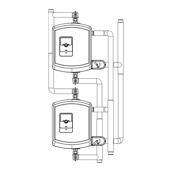
M o n t a g e u n d I n s t a l l a t i o n Drei Bohrpunkte je Station wie zu sehen anzeichnen. Die 6 Bohrlöcher sind ca 70mm tief und mit 10mm zu bohren. Danach werden die Dübel ... - Seite 8 Die Station [15] aufhängen, ausrichten und an den Stockschrauben [4] mithilfe von Kontermuttern befestigen Mithilfe der Blindnietenmutter [9] an der unteren Stockschraube [8] wird die Station senkrecht zur Wand ausgerichtet. Oben und Unten an der Station werden die Übergangsnippel [14] montiert Auf den Übergangsnippeln [14] werden die Eck- Kugelhähne [1] montiert An den WW- Anschluss wird das...
- Seite 9 H y d r a u l i s c h e r A n s c h l u s s m i t Z u b e h ö r Beschreibung: Rx- Cx = Ausgang x vom Regler x. Bsp.: R3- C3 = Ausgang 3 vom Regler 3. Sx- Cx = Sensor x vom regler x.
-
Seite 10: Elektrischer Anschluss
E l e k t r i s c h e r A n s c h l u s s Installation des Stellmotors Der Motor darf nur durch den Hersteller geöffnet werden. Er enthält keine Teile die durch den Nutzer ersetzt oder repariert werden können. - Seite 11 908.19.58.00 Stand 2022/01/31 - 11 -...
- Seite 12 Händler Gebr. Tuxhorn GmbH & Co. KG • Westfalenstr. 36 • 33647 Bielefeld Tel.: +49 (0)521 44808-0 • Fax: +49 (0)521 44808-44 • www.tuxhorn.de...
- Seite 13 ® tubra - nemux-S/M Accessories Cascade pipe system Installation and operating manual...
- Seite 14 Content General information ..................... 3 Intended purpose ....................3 Standards and guidelines ................. 3 Applicable documents ..................3 Scope of delivery ....................4 Delivery and transport ..................4 Technical specifications ..................5 Dimensions/required space ................. 6 Assembly and installation ..................7 Hydraulic connection with accessories ..............
-
Seite 15: General Information
G e n e r a l i n f o r m a t i o n ® This manual describes the installation of the tubra - cascade pipe system for the tubra®- nemux- S/M fresh water module and is only valid in conjunction with the installation and operating manual for the fresh water module tubra®-nemux- S/M. -
Seite 16: Scope Of Delivery
S c o p e o f d e l i v e r y ® ® tubra - cascade pipe system tubra - shut-off set cascade station Item Designation Item Designation 8x 1" flat gasket 2x Angled ball valve 4x washer 5x 1"... -
Seite 17: Technical Specifications
T e c h n i c a l s p e c i f i c a t i o n s tubra®-nemux- S/M Connections Heating side T 1 ¼ (per station) Drinking water side T 1 ¼ Materials Heating side Copper tube Drinking water side... -
Seite 18: Dimensions/Required Space
D i m e n s i o n s / r e q u i r e d s p a c e Designation Description WW / HW Hot water KW / CW Cold water HVL / HF Heating flow HRL / HR Heating return 908.19.58.00... -
Seite 19: Assembly And Installation
A s s e m b l y a n d i n s t a l l a t i o n Score three holes per station as shown. Drill 6 holes to a depth of approx. 70 mm and with a ... - Seite 20 Suspend and align the station [15] and fasten on the hanger bolts [4] using lock nuts Use the blind rivet nuts [9] on the bottom hanger bolt [8] to align the station perpendicular to the wall. Mount the transition nipples [14] at the top and bottom of the station.
- Seite 21 H y d r a u l i c c o n n e c t i o n w i t h a c c e s s o r i e s Description: Rx- Cx = output x from controller x. E.g.: R3- C3 = output 3 from controller 3. Sx- Cx = sensor x from controller x.
-
Seite 22: Electrical Connections
E l e c t r i c a l c o n n e c t i o n s Installing the servo-motor The motor may only be opened by the manufacturer. It does not contain any parts that are replaceable or repairable by the user. - Seite 23 908.19.58.00 Last updated 2022/01/31 - 11 -...
- Seite 24 Reseller Gebr. Tuxhorn GmbH & Co. KG • Westfalenstr. 36 • D- 33647 Bielefeld Tel.: +49 (0)521 44808-0 • Fax: +49 (0)521 44808-44 • www.tuxhorn.de...
- Seite 25 ® tubra - accessori nemux-S/M Tubazioni per cascata Istruzioni di installazione e funzionamento...
- Seite 26 Indice Informazioni generali ................... 3 Scopo di utilizzo ....................3 Istruzioni di sicurezza ..................3 Documenti di riferimento ................... 3 Costruzione ......................4 Consegna e trasporto ..................4 Dati technici ......................5 Dimensioni / ingombri ..................6 Assemblaggio e installazione ................7 Collegamento idraulico con accessori ..............
-
Seite 27: Informazioni Generali
I n f o r m a z i o n i g e n e r a l i Questo manuale descrive l'installazione di tubra®-Tubazioni in cascata sulle stazioni di acqua calda sanitaria dei modulo tubra®-nemux-S/M ed è valido solo in combinazione con le istruzioni di installazione e funzionamento dei relativi moduli. -
Seite 28: Costruzione
C o s t r u z i o n e ® ® tubra -Tubazione per cascata tubra - Modulo di intercettazione per cascata Posizione Denominazione Posizione Denominazione 8x guarnizioni piatte 1 " 2x valvola a sfera angolare 4x rondella 5x guarnizioni piatte 1"... -
Seite 29: Dati Technici
D a t i t e c h n i c i tubra®-tubazioni per cascata per tubra®-nemux-S/M connessioni Lato Riscaldamento G 1 ¼ (per modulo) Lato acqua sanitaria G 1 ¼ Materiale Circuito riscaldamento Rame Circuito acqua sanitaria Acciaio inox Valvola di distribuzione CW617N Servomotore... -
Seite 30: Dimensioni / Ingombri
D i m e n s i o n i / i n g o m b r i Nome Descrizione WW / AC Uscita acqua calda KW / AF Entrata acqua fredda HVL / MANDRISC Mandata riscaldamento HRL / RITRISC Ritorno riscaldamento 908.19.58.00 Ultimo aggiornamento 2022/01/31... -
Seite 31: Assemblaggio E Installazione
A s s e m b l a g g i o e i n s t a l l a z i o n e Marcare i tre punti per la foratura come da figura. Praticare n. 6 fori profondi 70 mm circa e di10mm di diametro. - Seite 32 Agganciare il modulo [15], allinearlo sulle viti [4] e avvitare i dadi avendo cura di avvitare dei controdadi per sicurezza Utilizzando il dado per rivetti ciechi [9] sulla vite inferiore [8] il modulo può essere allineato perpendicolarmente al muro. Installare nei due moduli il nipplo [14] a corredo.
-
Seite 33: Collegamento Idraulico Con Accessori
C o l l e g a m e n t o i d r a u l i c o c o n a c c e s s o r i Descrizione: Rx- Cx = uscita x de controllo x. Bsp.: R3- C3 = uscita 3 de controllo 3. Sx- Cx = sensore x de controllo x. -
Seite 34: Collegamento Elettrico
C o l l e g a m e n t o e l e t t r i c o Installazione del servomotore Il servomotore può essere aperto solo dal produttore. Non contiene parti che possono essere sostituite o riparate dall'utente. Il cavo non deve essere rimosso. - Seite 35 908.19.58.00 Ultimo aggiornamento 2022/01/31 - 11 -...
- Seite 36 Rivenditore Gebr. Tuxhorn GmbH & Co. KG • Westfalenstr. 36 • 33647 Bielefeld Tel.: +49 (0)521 44808-0 • Fax: +49 (0)521 44808-44 • www.tuxhorn.de...
- Seite 37 ® Accessoires tubra - nemux-S/M Tuyauterie de cascade Instructions de montage et de service...
- Seite 38 Contenu Recommandations générales ................3 Utilisation prévue ....................3 Consignes de sécurité ..................3 Documents connexes ..................3 Montage ......................4 Livraison et transport ..................4 Caractéristiques techniques ................5 Dimensions / Encombrement ................6 Montage et installation..................7 Branchement hydraulique avec accessoires ............9 Branchement électrique..................
-
Seite 39: Recommandations Générales
R e c o m m a n d a t i o n s g é n é r a l e s ® Le présent manuel décrit le montage de la tuyauterie de cascade de circulation tubra la station d'eau chaude instantanée tubra®-nemux- S/M et est uniquement valable en liaison avec les instructions de montage et e service de la station d'eau chaude instantanée tubra®-nemux- S. -
Seite 40: Montage
M o n t a g e ® ® Tuyauterie de cascade tubra Kit d'arrêt tubra station de cascade Pos. Désignation Pos. Désignation 8x joint plat 1“ 2x vanne sphérique d'angle 5x joint plat 1“ 4x rondelle 4x vis à double filetage Distributeur M8x180 mm 6x cheville 10 mm... -
Seite 41: Caractéristiques Techniques
C a r a c t é r i s t i q u e s t e c h n i q u e s ® tuyauterie de cascade tubra pour tubra®-nemux- S/M Raccords Côté chauffage F 1 ¼ (chaque station) Côté... -
Seite 42: Dimensions / Encombrement
D i m e n s i o n s / E n c o m b r e m e n t Désignation Description Eau chaude Eau froide Avance de chauffage Retour de chauffage 908.19.58.00 Version 2022/01/31 - 6 -... - Seite 43 M o n t a g e e t i n s t a l l a t i o n Tracer trois points de forage par station comme cela est visible. Les 6 trous doivent être percés avec une profondeur de 70 mm environ et avec ...
- Seite 44 Accrocher la station [15], l'orienter et la fixer sur les vis à double filetage [4] au moyen des contre-écrous La station est orientée verticalement par rapport au mur au moyen des écrous à rivets aveugles [9] sur la vis à double filetage inférieure [8].
- Seite 45 B r a n c h e m e n t h y d r a u l i q u e a v e c a c c e s s o i r e s Description : Rx- Cx = sortie x du régulateur x. Ex. : R3- C3 = sortie 3 du régulateur 3. Sx- Cx = capteur x du régulateur x.
-
Seite 46: Branchement Électrique
B r a n c h e m e n t é l e c t r i q u e Installation du servomoteur Seul le fabricant est habilité à ouvrir le moteur. Il ne contient aucune pièce qui peut être remplacée ou réparée par l'utilisateur. - Seite 47 Remarque : Pour la mise en service, respecter les instructions de montage et de service de la station d'eau chaude instantanée. 908.19.58.00 Version 2022/01/31 - 11 -...
- Seite 48 Revendeur Gebr. Tuxhorn GmbH & Co. KG • Westfalenstr. 36 • D-33647 Bielefeld Tél. : +49 (0)521 44808-0 • Fax : +49 (0)521 44808-44 • www.tuxhorn.de...