MADRIX NEBULA Technisches Handbuch
Vorschau ausblenden
Andere Handbücher für NEBULA:
- Kurzanleitung & technisches handbuch (41 Seiten) ,
- Kurzanleitung & technisches handbuch (37 Seiten) ,
- Technisches handbuch (45 Seiten)
Inhaltsverzeichnis
Verfügbare Sprachen
Verfügbare Sprachen
Inhaltsverzeichnis

Verwandte Anleitungen für MADRIX NEBULA


Inhaltszusammenfassung für MADRIX NEBULA
-
Seite 19: Eingetragene Marken
Erstbenutzung durch. Vergewissern Sie sich, dass Sie alle Informationen verstanden haben. Dieses Handbuch wurde in englischer und deutscher Sprache verfasst. ® (This MADRIX NEBULA Technical Manual is written in English and German.) Entwickelt und hergestellt in Deutschland. Impressum inoage GmbH Internet www.madrix.com... -
Seite 20: Urheberrecht Und Haftungsausschluss
Handhabung, durch Überspannung oder durch anderweitige Ursachen beschädigt wurde. Alle Informationen erhalten Sie im Internet unter www.madrix.com/warranty Lieferumfang 1x MADRIX ® NEBULA 1x Set an steckbaren Schraubklemmen (2x 4-polig und 1x 2-polig) 1x USB 2.0-Kabel (zertifiziert) -
Seite 21: Sicherheitshinweise
Sicherheitshinweise Bitte beachten Sie die nachstehenden Hinweise, um falsche Handhabung, gesundheitliche Schäden oder Geräteschäden zu vermeiden: DAS GERÄT ARBEITET MIT KLEINSPANNUNG (5 V – 24 V GLEICHSTROM). NUTZEN SIE NUR DIESE SPANNUNG! Bei Verwendung von unzulässigen USB-Netzteilen besteht akute Brandgefahr. Max. 5.5 V⎓500 mA am Ausgang erlaubt. Eine externe Spannungsversorgung muss gemäß... -
Seite 22: Benutzung
GW6205, LPD1882S, LPD6803, LPD8806, MBI6024, MBI6120, MY9291, P9883, Neueste Informationen auf SJ1221, SK6112, SK6805, SK6812, SK6813, SK6822, SK9816, SK9822, www.madrix.com) SK9826, SM16703, SM16716, TLC5973, TLS3001, TLS3008, TM1804, TM1809, TM1812, TM1814, TM1829, UCS1903, UCS2903, UCS2904, UCS512B3, UCS8904, UCS9812S, WS2801, WS2803, WS2811, WS2811S, WS2812, WS2812B, WS2813, WS2815, WS2818, WS2822S, WS2822S Addressing Anschlüsse:... -
Seite 23: Kompatibilität
(Siehe S. 14 für das Zurücksetzen des Gerätes, falls benötigt.) Kompatibilität ® MADRIX NEBULA ist ein standardisiertes Gerät für Art-Net und Streaming ACN. Es kann mit sämtlichen kompatiblen Netzwerk-Zuspielern betrieben werden. Siehe Kapitel "Technische Daten" auf S. 4 für weitere Informationen. ®... -
Seite 24: Anschlussmöglichkeiten
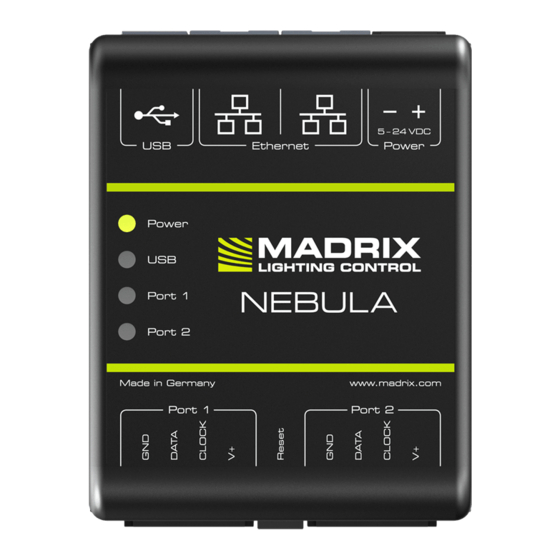
Anschlussmöglichkeiten 1) Spannungsversorgung 2) Netzwerkanschluss rechts, inkl. 2 Status-LEDs 3) Netzwerkanschluss links, inkl. 2 Status-LEDs 4) USB-Anschluss 5) Status-LED für Strom 6) Status-LED für USB 7) Status-LED für Anschluss 1 8) Status-LED für Anschluss 2 9) Anschluss 1 (Port 1) 10) Reset-Taste 11) Hutschienen-Entriegelung 12) Anschluss 2 (Port 2) -
Seite 25: Anschluss Der Leds
Klemme müssen dabei nach oben zeigen. Schritt 4) Datenverbindung wie benötigt über USB oder Netzwerk herstellen. Schritt 5) Die Spannungsversorgung erst herstellen, wenn alle Stromkabel und LEDs an das MADRIX ® NEBULA angeschlossen wurden. Schritt 6) Bitte das richtige Ausgabeprotokoll einstellen, wie in Kapitel "3. - Seite 26 Anschlussvarianten Ihre LEDs, NEBULA und die Datenkabel können auf verschiedene Arten verbunden werden. Auf den folgenden Seiten sind die verschiedenen Varianten als Verbindungsdiagramme dargestellt. Diese sind unabhängig von der Ausrichtung, Platzierung oder Art der Montage. Varianten A1 bis D beziehen sich auf die Datenverbindung über Netzwerk.
- Seite 27 Netzwerk-Daten Beschreibung: Die Spannungsversorgung wird einmal bereitgestellt und an die LEDs (wie benötigt) angeschlossen. Die LEDs sind mit NEBULA über MASSE, DATEN, TAKT bei Bedarf und V+ verbunden. Spannungsversorgung zwischen LEDs und NEBULA aufgrund des erwartbaren Spannungsabfalls über die Länge hinweg. Alternative: Spannungsversorgung am Ende der LED-Kette für LEDs > 9 V.
- Seite 28 über MASSE, DATEN, TAKT bei Bedarf und V+ mit max. 6 A Last je Anschluss. Variante B2 Netzwerk-Daten Spannungsversorg. Beschreibung: Die Spannungsversorgung wird separat für NEBULA und die LEDs (wie benötigt) bereitgestellt. LEDs sind an beiden Anschlüssen verbunden über MASSE, DATEN und TAKT bei Bedarf, aber nicht über V+! Variante C2 Netzwerk-Daten Beschreibung: Die Spannungsvers.
- Seite 29 Variante Y1 – Port 1 od. 2 Daten und Strom über USB Beschreibung: Die Spannungsversorgung wird separat für NEBULA (über USB) und die LEDs (wie benötigt) bereitgestellt. Die LEDs sind mit NEBULA verbunden über MASSE, DATEN und TAKT bei Bedarf, aber nicht über V+!
- Seite 30 Variante Y2 Daten und Strom über USB Beschreibung: Die Spannungsversorgung wird separat für NEBULA (über USB) und die LEDs (wie benötigt) bereitgestellt. LEDs sind an beiden Anschlüssen verbunden über MASSE, DATEN und TAKT bei Bedarf, aber nicht über V+! Variante Z Daten über USB...
-
Seite 31: Gerätekonfiguration
3. Geräte-Konfiguration Schritt 1) Verbinden Sie NEBULA und den PC mit demselben Netzwerk. Schritt 2) Stellen Sie die richtigen Netzwerkeinstellungen im Betriebssystem ein. (Empfohlen: IP-Adresse 10.0.0.1 / Subnetzmaske 255.0.0.0) Schritt 3) Öffnen Sie einen Webbrowser und geben Sie die IP-Adresse des NEBULA ein. -
Seite 32: Anzeige Der Status-Leds
Anzeige der Status-LEDs -LED P TATUS TATUS OWER PANNUNGSVERSORGUNG Ausgeschaltet Keine Spannungsversorgung. � Das Gerät hat keinen Strom. Spannungsversorgung liegt an. � Das Gerät hat Strom. Permanent grün Grün blinkend Bootloader aktiviert. � Zurücksetzen / Firmware einspielen. -LED USB TATUS TATUS Ausgeschaltet USB nicht angeschlossen. -
Seite 33: Montage Auf Hutschienen
– "Systemeinstellungen" > "Optionen..." > "USB-Geräte" für USB, – "Systemeinstellungen" > "Optionen..." > "Netzwerkgeräte" für sACN, – "Systemeinstellungen" > "Geräteverwaltung..." > "Art-Net" für Art-Net. Danach können die Geräte konfiguriert und aktiviert werden: – "Systemeinstellungen" > "Geräteverwaltung..." > "DMX-Geräte". Weitere Informationen finden Sie im Benutzerhandbuch von MADRIX ®... -
Seite 34: Aktualisieren Der Firmware
– Konsultieren Sie das allgemeine Benutzerhandbuch ("User Manual"), – Kontaktieren Sie Ihren Händler, – Besuchen Sie die Webseite und das Forum unter www.madrix.com, – Anfragen können auch direkt per Telefon oder per E-Mail erfolgen. Altgeräte und Entsorgung Das Gerät, sein Zubehör sowie Verpackungsmaterial müssen ordnungsgemäß... -
Seite 35: Häufig Gestellte Fragen
Wo finde ich die neueste Firmware für mein Gerät? ® Nutzen Sie die Software MADRIX HARDWARE MANAGER (siehe S. 16). ® Kann ich andere Zuspieler an Stelle von MADRIX 5 benutzen? Ja. Wenn Sie das Gerät als reines Netzwerkgerät nutzen. Brauche ich zusätzlich eine MADRIX ®... - Seite 36 www.madrix.com...