Würth DIGITAL-MULTIMETER-TD6 Bedienungsanleitung

Verwandte Anleitungen für Würth DIGITAL-MULTIMETER-TD6


Inhaltszusammenfassung für Würth DIGITAL-MULTIMETER-TD6
- Seite 1 MULTIMETRO DIGITALE DIGITALES MULTIMETER DIGITAL MULTIMETER Art. 0715 53 429 Istruzioni d'uso Bedienungsanleitung Operating instructions...
- Seite 2 ......5 – 21 ......23 – 39 ......41 – 58...
- Seite 20 ......5 – 21 ......23 – 39 ......41 – 58...
- Seite 21 INHALT Sicherheitshinweise ............24 1.1. Vorbereitung ................24 1.2. Während des Gebrauchs ............25 1.3. Nach dem Gebrauch ............25 1.4. Überspannungskategorien-Definitionen ........ 25 Allgemeine Beschreibung ..........26 Vorbereitungen für den Gebrauch ......26 3.1. Vorabprüfung ................. 26 3.2. Stromversorgung ..............26 3.3. Lagerung ................. 26 Elemente des Geräts ............27 4.1. Messgerätebeschreibung ............
-
Seite 22: Sicherheitshinweise
1 Sicherheitshinweise Dieses Multimeter entspricht dem • Nehmen Sie keine Messungen vor, wenn Sie Sicherheitsstandard IEC/EN61010-1 anomale Bedingungen wie Bruchschäden, für elektronische Messgeräte. Zu ihrer Deformationen, Sprünge, Austritt von Batte- eigenen Sicherheit und um Schäden rieflüssigkeit, keine Anzeige am Display etc. des Gerätes zu vermeiden, folgen bemerken sie bitte den Hinweisen in dieser... -
Seite 23: Während Des Gebrauchs
1.2. Während des Gebrauchs Lesen Sie die Empfehlungen, folgen Sie den Anweisungen in diesem Handbuch: ACHTUNG Nichteinhaltung der Warnungen und/oder den Anwendungsvorschriften kann das Gerät und/oder seine Bauteile beschädigen, oder den Benutzer verletzen. • Wenn Sie den zu messenden Bereich änd- bitte keine Spannung hinzu. Obwohl es ern, trennen Sie die Messleitungen zuerst eine Schutzschaltung gibt, verursacht überm- vom zu prüfenden Objekt, um jede Gefahr äßige Spannung immer noch eine Funktions- zu vermeiden... -
Seite 24: Allgemeine Beschreibung
2. Allgemeine Beschreibung • Das Multimeter kann folgende Messun- Jede dieser Funktionen kann mittels des Dreh- gen (alle mit automatischer Bereichswahl) schalters gewählt werden. Ebenso stehen die ausführen: Funktion-Tasten (siehe Kapitel 4.2) um den angezeigten Wert festzuhalten. Die Auswahl wird • Gleichspannung DC durch Anzeige der Einheiten und aktiven Funktio- •... -
Seite 25: Elemente Des Geräts
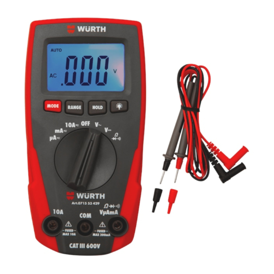
4. Elemente des Geräts 4.1. Messgerätbeschreibung °C°F HOLD AUTO LEGENDE: HOLD 1. LCD-Anzeige AUTO 2. MODE Taste 3. Taste 4. RANGE Taste 5. HOLD Taste 6. Funktionswahlschalter 7. 10A Eingangsbuchse 8. VmAμA Eingangsbuchse 9. COM Eingangsbuchse MAX 200mA MAX 200mA Abb. 1: Messgerätebeschreibung... -
Seite 26: Funktionstasten
4.2. Funktionstasten Dezimalpunkt auf dem Display zu fixieren. Um die 4.2.1. HOLD Taste Funktion zu beenden, halten Sie die RANGE-Taste für mindestens 1 Sekunde gedrückt oder drehen Durch Drücken der HOLD-Taste wird der ange- Sie den Drehschalter in eine andere Position. Diese zeigte Wert festgehalten und das - Sym- HOLD Funktion ist nicht aktiv bei Position ... -
Seite 27: Anweisungen Zum Gebrauch
5. Anweisungen zum Gebrauch 5.1. Gleichspannungsmessung-DC ACHTUNG AUTO Die max. Eingangsgleichspan- nung ist 600V. Versuchen Sie keine Spannung zu messen, die höher ist. Es besteht die Gefahr eines Stromschlages und das Multimeter könnte zerstört werden. MAX 200mA Abb. 2: Gleichspannungsmessung-DC 1. Stellen Sie den Drehschalter in die Position V . Das “DC” Symbol wird angezeigt 2. Verbinden Sie die Messleitungen wie folgt: die rote Messleitung in die Buchse VmAμA und die schwarze Messleitung in die COM Buchse 3. -
Seite 28: Wechselpannungsmessung-Ac
5.2. Wechselspannungsmessung-AC ACHTUNG AUTO Die max. Eingangswechsel- spannung ist 600V. Versu- chen Sie keine Spannung zu messen, die höher ist. Es besteht die Gefahr eines Stromschlages und das Multi- meter könnte zerstört werden. MAX 200mA Abb. 3: Wechselspannungsmessung-AC 1. Stellen Sie den Drehschalter in die Position V 2. Verbinden Sie die Messleitungen wie folgt: die rote Messleitung in die Buchse VmAμA und die schwarze Messleitung in die COM Buchse 3. -
Seite 29: Widerstandsmessung
5.3. Widerstandsmessung ACHTUNG AUTO Stellen Sie vor dem Dioden- und Widerstandstest sicher, dass sich keine Spannung mehr im Messkreis befindet und entladen Sie alle Kon- densatoren. MAX 200mA Abb. 4: Widerstandsmessung 1. Stellen Sie den Drehschalter in die Position . Das „M “ Symbol wird angezeigt 2. Verbinden Sie die Messleitungen wie folgt: die rote Messleitung in die Buchse VmAμA und die schwarze Messleitung in die COM Buchse 3. -
Seite 30: Diodentest & Durchgangsprüfung
5.4. Diodentest & Durchgangsprüfung ACHTUNG Stellen Sie vor dem Dioden- und Widerstandstest sicher, dass sich keine Span- nung mehr im Messkreis befindet und entladen Sie alle Kondensatoren. MAX 200mA MAX 200mA Abb. 5: Diodentest und Durchgangsprüfung 1. Stellen Sie den Drehschalter in die Position 2. Drücken Sie nun die MODE Taste bis das Symbol „ “ angezeigt wird 3. Verbinden Sie die Messleitungen wie folgt: die rote Messleitung in die Buchse VmAμA und die schwarze Messleitung in die COM Buchse 4. -
Seite 31: Gleichstrommessung-Dc
5.5. Gleichstrommessung-DC ACHTUNG Der maximale DC Eingangsgleichstrom ist 10A (10A Eingang) oder 200mA (beim VmAμA Eingang). Versu- chen Sie nicht, Ströme zu messen, die die Grenzwerte, die in diesem Hand- AUTO buch angegebenen werden, übersteigen. Das Überschreiten der Stromgrenzwerte könnte einen elektrischen Schock verur- sachen und das Messgerät beschädigen. MAX 200mA Abb. 6: Verwendung des Gerätes für Gleichstrommessung-DC 1. Trennen Sie die Versorgung des zu messenden Kreises. 2. Wählen Sie Stellungen “µA ”, “mA ” oder “10A ” aus. 3. -
Seite 32: Wechselstrommessung-Ac
5.6. Wechselstrommessung-AC ACHTUNG Der maximale Eingangswechselstrom ist 10A (10A Eingang) oder 200mA (beim VmAμA Eingang). Ver- suchen Sie nicht, Ströme zu messen, die die Grenzwerte, die in diesem AUTO Handbuch angegebenen werden, übersteigen. Das Überschreiten der Stromgrenzwerte könnte einen elekt- rischen Schock verursachen und das Messgerät beschädigen. MAX 200mA Abb. 7: Verwendung des Gerätes für Wechselstrom- messung-AC 1. Trennen Sie die Versorgung des zu messenden Kreises. 2. Wählen Sie Stellungen “µA ”, “mA ” oder “10A ” aus. 3. -
Seite 33: Allgemeines
6. Wartung 6.1. Allgemeines Schmelzsicherungen-Wechsel Wir bitten Sie, ob im Gebrauch oder in der Lage- 1. Drehen Sie den Funktionswahlschalter in die rung, die Spezifizierungsvoraussetzungen nicht zu OFF-Stellung und ziehen Sie die Anschlusskabel überschreiten, um damit auch irgendwelchen mög- aus den Eingangsbuchsen. lichen Schäden oder Gefahren während des Ge- 2. -
Seite 34: Technische Daten
7. Technische Daten 7.1. Technische Funktionen Messgenauigkeit angegeben als ±[%Abl + (Anz. Ziff*Auflösung)] bei 23°C±5°C, <80%RH. Gleichspannung DC Überspannungs- Auflösung Genauigkeit Eingangswiderstand Bereich schutz 0.1mV ± (0.8%Abl + 2Ziff) 200.0mV 0.001V 2.000V 0.01V 600VDC/ACrms ± Ω 20.00V (1.5%Abl + 2Ziff) 0.1V 200.0V ± 600V (2.0%Abl + 2Ziff) Wechselspannung AC (Autorange) Genauigkeit (*) Überspannungs- Auflösung Eingangswiderstand... - Seite 35 7. Technische Daten Wechselstrom AC Genauigkeit (*) Auflösung Überspannungsschutz Bereich (50Hz ∻ 400Hz) 0.1µA 200.0µA 1µA 2000µA ±(2.0%Abl + 5Ziff) Schnellschmelzsicherung 200mA/600V 0.01mA 20.00mA 0.1mA 200.0mA 0.001A 2.000A Schnellschmelzsicherung 10A/600V ±(3.0%Abl + 7Ziff) 10.00A 0.01A (*) Genauigkeit spezifiziert von sinusförmige Wellenform Widerstand und Durchgangstest Überspannungs- Auflösung Genauigkeit Signalton bei Bereich schutz...
-
Seite 36: Bezugsnormen
7.1.1. Bezugsnormen Sicherheit: IEC/EN 61010-1 EMC: IEC/EN61326-1 Isolierung: Doppelte Isolation Verschmutzungsgrad: Überspannungskategorie: CAT III 600V 7.1.2. Allgemeine Daten Mechanische Eigenschaften Abmessungen (L x B x H): 145 x 70 x 60mm Gewicht (inklusive Batterien): 245g Schutzklasse: IP40 Stromversorgung Batterietyp: 2x1.5V Batterie Typ AAA IEC LR03 Anzeige schwacher Batterien: Symbol " "... -
Seite 37: Zubehör
8. Service 8.1. Garantiebestimmungen • Reparaturen, die aufgrund unsachgemäßer Ver- wendung (einschließlich Anpassung an bestimmte Für dieses Gerät gewähren wir Garantie auf Mate- Anwendungen, die in der Bedienungsanleitung rial- oder Produktionsfehler, entsprechend unseren nicht berücksichtigt sind) oder durch unsachgemä- allgemeinen Geschäftsbedingungen. Während der ße Kombination mit inkompatiblen Zubehörteilen Garantiefrist behält sich Würth das Recht vor, das oder Geräten erforderlich werden... - Seite 38 ......5 – 21 ......23 – 39 ......41 – 58...