Vaillant sensoCOMFORT VRC 720/2 Betriebs Und Installationsanleitung
Vorschau ausblenden
Andere Handbücher für sensoCOMFORT VRC 720/2:
- Betriebs und installationsanleitung (56 Seiten)
Inhaltsverzeichnis
Fehlerbehebung

Verwandte Anleitungen für Vaillant sensoCOMFORT VRC 720/2


Inhaltszusammenfassung für Vaillant sensoCOMFORT VRC 720/2
- Seite 1 sensoCOMFORT VRC 720/2 de Betriebs- und Installationsanleitung fr Notice d’utilisation et d’installation it Istruzioni per l'uso e l'installazione nl Gebruiksaanwijzing en installatiehandleiding en Country specifics...
- Seite 2 Betriebs- und Installationsanleitung ....3 Notice d’utilisation et d’installation ....54 Istruzioni per l'uso e l'installazione ....107 Gebruiksaanwijzing en installatiehandleiding ........160 Country specifics..........211...
-
Seite 3: Inhaltsverzeichnis
Betriebs- und Installationsanleitung CE-Kennzeichnung..........48 Garantie und Kundendienst ......... 48 Inhalt Recycling und Entsorgung........48 Produktdaten gemäß der EU Verordnung Nr. 811/2013, 812/2013..........49 Sicherheit ............. 4 Technische Daten - Systemregler ....... 49 Bestimmungsgemäße Verwendung ...... 4 Anhang ................50 Allgemeine Sicherheitshinweise ...... -
Seite 4: Sicherheit
auch jede unmittelbare kommerzielle und Sicherheit industrielle Verwendung. Bestimmungsgemäße Verwendung Achtung! Bei unsachgemäßer oder nicht bestimmungs- Jede missbräuchliche Verwendung ist unter- gemäßer Verwendung können Beeinträchti- sagt. gungen des Produkts und anderer Sachwerte entstehen. Allgemeine Sicherheitshinweise Das Produkt ist dafür vorgesehen, eine 1.2.1 Qualifikation Heizungsanlage mit Wärmeerzeugern des Folgende Arbeiten dürfen nur Fachhand-... -
Seite 5: Gültigkeit: Italien
Gültigkeit: Italien Sie finden eine Liste relevanter Normen unter: https://www.vaillant.it/professionisti/normative /riferimenti-normativi-prodotto/ 0020287842_02 Betriebs- und Installationsanleitung... -
Seite 6: Produktbeschreibung
Produktbeschreibung Was bedeutet Zeitfenster? Beispiel Heizbetrieb im Modus: Zeitgesteuert Welche Nomenklatur wird verwendet? – Systemregler: statt VRC 720 – Fernbedienung: statt VR 92 – Funktionsmodul FM3 oder FM3: statt VR 70 24 °C – Funktionsmodul FM5 oder FM5: statt VR 71 21 °C Was bewirkt die Frostschutzfunktion? Die Frostschutzfunktion schützt die Heizungsanlage und die... -
Seite 7: Heizkurve Einstellen
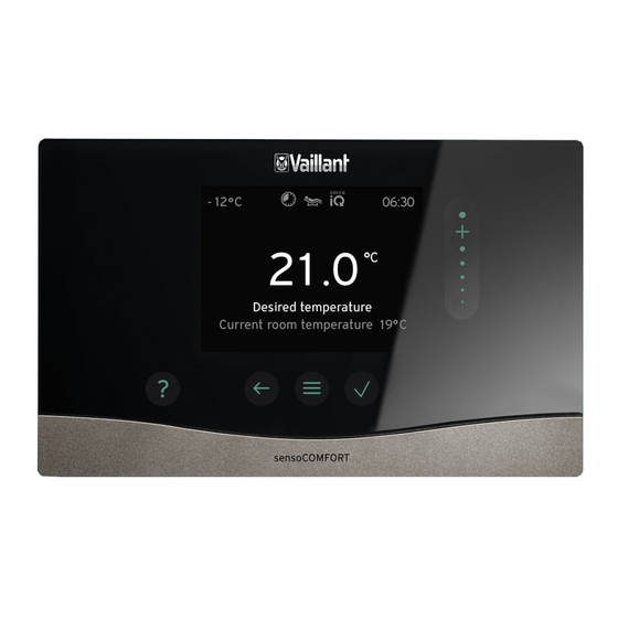
2.10 Heizkurve einstellen 2.11 Display, Bedienelemente und Symbole Außentemperatur °C Vorlaufsolltemperatur 2.11.1 Bedienelemente °C – Menü aufrufen Die Abbildung zeigt die möglichen Heizkurven von 0,1 bis – Zurück zum Hauptmenü 4.0 für eine Raumsolltemperatur 20 °C. Wenn z. B. die Heiz- kurve 0.4 ausgewählt ist, dann wird bei einer Außentempe- –... -
Seite 8: Bedien- Und Anzeigefunktionen
2.12 Bedien- und Anzeigefunktionen Hinweis Die in diesem Kapitel beschriebenen Funktionen stehen nicht für alle Systemkonfigurationen zur Verfügung. Um das Menü aufzurufen, drücken Sie 2 x 2.12.1 Menüpunkt REGELUNG MENÜ → REGELUNG → Zone → Heizen → Modus: → Manuell →... - Seite 9 MENÜ → REGELUNG → Modus: → Manuell → Warmwassertemperatur: °C Ununterbrochenes Halten der Warmwassertemperatur → Zeitgesteuert → Wochenplaner Warmwasser → Warmwassertemperatur: °C → Wochenplaner Zirkulation Wochenplaner Warmwasser: bis zu 3 Zeitfenster sind pro Tag einstellbar Warmwassertemperatur: °C: gilt innerhalb der Zeitfenster Außerhalb der Zeitfenster ist der Warmwasserbetrieb ausgeschaltet Wochenplaner Zirkulation: bis zu 3 Zeitfenster sind pro Tag einstellbar Innerhalb der Zeitfenster pumpt die Zirkulationspumpe warmes Wasser zu den Zapfstellen...
-
Seite 10: Menüpunkt Information
2.12.2 Menüpunkt INFORMATION MENÜ → INFORMATION → Aktuelle Temperaturen → Zone → Warmwassertemperatur → Warmwasser Kreis 1 → Wasserdruck: bar → Aktuelle Raumluftfeuchte → Energiedaten → Solarertrag → Umweltertrag → Stromverbrauch → Heizen → Warmwasser → Kühlen → Anlage → Brennstoffverbrauch →... - Seite 11 MENÜ → REGELUNG → Estrichtrocknung Die Funktion Estrichtrocknungsprofil für frisch verlegten Estrich entsprechend der Bauvorschriften aktivieren. Der Systemregler regelt die Vorlauftemperatur unabhängig von der Außentemperatur. Estrichtrock- nung einstellen Menüpunkt Anlagenkonfiguration (→ Kapitel 2.12.4) → Code ändern → Sprache, Uhrzeit, Display →...
- Seite 12 MENÜ → EINSTELLUNGEN → Fachhandwerkerebene → Anlagenkonfiguration → Kühlen bei Außentemperatur: °C Kühlen startet, wenn die Außentemperatur (24 Stunden gemittelt) die eingestellte Tempera- tur überschreitet. Werkseinstellung: 15 °C → Quellenregenerierung: Der Systemregler schaltet die Funktion Kühlen ein und leitet die Wärme aus dem Wohn- raum über die Wärmepumpe in die Erde zurück.
- Seite 13 MENÜ → EINSTELLUNGEN → Fachhandwerkerebene → Anlagenkonfiguration → Zusatzheizgerät: → WW + Heizen Das Zusatzheizgerät unterstützt die Wärmepumpe nicht. Werkseinstellung: WW + Heizen Für den Legionellenschutz, Frostschutz oder die Enteisung wird das Zu- satzheizgerät aktiviert. → Heizen Das Zusatzheizgerät unterstützt die Wärmepumpe beim Heizen. Für den Legionellenschutz wird das Zusatzheizgerät aktiviert.
- Seite 14 MENÜ → EINSTELLUNGEN → Fachhandwerkerebene → Anlagenkonfiguration → Konfiguration WP-Regelungsmodul → MA 2: Funktionbelegung des Multifunktionsausgangs auswählen. Werkseinstellung: Zirkulations- pumpe → ME: → Nicht verbun- Der Systemregler ignoriert das anstehende Signal. Werkseinstellung: 1 x Zirkulation → 1 x Zirkula- Der Betreiber hat die Taste für die Zirkulation gedrückt. Der Systemreg- tion ler aktiviert die Zirkulationspumpe für einen kurzen Zeitraum.
- Seite 15 MENÜ → EINSTELLUNGEN → Fachhandwerkerebene → Anlagenkonfiguration → Max. Vorlaufsolltemperatur: °C Obergrenze für die Vorlaufsolltemperatur eingeben. Der Systemregler vergleicht den einge- stellten Wert mit der berechneten Vorlaufsolltemperatur und regelt auf den kleineren Wert. Werkseinstellung: – 90 °C bei konventionellem Wärmeerzeuger –...
- Seite 16 MENÜ → EINSTELLUNGEN → Fachhandwerkerebene → Anlagenkonfiguration → Status Pumpe: → Status Mischventil: % → Zone → Zone aktiviert: Deaktivieren nicht benötigter Zonen. Alle vorhandenen Zonen erscheinen im Display. Vor- aussetzung: Die vorhandenen Heizkreise sind in der Funktion Kreisart: aktiviert. Werkseinstellung: Ja →...
- Seite 17 MENÜ → EINSTELLUNGEN → Fachhandwerkerebene → Anlagenkonfiguration → Max. Vorlaufsolltemp. WW: °C Einstellen der maximalen Vorlaufsolltemperatur des Pufferspeichers für die Trinkwasser- station. Die eingestellte maximale Vorlaufsolltemperatur muss kleiner sein als die maximale Vorlauftemperatur des Wärmeerzeugers. Bei zu klein eingestellter maximaler Vorlaufsolltemperatur kann die Trinkwasserstation die Solltemperatur nicht erreichen.
- Seite 18 MENÜ → EINSTELLUNGEN → Fachhandwerkerebene → Anlagenkonfiguration → 2. TD-Regelung → Einschaltdifferenz: K Einstellen des Differenzwerts für den Start der Temperaturdifferenzergeleung, wie z. B. einer solaren Heizungsunterstützung. Ist die Temperaturdifferenz zwischen TD-Sensor 1 und TD-Sensor 2 größer als die einge- stellte Einschaltdifferenz und die eingestellte Minimaltemperatur am TD-Sensor 1, wird die Temperaturdifferenzregelung gestartet.
-
Seite 19: Elektroinstallation, Montage
-- Elektroinstallation, Montage Die Elektroinstallation darf nur von einer Elektrofachkraft durchgeführt werden. Die Heizungsanlage muss außer Betrieb genommen werden, bevor Arbeiten daran durchgeführt werden. Auswahl der Leitungen ▶ Verwenden Sie für Netzspannungsleitungen keine fle- xiblen Leitungen. ▶ Verwenden Sie für Netzspannungsleitungen Mantel-Lei- tungen. -
Seite 20: Systemregler Und Außentemperatursensor Montieren
Systemregler und Außentemperatursensor montieren Ø6 VRC 720 VRC 693 VRC 9535 H05VVF 2 x 0,75 mm² VRC 720 Ø 6 Betriebs- und Installationsanleitung 0020287842_02... - Seite 21 VRC 693, VRC 9535 ≥ 2 VRC 693 Ø 6 0020287842_02 Betriebs- und Installationsanleitung...
- Seite 22 VRC 9535 Ø 6 Betriebs- und Installationsanleitung 0020287842_02...
-
Seite 23: Einsatz Der Funktionsmodule, Systemschema, Inbetriebnahme
-- Einsatz der Funktionsmodule, Systemschema, Inbetriebnahme System ohne Funktionsmodule VRC 720 eBUS Einfache Systeme mit einem direkten Heizkreis benötigen kein Funktionsmodul. System mit Funktionsmodul FM3 FM3 (VR 70) VRC 720 eBUS Systeme mit zwei Heizkreisen, die getrennt voneinander geregelt werden müssen, benötigen das Funktionsmodul FM3. Das System ist nicht mit der Fernbedienung VR 92 erweiterbar. -
Seite 24: System Mit Funktionsmodulen Fm5 Und Fm3
System mit Funktionsmodulen FM5 und FM3 FM5 (VR 71) FM3 (VR 70) VRC 720 VR 92 eBUS Systeme mit mehr als 2 gemischten Heizkreisen benötigen das Funktionsmodul FM5. Das System kann umfassen: – maximal 1 Funktionsmodul FM5 – maximal 3 Funktionsmodulen FM3, zusätzlich zum Funktionsmodul FM5 –... -
Seite 25: Funktionsmodule Fm3 Und Fm5
4.4.3 Funktionsmodule FM3 und FM5 Wenn in einem System die Funktionsmodule FM3 und FM5 installiert sind, dann erweitert jedes zusätzlich installierte Funkti- onsmodul FM3 das System um zwei gemischte Heizkreise. Die mögliche Konfiguration (FM3+FM5) entspricht einer definierten Anschlussbelegung des Funktionsmoduls FM3 (→... -
Seite 26: Sensorbelegung
Konfigu- ration – – SysFlow BufBt BufBtCH BufTop BufBt DEM1 DEM2 DEM3 Bedeutung der Abkürzungen (→ Kapitel 4.9.1) Sensorbelegung Konfigura- tion – – – VR 10 VR 10 VR 10 VR 10 VR 10 VR 10 VR 11 VR 10 VR 10 VR 10 –... -
Seite 27: Einstellungen Des Systemschema-Codes
Sensorbelegung Konfiguration – – – – – FM3+FM5 VR 10 VR 10 – – – – VR 10 VR 10 VR 10 Einstellungen des Systemschema-Codes Die Systeme sind grob nach angeschlossenen Systemkomponenten gruppiert. Jede Gruppierung erhält einen System- schema-Code, den Sie in den Systemregler in der Funktion Systemschema-Code: eintragen müssen. Der Systemregler benötigt den Systemschema-Code, um die systembedingten Funktionen freizuschalten. -
Seite 28: Wärmepumpe Als Einzelgerät (Hybrid)
4.7.4 Wärmepumpe als Einzelgerät (hybrid) Mit externem Zusatzheizgerät Ein Zusatzheizgerät (mit eBUS) wird über VR 32 angeschlossen (Adresse 2). Ein Zusatzheizgerät (ohne eBUS) wird am Ausgang der Wärmepumpe bzw. des Wärmepumpenregelungsmoduls für das externe Zusatzheizgerät angeschlossen. Systemeigenschaft Systemschema-Code: ohne mit Wärme- Wärme- tauscher tauscher... - Seite 29 System- System ohne mit FM5 schema- FM5, Konfiguration Code: ohne max. 3 solare Warm- solare Heizungs- wasserbereitung unterstützung für konventionelle Wärmeerzeuger – – Gas-/Ölheizgerät – – – – – – – Gas-/Ölheizgerät, Kaskade – – – – Gas-/Ölheizgerät – – –...
-
Seite 30: Systemschema Und Verbindungsschaltplan
Systemschema und Verbindungsschaltplan Abkürzung Bedeutung 4.9.1 Bedeutung der Abkürzungen Kappenventil 9k[x] 3-Wege-Mischer Abkürzung Bedeutung 3-Wege-Mischer Kühlen Wärmeerzeuger Thermostatmischer Zusatzheizgerät Warmwasser Durchflussmesser (Taco-Setter) Zusatzheizgerät Heizung Kaskadenventil Zusatzheizgerät Warmwasser/Heizung Thermometer Luft-Wasser-Wärmepumpe Manometer Außeneinheit Split-Wärmepumpe Rückschlagventil Inneneinheit Split-Wärmepumpe Luftabscheider Umwälzpumpe Wärmeerzeuger Schmutzfänger mit Magnetitabscheider Umwälzpumpe Schwimmbad Solar-/Soleauffangbehälter Speicherladepumpe... - Seite 31 Abkürzung Bedeutung Schnittstelle zum Photovoltaik-Wechselrich- PWM Signal für Pumpe Raumthermostat Signal Kühlung Schnittstelle zum Übertragungsnetzbetreiber Solar yield Solarertragssensor SysFlow Systemtemperatursensor TD1, TD2 Temperatursensor für eine Temperaturdiffe- renzregelung Schalteingang zur Fernsteuerung Trennschaltung mit schaltendem Heizkessel 0020287842_02 Betriebs- und Installationsanleitung...
- Seite 32 4.9.2 Systemschema 0020184677 4.9.2.1 Einstellung am Systemregler Systemschema-Code: 1 Betriebs- und Installationsanleitung 0020287842_02...
- Seite 33 4.9.2.2 Systemschema 0020184677 0020287842_02 Betriebs- und Installationsanleitung...
- Seite 34 4.9.2.3 Verbindungsschaltplan 0020184677 Betriebs- und Installationsanleitung 0020287842_02...
- Seite 35 4.9.3 Systemschema 0020178440 4.9.3.1 Einstellung am Systemregler Systemschema-Code: 1 Konfiguration FM3: 1 MA FM3: Zirkulationspumpe Kreis 1 / Kreisart: Heizen Kreis 2 / Kreisart: Heizen Zone 1/Zone aktiviert: Ja Zone 2/Zone aktiviert: Ja 0020287842_02 Betriebs- und Installationsanleitung...
- Seite 36 4.9.3.2 Systemschema 0020178440 Betriebs- und Installationsanleitung 0020287842_02...
- Seite 37 4.9.3.3 Verbindungsschaltplan 0020178440 Burn. 24V= 0020287842_02 Betriebs- und Installationsanleitung...
-
Seite 38: Besonderheiten Des Systems
4.9.4 Systemschema 0020177912 4.9.4.1 Besonderheiten des Systems 8: Durch einen Referenzraum ohne Einzelraum-Temperaturregulierventil muss immer min. 35 % der Nenndurchfluss- menge fließen können. 4.9.4.2 Einstellungen am Systemregler Systemschema-Code: 8 Kreis 1 / Raumaufschaltung: Aktiv oder Erweitert Zone 1 / Zonenzuordnung: Regler 4.9.4.3 Einstellungen in der Wärmepumpe Kühlungstechnologie: Keine Kühlung Betriebs- und Installationsanleitung 0020287842_02... - Seite 39 4.9.4.4 Systemschema 0020177912 0020287842_02 Betriebs- und Installationsanleitung...
- Seite 40 4.9.4.5 Verbindungsschaltplan 0020177912 Betriebs- und Installationsanleitung 0020287842_02...
- Seite 41 4.9.5 Systemschema 0020280010 4.9.5.1 Besonderheiten des Systems 5: Der Speichertemperaturbegrenzer muss an einer geeigneten Stelle montiert werden, um eine Speichertemperatur über 100 °C zu vermeiden. 4.9.5.2 Einstellungen am Systemregler Systemschema-Code: 1 Konfiguration FM5: 2 MA FM5: Legio.schutzpump. Kreis 1 / Kreisart: Heizen Kreis 1 / Raumaufschaltung: Aktiv oder Erweitert Kreis 2 / Kreisart: Heizen Kreis 2 / Raumaufschaltung: Aktiv oder Erweitert...
- Seite 42 4.9.5.4 Systemschema 0020280010 Betriebs- und Installationsanleitung 0020287842_02...
- Seite 43 4.9.5.5 Verbindungsschaltplan 0020280010 0020287842_02 Betriebs- und Installationsanleitung...
- Seite 44 4.9.6 Systemschema 0020260774 4.9.6.1 Besonderheiten des Systems 17: Optionale Komponente 4.9.6.2 Einstellung am Systemregler Systemschema-Code: 1 Konfiguration FM5: 6 Kreis 1 / Kreisart: Heizen Kreis 1 / Raumaufschaltung: Aktiv oder Erweitert Kreis 2 / Kreisart: Heizen Kreis 2 / Raumaufschaltung: Aktiv oder Erweitert Kreis 3 / Kreisart: Heizen Kreis 3 / Raumaufschaltung: Aktiv oder Erweitert Zone 1/Zone aktiviert: Ja...
- Seite 45 4.9.6.4 Systemschema 0020260774 0020287842_02 Betriebs- und Installationsanleitung...
- Seite 46 4.9.6.5 Verbindungsschaltplan 0020260774 Betriebs- und Installationsanleitung 0020287842_02...
-
Seite 47: Inbetriebnahme
2.3. Schalten Sie die Wärmepumpe (bei Kaskaden -- Inbetriebnahme Wärmpumpe 1) und ggf. FM5 wieder ein. ◁ Der Systemregler erhält die Information, dass Voraussetzungen zur Inbetriebnahme der Kühlbetrieb der Wärmepumpe aktiviert ist. – Die Montage und Elektroinstallation von Systemregler Navigieren Sie im Systemregler zur Funktion MENÜ | und Außentemperatursensor ist abgeschlossen. -
Seite 48: Fehlermeldung
Fehlermeldung CE-Kennzeichnung Im Display erscheint mit dem Text der Fehlermeldung. Fehlermeldungen finden Sie unter: MENÜ → EINSTELLUN- GEN → Fachhandwerkerebene → Fehlerhistorie Mit der CE-Kennzeichnung wird dokumentiert, dass die Pro- dukte gemäß der Konformitätserklärung die grundlegenden Fehlerbehebung (→ Anhang B.2) Anforderungen der einschlägigen Richtlinien erfüllen. -
Seite 49: Produktdaten Gemäß Der Eu Verordnung Nr
Produktdaten gemäß der EU Verordnung Nr. 811/2013, 812/2013 Die jahreszeitbedingte Raumheizungs-Effizienz beinhaltet bei Geräten mit integrierten, witterungsgeführten Reglern inklusive aktivierbarer Raumthermostatfunktion immer den Korrekturfaktor der Reglertechnologieklasse VI. Eine Abwei- chung der jahreszeitbedingten Raumheizungs-Effizienz ist bei Deaktivierung dieser Funktion möglich. Klasse des Temperaturreglers Beitrag zur jahreszeitbedingten Raumhei- 4,0 % zungs-Energieeffizienz ηs... -
Seite 50: Anhang
Anhang Störungsbehebung, Wartungsmeldung Störungsbehebung Störung mögliche Ursache Maßnahme Display bleibt dunkel Softwarefehler Drücken Sie die Taste oben rechts auf dem Systemregler länger als 5 Sekunden, um einen Neustart zu erzwingen. Schalten Sie den Netzschalter an allen Wärmeerzeugern für ca. 1 Minute aus und dann wieder ein. Wenn die Fehlermeldung bestehen bleibt, dann benachrich- tigen Sie den Fachhandwerker. -
Seite 51: B.2 Fehlerbehebung
Störung mögliche Ursache Maßnahme Wärmeerzeuger heizt bei er- falscher Wert in der Funktion StellenSie in der Funktion Raumaufschaltung: den Wert reichter Raumtemperatur weiter Raumaufschaltung: oder Zo- Aktiv oder Erweitert ein. nenzuordnung: Ordnen Sie in der Zone, in der der Systemregler installiert ist, in der Funktion Zonenzuordnung: die Adresse des Sys- temreglers zu. -
Seite 52: B.3 Wartungsmeldungen
Code/Bedeutung mögliche Ursache Maßnahme ▶ Schichtladespeicher nicht unter- Unpassender Speicher ange- Entfernen Sie den Speicher aus der Heizungsanlage. stützt schlossen Konfiguration MA2 WP-Re- Fehlerhaft angeschlossenes Bauen Sie das FM3 aus. gel.modul nicht korrekt Wählen Sie eine passende Konfiguration. Fehlerhaft angeschlossenes Bauen Sie das FM5 aus. -
Seite 53: Stichwortverzeichnis
Stichwortverzeichnis Artikelnummer ..............48 Artikelnummer ablesen............48 Bedien- und Anzeigefunktionen ..........8 Bedienelemente ..............7 Bestimmungsgemäße Verwendung ........4 CE-Kennzeichnung ............. 48 Display................... 7 Entsorgung ................48 Fehler .................. 47 Fehlfunktion vermeiden ............6 Frost ..................4 Heizkurve einstellen .............. 7 Installationsassistenten durchlaufen ........ - Seite 54 Notice d’utilisation et d’installation Anomalie, messages de défaut et de maintenance............99 Sommaire Anomalie .............. 99 Message d’erreur..........100 Message de maintenance ......... 100 Sécurité............... 55 Information sur le produit ....... 100 Utilisation conforme ..........55 Respect et conservation des documents Consignes de sécurité...
-
Seite 55: Sécurité
merciale et industrielle sera également consi- Sécurité dérée comme non conforme. Utilisation conforme Attention ! Toute utilisation incorrecte ou non conforme Toute utilisation abusive est interdite. risque d’endommager le produit et d’autres biens matériels. Consignes de sécurité générales Ce produit a été spécialement prévu pour ré- 1.2.1 Qualifications guler une installation de chauffage compor- Les opérations suivantes ne peuvent être ef-... -
Seite 56: Prescriptions (Directives, Lois, Normes)
1.3.2 Prescriptions (directives, lois, normes) ▶ Veuillez respecter les prescriptions, normes, directives, décrets et lois en vigueur dans le pays. Validité: Italie Vous trouverez la liste des normes appli- cables à l’adresse : https://www.vaillant.it/professionisti/normative /riferimenti-normativi-prodotto/ Notice d’utilisation et d’installation 0020287842_02... -
Seite 57: Description Du Produit
Description du produit Qu’est-ce qu’une régulation sur température départ chauffage fixe ? Quelle est la nomenclature à utiliser ? Le boîtier de gestion régule la température de départ suivant – deux valeurs fixes paramétrées, qui sont indépendantes de Boîtier de gestion : au lieu de VRC 720 la température ambiante et de la température extérieure. -
Seite 58: Prévention Des Dysfonctionnements
Prévention des dysfonctionnements 2.11 Écran, interface utilisateur et symboles ▶ Veillez à ce que le boîtier de gestion ne se trouve pas derrière des meubles, des rideaux ou d’autres objets. ▶ Si le boîtier de gestion se trouve dans la pièce de séjour, ouvrez les vannes thermostatiques de radiateur à... -
Seite 59: Fonctions De Commande Et D'affichage
2.12 Fonctions de commande et d'affichage Remarque Les fonctions décrites dans ce chapitre ne sont pas toutes compatibles avec toutes les configurations d’installa- tion. Pour accéder au menu, appuyez 2 x sur 2.12.1 Option RÉGULATION MENU PRINCIPAL → RÉGULATION → Zone →... - Seite 60 MENU PRINCIPAL → RÉGULATION → ECS → Mode : → Manuel → Température ECS : °C Maintien de la température d’eau chaude sans interruption → Prog. → Programmation hebdomadaire ECS → Température ECS : °C → Programmation hebdo. circulation Programmation hebdomadaire ECS : possibilité de définir 3 plages horaires par jour Température ECS : °C : valable au cours des plages horaires En dehors des plages horaires, le mode eau chaude sanitaire est coupé...
- Seite 61 MENU PRINCIPAL → RÉGULATION → Green iQ : Activation du mode de chauffage qui présente la meilleure efficacité énergétique, dans la mesure où votre installation est compatible. → Arrêt du système L’installation est coupée. La protection contre le gel reste activée et la ventilation fonctionne au mini- mum le cas échéant.
- Seite 62 2.12.3 Option RÉGLAGES MENU PRINCIPAL → RÉGULATION → Menu installateur → Saisir le code Accès au menu réservé à l’installateur, réglage d’usine : 00 → Coordonnées profes- Spécification des coordonnées sionnel qualifié → Date d’entretien : C’est ici qu’il faut spécifier la prochaine échéance de maintenance d’un composant raccordé, par ex. générateur de chaleur, pompe à...
- Seite 63 2.12.4 Option Configuration de l’installation MENU PRINCIPAL → RÉGLAGES → Menu installateur → Configuration du système → Installation → Pression d’eau : bar → Composants eBUS Liste des composants eBUS et des versions logicielles correspondantes → Courbe ch. adapt. : Ajustement automatique de la courbe de chauffage.
- Seite 64 MENU PRINCIPAL → RÉGLAGES → Menu installateur → Configuration du système → Fournisseur : Il s’agit de définir ce qui doit être désactivé à réception du signal du fournisseur d’énergie ou d’un régulateur externe. Le ou les éléments sélectionnés restent désactivés jusqu’à la levée du signal.
- Seite 65 MENU PRINCIPAL → RÉGLAGES → Menu installateur → Configuration du système → Durée préchauffage max.: Définition de l’intervalle de temps nécessaire pour atteindre la température ambiante souhai- tée au début de la 1re plage horaire. Le début du chauffage est défini en fonction de la température extérieure (TE) : –...
- Seite 66 MENU PRINCIPAL → RÉGLAGES → Menu installateur → Configuration du système → Type de circuit : → Inactif Le circuit chauffage n’est pas utilisé. Réglage d’usine : Chauffage → Chauffage Le circuit chauffage sert à chauffer le logement. Il est régulé en fonction de la température extérieure.
- Seite 67 MENU PRINCIPAL → RÉGLAGES → Menu installateur → Configuration du système Ce comportement peut être régulé individuellement pour chacun des circuits chauffage. → Influence t° amb. : → Inactif Réglage d’usine : Inactif → Actif Adaptation de la température de départ en fonction de la température ambiante actuelle.
- Seite 68 MENU PRINCIPAL → RÉGLAGES → Menu installateur → Configuration du système → Pompe de circulation : → Jour anti-légion. : Il s’agit de définir les jours d’exécution de la fonction anti-légionelles. Ces jours-là, l’eau est chauffée à plus de 60 °C. La pompe de circulation est mise en marche. La fonction s’arrête au bout de 120 minutes au maximum.
- Seite 69 MENU PRINCIPAL → RÉGLAGES → Menu installateur → Configuration du système → Débit solaire : Il s’agit de définir le débit volumique pour calculer le rendement solaire. En présence d’une station solaire installée, le boîtier de gestion ne tient pas compte de la valeur spécifiée et se sert du débit volumique fourni par la station solaire.
- Seite 70 MENU PRINCIPAL → RÉGLAGES → Menu installateur → Configuration du système → Capteur DT 2 : °C → Sortie DT : → Profil de T° de séchage de dalle Il s’agit de régler la température de départ de consigne au jour le jour, suivant le cahier des charges de construction Notice d’utilisation et d’installation 0020287842_02...
-
Seite 71: Installation Électrique, Montage
-- Installation électrique, montage L’installation électrique doit être réalisée exclusivement par un électricien qualifié. Il faut mettre l’installation de chauffage hors service avant d’intervenir dessus. Sélection des conduites ▶ N’utilisez pas de câbles souples pour la tension secteur. ▶ N’utilisez pas de câbles sous gaine pour les câbles de tension secteur. -
Seite 72: Montage Du Boîtier De Gestion Et De La Sonde De Température Extérieure
Montage du boîtier de gestion et de la sonde de température extérieure Ø6 VRC 720 VRC 693 VRC 9535 H05VVF 2 x 0,75 mm² VRC 720 Ø 6 Notice d’utilisation et d’installation 0020287842_02... - Seite 73 VRC 693, VRC 9535 ≥ 2 VRC 693 Ø 6 0020287842_02 Notice d’utilisation et d’installation...
- Seite 74 VRC 9535 Ø 6 Notice d’utilisation et d’installation 0020287842_02...
-
Seite 75: Utilisation Des Modules De Fonction, Schéma D'installation, Mise En Fonctionnement
-- Utilisation des modules de fonction, schéma d’installation, mise en fonctionnement Système sans module de fonction VRC 720 eBUS Les systèmes simples avec un circuit chauffage direct ne requièrent aucun module de fonction. Système avec module de fonction FM3 FM3 (VR 70) VRC 720 eBUS Les systèmes avec deux circuits chauffage qui doivent être régulés indépendamment l’un de l’autre nécessitent un module... -
Seite 76: Système Avec Modules De Fonction Fm5 Et Fm3
Système avec modules de fonction FM5 et FM3 FM5 (VR 71) FM3 (VR 70) VRC 720 VR 92 eBUS Les systèmes qui comportent plus de 2 circuits chauffage mitiés nécessitent un module de fonction FM5. Le système peut comporter les éléments suivants : –... -
Seite 77: Affectation Des Raccordements Du Module De Fonction Fm5
4.4.3 Modules de fonction FM3 et FM5 Si un système comporte des modules de fonction FM3 et FM5, chaque module de fonction FM3 supplémentaire dote le sys- tème de deux circuits chauffage mitigés supplémentaires. La configuration possible (FM3+FM5) correspond à une affectation des raccordements du module de fonction FM3 (→... -
Seite 78: Affectation Des Raccordements Du Module De Fonction Fm3
Configu- ration – – SysFlow BufBt BufBtCH BufTop BufBt DEM1 DEM2 DEM3 Signification des abréviations (→ Chapitre 4.9.1) Affectation des capteurs Configura- tion – – – VR 10 VR 10 VR 10 VR 10 VR 10 VR 10 VR 11 VR 10 VR 10 VR 10... -
Seite 79: Paramétrage Du Code De Schéma D'installation
Affectation des capteurs Configuration – – – – – FM3+FM5 VR 10 VR 10 – – – – VR 10 VR 10 VR 10 Paramétrage du code de schéma d’installation Les systèmes sont classés par groupes en fonction des composants du système raccordés. Chaque groupe correspond à un code de schéma d’installation que vous devez spécifier dans le boîtier de gestion, via la fonction Code schéma installation :. - Seite 80 4.7.4 Pompe à chaleur unique (hybride) Avec chaudière d’appoint externe Une des chaudières d’appoint (avec eBUS) est raccordée via un VR 32 (adresse 2). Une chaudière d’appoint (sans eBUS) est raccordée à la sortie de la pompe à chaleur ou du module de régulation de pompe à...
-
Seite 81: Combinaisons Entre Schéma D'installation Et Configuration Des Modules De Fonction
Combinaisons entre schéma d’installation et configuration des modules de fonction Le tableau vous permet de contrôler la combinaison entre le code de schéma d’installation et la configuration des modules de fonction qui vous intéresse. Code Système sans avec avec FM5 avec schéma FM5,... -
Seite 82: Schéma D'installation Et Schéma Électrique
Schéma d’installation et schéma électrique Abréviation Signification 4.9.1 Signification des abréviations Vanne d’inversion d’eau potable Soupape d’inversion pour rafraîchissement Abréviation Signification Soupape d’inversion Générateur de chaleur 9gSolar Vanne d’inversion solaire Système de chauffage d’appoint pour eau Robinet de remplissage et de vidange chaude sanitaire Soupape de purge Système de chauffage d’appoint pour chauf-... - Seite 83 Abréviation Signification DHWBt2 Sonde de température de stockage (deuxième ballon solaire) Contact de délestage du fournisseur d’éner- FS[x] Capteur de température de départ/capteur de piscine Sortie multifonctions Entrée multifonction Interface de l'onduleur photovoltaïque Signal MLB de la pompe Thermostat d'ambiance Signal de rafraîchissement Interfaçage avec le gestionnaire de réseau de distribution...
- Seite 84 4.9.2 Schéma d’installation 0020184677 4.9.2.1 Paramétrage du boîtier de gestion Code schéma installation : 1 Notice d’utilisation et d’installation 0020287842_02...
- Seite 85 4.9.2.2 Schéma d’installation 0020184677 0020287842_02 Notice d’utilisation et d’installation...
- Seite 86 4.9.2.3 Schéma électrique 0020184677 Notice d’utilisation et d’installation 0020287842_02...
- Seite 87 4.9.3 Schéma d’installation 0020178440 4.9.3.1 Paramétrage du boîtier de gestion Code schéma installation : 1 Configuration FM3 : 1 SM FM3 : Pompe circulation Circuit 1 / Type de circuit : Chauffage Circuit 2 / Type de circuit : Chauffage Zone 1/ Zone activée : Oui Zone 2/ Zone activée : Oui 0020287842_02 Notice d’utilisation et d’installation...
- Seite 88 4.9.3.2 Schéma d’installation 0020178440 Notice d’utilisation et d’installation 0020287842_02...
- Seite 89 4.9.3.3 Schéma électrique 0020178440 Burn. 24V= 0020287842_02 Notice d’utilisation et d’installation...
- Seite 90 4.9.4 Schéma d’installation 0020177912 4.9.4.1 Spécificités du système 8 : le débit doit toujours être au minimum de 35 % du débit nominal dans une pièce de référence dépourvue de vanne de régulation de température individuelle. 4.9.4.2 Paramétrage du boîtier de gestion Code schéma installation : 8 Circuit 1 / Influence t°...
- Seite 91 4.9.4.4 Schéma d’installation 0020177912 0020287842_02 Notice d’utilisation et d’installation...
- Seite 92 4.9.4.5 Schéma électrique 0020177912 Notice d’utilisation et d’installation 0020287842_02...
- Seite 93 4.9.5 Schéma d’installation 0020280010 4.9.5.1 Spécificités du système 5: le limiteur de température du ballon doit être monté à un emplacement adapté pour éviter que la température du ballon ne monte au-dessus de 100 °C. 4.9.5.2 Paramétrage du boîtier de gestion Code schéma installation : 1 Configuration FM5 : 2 SM FM5 : Ppe prot.
- Seite 94 4.9.5.4 Schéma d’installation 0020280010 Notice d’utilisation et d’installation 0020287842_02...
- Seite 95 4.9.5.5 Schéma électrique 0020280010 0020287842_02 Notice d’utilisation et d’installation...
- Seite 96 4.9.6 Schéma d’installation 0020260774 4.9.6.1 Spécificités du système 17 : composant en option 4.9.6.2 Paramétrage du boîtier de gestion Code schéma installation : 1 Configuration FM5 : 6 Circuit 1 / Type de circuit : Chauffage Circuit 1 / Influence t° amb. : Actif ou Étendu Circuit 2 / Type de circuit : Chauffage Circuit 2 / Influence t°...
- Seite 97 4.9.6.4 Schéma d’installation 0020260774 0020287842_02 Notice d’utilisation et d’installation...
- Seite 98 4.9.6.5 Schéma électrique 0020260774 Notice d’utilisation et d’installation 0020287842_02...
-
Seite 99: Mise En Fonctionnement
-- Mise en fonctionnement Condition: Pompe à chaleur avec fonction rafraîchissement 2.1. Activez le mode rafraîchissement sur le tableau de Conditions préalables à la mise en service commande de la pompe à chaleur (→ notice d’instal- lation de la pompe à chaleur). –... -
Seite 100: Message D'erreur
Numéro de série ECS : la chaudière d’appoint prend le relais du mode eau chaude sanitaire. Il y a de l’eau chaude sanitaire, mais pas Vous trouverez le numéro de série en sélectionnant MENU de chauffage. PRINCIPAL → INFORMATION → Numéro de série. Le nu- ECS + ch. -
Seite 101: Caractéristiques Du Produit Conformément Au Règlement Ue Nº 811/2013, 812/2013
Caractéristiques du produit conformément au règlement UE nº 811/2013, 812/2013 L’efficacité saisonnière de chauffage des locaux inclut sys- tématiquement, dans le cas des appareils avec régulateur à sonde extérieure intégré et possibilité d’activation d’une fonction de thermostat d’ambiance, un coefficient de correc- tion pour régulateur de catégorie VI. -
Seite 102: Annexe
Annexe Dépannage, message de maintenance Dépannage Anomalie Cause possible Mesure Écran sombre Défaut logiciel Appuyez sur la touche en haut à droite du boîtier de gestion pendant plus de 5 secondes pour forcer le redémarrage. Éteignez tous les générateurs de chaleur pendant environ 1 minute en agissant sur les interrupteurs principaux. -
Seite 103: B -- Message D'anomalie, Dépannage, Message De Maintenance
-- Message d’anomalie, dépannage, message de maintenance Dépannage Anomalie Cause possible Mesure Défaut logiciel Appuyez sur la touche en haut à droite du boîtier de gestion Écran sombre pendant plus de 5 secondes pour forcer le redémarrage. Éteignez, puis rallumez l’interrupteur du générateur de cha- leur qui alimente le boîtier de gestion. - Seite 104 Code/signification Cause possible Mesure ▶ Module de mélange pas compa- Module raccordé inadapté Montez un module compatible avec le régulateur. tible ▶ Module solaire pas compatible Module raccordé inadapté Montez un module compatible avec le régulateur. ▶ Télécommande pas compatible Module raccordé...
-
Seite 105: B.3 Messages De Maintenance
Messages de maintenance Code/significa- Description Travaux de maintenance Intervalle tion Le gén. de chal. Il y a des travaux de mainte- Reportez-vous à la notice d’utili- Reportez-vous à la notice d’utili- 1 nécessite une nance à effectuer sur le généra- sation ou d’installation du géné- sation ou d’installation du géné- maintenance *, *... -
Seite 106: Index
Index Câbles, longueur maximale..........71 Câbles, section minimale ............ 71 Conditions préalables à la mise en service de l’installation de chauffage................ 99 Conditions préalables, mise en service....... 99 Conduites, sélection ............71 Défaut .................. 99 Défauts ................99 Documents ................ 100 Écran ................... - Seite 107 Istruzioni per l'uso e l'installazione Messaggi di errore, guasto e manutenzione........... 152 Indice Anomalia............152 Messaggio di errore ........... 153 Messaggio di manutenzione ......153 Sicurezza ............108 Informazione sul prodotto ......153 Uso previsto............108 Osservanza e conservazione della Avvertenze di sicurezza generali.......
-
Seite 108: Uso Previsto
Sicurezza Avvertenze di sicurezza generali 1.2.1 Qualifica Uso previsto I seguenti interventi possono essere eseguiti Tuttavia, in caso di utilizzo inappropriato o solo da tecnici qualificati con le necessarie non conforme alle disposizioni il prodotto e competenze: altri beni possono essere danneggiati. –... - Seite 109 /riferimenti-normativi-prodotto/ 0020287842_02 Istruzioni per l'uso e l'installazione...
-
Seite 110: Descrizione Del Prodotto
Descrizione del prodotto Che cos'è una regolazione con riferimento fisso? Quale nomenclatura viene utilizzata? La centralina dell'impianto regola la temperatura di mandata – su due temperature fisse, indipendenti dalla temperatura Centralina: invece di VRC 720 esterna o della stanza. Questa regolazione è ideale, tra l'al- –... -
Seite 111: Elementi Di Comando
Prevenzione di malfunzionamenti 2.11 Display, elementi di comando e simboli ▶ Non coprire la centralina con mobili, tende o altri oggetti. ▶ Se la centralina viene montata nello spazio abitativo, aprire tutte le valvole termostatiche del termosifone nel suddetto spazio. 2.10 Impostazione della curva di riscaldamento 2.11.1 Elementi di comando... - Seite 112 2.12 Funzioni di comando e visualizzazione Avvertenza Le funzioni descritte in questo capitolo non sono disponibili per tutte le configurazione impianto. Per richiamare il menu, premere 2 x 2.12.1 Voce del menu REGOLAZIONE MENU → REGOLAZIONE → Zona → Riscaldam. → Modalità: →...
- Seite 113 MENU → REGOLAZIONE → Riscaldam. → Modalità: Il circuito di riscaldamento è spento. → ACS → Modalità: → Manuale → Temperatura ACS: °C Mantenimento ininterrotto della temperatura dell'acqua calda sanitaria → Temporizzato → Programmazione settimanale ACS → Temperatura ACS: °C →...
- Seite 114 MENU → REGOLAZIONE → Green iQ: Spegnimento della modalità riscaldamento alla massima efficienza energetica se l'impianto supporta tale modalità. → Impianto Off Impianto disinserito. La protezione antigelo e, se presente, la ventilazione rimangono attivate sul livello più basso. 2.12.2 Voce del menu INFORMAZIONE MENU →...
- Seite 115 2.12.3 Voce del menu IMPOSTAZIONI MENU → REGOLAZIONE → Livello comando tecnico qualif. → Inserire il codice ac- Accesso al livello di comando per il tecnico qualificato, impostazione di fabbrica: 00 cesso → Contatto tecnico qualifi- Inserimento dei dati di contatto cato →...
- Seite 116 2.12.4 Voce del menu Configurazione dell'impianto MENU → IMPOSTAZIONI → Livello comando tecnico qualif. → Configurazione impianto → Impianto → Pressione acqua: bar → Componenti eBUS Elenco dei componenti eBUS e della loro versione software → Curva riscald. adatt.: Regolazione precisa automatica della curva di riscaldamento. Presupposto: –...
- Seite 117 MENU → IMPOSTAZIONI → Livello comando tecnico qualif. → Configurazione impianto → Gestore serv.en.: Stabilire che cosa disattivare a segnale inviato dal gestore dei servizi energetici o da una centralina esterna. La selezione è disattivata fino a quando il segnale non viene annullato. Il generatore di calore ignora il segnale di disattivazione non appena si attiva la funzione antigelo.
- Seite 118 MENU → IMPOSTAZIONI → Livello comando tecnico qualif. → Configurazione impianto → Durata preriscaldam. max: Impostare il periodo di tempo in modo che la temperatura ambiente desiderata venga rag- giunta all'inizio della prima fascia oraria. L'inizio del riscaldamento è determinato in funzione della temperatura esterna (AT): –...
- Seite 119 MENU → IMPOSTAZIONI → Livello comando tecnico qualif. → Configurazione impianto → Tipo di circuito: → Disattivato Il circuito di riscaldamento non viene utilizzato. Regolazione di fabbrica: Riscaldam. → Riscaldam. Il circuito di riscaldamento viene utilizzato per il riscaldamento ed è azio- nato in base alle condizioni atmosferiche.
- Seite 120 MENU → IMPOSTAZIONI → Livello comando tecnico qualif. → Configurazione impianto Il comportamento è regolabile separatamente per ogni circuito di riscaldamento. → Contr. temp. ambien.: → Non attivo Regolazione di fabbrica: Non attivo → Attivo Adattamento della temperatura di mandata in base alla temperatura am- biente attuale.
- Seite 121 MENU → IMPOSTAZIONI → Livello comando tecnico qualif. → Configurazione impianto → Prot. antileg. giorno: Stabilire in quali giorni eseguire la protezione antilegionella. In questi giorni la temperatura dell'acqua viene innalzata oltre i 60 °C. La pompa di ricircolo viene attivata. La funzione ter- mina al massimo dopo 120 minuti.
- Seite 122 MENU → IMPOSTAZIONI → Livello comando tecnico qualif. → Configurazione impianto → Portata circuito solare: Immissione della portata volumetrica per calcolare la produzione solare. A stazione solare installata, la centralina di sistema ignora il valore immesso e utilizza la portata volumetrica erogata dalla stazione solare.
- Seite 123 MENU → IMPOSTAZIONI → Livello comando tecnico qualif. → Configurazione impianto → Sensore diff. temperatura 2: °C → Uscita differenza temp.: → Profilo asciugatura massetto Impostazione della temperatura nominale di mandata giornaliera, nel rispetto delle norme costruttive 0020287842_02 Istruzioni per l'uso e l'installazione...
- Seite 124 -- Installazione dell'impianto elettrico, montaggio L'impianto elettrico deve essere eseguito esclusivamente da un tecnico elettricista. L'impianto di riscaldamento deve essere disattivato prima di eseguirvi interventi. Selezione delle tubazioni ▶ Per le linee di tensione di rete non utilizzare cavi flessibili. ▶...
- Seite 125 Montaggio della centralina e del sensore di temperatura esterna Ø6 VRC 720 VRC 693 VRC 9535 H05VVF 2 x 0,75 mm² VRC 720 Ø 6 0020287842_02 Istruzioni per l'uso e l'installazione...
- Seite 126 VRC 693, VRC 9535 ≥ 2 VRC 693 Ø 6 Istruzioni per l'uso e l'installazione 0020287842_02...
- Seite 127 VRC 9535 Ø 6 0020287842_02 Istruzioni per l'uso e l'installazione...
-
Seite 128: Utilizzo Dei Moduli Funzione, Schema Idraulico, Messa In Servizio
-- Utilizzo dei moduli funzione, schema idraulico, messa in servizio Impianto senza moduli funzione VRC 720 eBUS Gli impianti semplici, dotati di un circuito di riscaldamento diretto, non necessitano di moduli funzione. Impianto con modulo funzione FM3 FM3 (VR 70) VRC 720 eBUS Gli impianti con due circuiti di riscaldamento che devono essere regolati separatamente l'uno dall'altro, necessitano del mo-... - Seite 129 Impianto con moduli funzione FM5 e FM3 FM5 (VR 71) FM3 (VR 70) VRC 720 VR 92 eBUS Gli impianti con più di 2 circuiti di riscaldamento miscelati necessitano del modulo funzione FM5. L'impianto può contenere: – al massimo 1 modulo funzione FM5 –...
- Seite 130 4.4.3 Moduli funzione FM3 e FM5 Se in un impianto sono installati i moduli funzione FM3 e FM5, ogni modulo funzione FM3 installato in più integra l'impianto con due circuiti di riscaldamento miscelati. La configurazione possibile (FM3+FM5) corrisponde ad una configurazione dell'allacciamento definita del modulo funzione FM3 (→...
- Seite 131 Configu- razione – – SysFlow BufBt BufBtCH BufTop BufBt DEM1 DEM2 DEM3 Significato delle abbreviazioni (→ Capitolo 4.9.1) Configurazione sensore Configura- zione – – – VR 10 VR 10 VR 10 VR 10 VR 10 VR 10 VR 11 VR 10 VR 10 VR 10 –...
- Seite 132 Configurazione sensore Configurazione – – – – – FM3+FM5 VR 10 VR 10 – – – – VR 10 VR 10 VR 10 Impostazioni dei codici schema dell'impianto Gli impianti sono grossomodo raggruppati in base ai componenti collegati. Ogni raggruppamento riceve un codice per lo schema dell'impianto che va inserito nella centralina di sistema, nella funzione Cod.
- Seite 133 4.7.4 Pompa di calore come dispositivo singolo (ibrido) Con apparecchio di riscaldamento supplementare esterno Un apparecchio di riscaldamento supplementare (dotato di eBUS) viene collegato tramite VR 32 (indirizzo 2). Un apparecchio di riscaldamento supplementare (senza eBUS) viene collegato all'uscita della pompa di calore o del modulo di regolazione della pompa di calore, per l'apparecchio di riscaldamento supplementare esterno.
- Seite 134 Combinazioni di schemi dell'impianto e configurazione di moduli funzione Con l'aiuto della tabella è possibile verificare la combinazione scelta tra codice schema dell'impianto e configurazione di mo- duli funzione. Cod. Sistema senza con FM5 schema FM5, Configurazione idrau- senza lico: max 3 produzione di riscaldamento...
- Seite 135 Schema idraulico e schema elettrico Abbreviazione Significato 4.9.1 Significato delle abbreviazioni Valvola di commutazione raffrescamento Valvola di commutazione Abbreviazione Significato 9gSolar Valvola di commutazione solare Generatore di calore Rubinetto di riempimento e svuotamento Apparecchio di riscaldamento supplementare Valvola di disaerazione acqua calda sanitaria Valvola con coperchio di sicurezza Apparecchio di riscaldamento supplementare...
- Seite 136 Abbreviazione Significato Contatto elettrico gestore dei servizi energe- tici FS[x] Sensore della temperatura di mandata nel circuito di riscaldamento/sensore piscina Uscita multifunzione Ingresso multifunzione Interfaccia con invertitore fotovoltaico Segnale PWM per pompa Termostato ambiente Segnale raffrescamento Interfaccia verso il gestore di rete di trasmis- sione Solar yield Sensore guadagno solare...
- Seite 137 4.9.2 Schema dell'impianto 0020184677 4.9.2.1 Impostazione sulla centralina di sistema Cod. schema idraulico: 1 0020287842_02 Istruzioni per l'uso e l'installazione...
- Seite 138 4.9.2.2 Schema dell'impianto 0020184677 Istruzioni per l'uso e l'installazione 0020287842_02...
- Seite 139 4.9.2.3 Schema elettrico 0020184677 0020287842_02 Istruzioni per l'uso e l'installazione...
- Seite 140 4.9.3 Schema idraulico 0020178440 4.9.3.1 Impostazione sulla centralina di sistema Cod. schema idraulico: 1 Configurazione FM3: 1 Usc. multif. FM3: Pompa di ricircolo Circuito 1 / Tipo di circuito: Riscaldam. Circuito 2 / Tipo di circuito: Riscaldam. Zona 1/ Zona attivata: Sì Zona 2/ Zona attivata: Sì...
- Seite 141 4.9.3.2 Schema idraulico 0020178440 0020287842_02 Istruzioni per l'uso e l'installazione...
- Seite 142 4.9.3.3 Schema elettrico 0020178440 Burn. 24V= Istruzioni per l'uso e l'installazione 0020287842_02...
- Seite 143 4.9.4 Schema dell'impianto 0020177912 4.9.4.1 Particolarità dell'impianto 8: Attraverso un locale di riferimento senza valvola di regolazione della temperatura del singolo locale deve sempre poter scorrere almeno il 35 % della portata nominale. 4.9.4.2 Impostazioni sulla centralina di sistema Cod. schema idraulico: 8 Circuito 1 / Contr.
- Seite 144 4.9.4.4 Schema dell'impianto 0020177912 Istruzioni per l'uso e l'installazione 0020287842_02...
- Seite 145 4.9.4.5 Schema elettrico 0020177912 0020287842_02 Istruzioni per l'uso e l'installazione...
- Seite 146 4.9.5 Schema dell'impianto 0020280010 4.9.5.1 Particolarità dell'impianto 5: Il limitatore di temperatura del bollitore deve essere montato in un punto idoneo per evitare che la temperatura del bollitore superi i 100°C. 4.9.5.2 Impostazioni sulla centralina di sistema Cod. schema idraulico: 1 Configurazione FM5: 2 Usc.
- Seite 147 4.9.5.4 Schema dell'impianto 0020280010 0020287842_02 Istruzioni per l'uso e l'installazione...
- Seite 148 4.9.5.5 Schema elettrico 0020280010 Istruzioni per l'uso e l'installazione 0020287842_02...
- Seite 149 4.9.6 Schema dell'impianto 0020260774 4.9.6.1 Particolarità dell'impianto 17: Componente opzionale 4.9.6.2 Impostazione sulla centralina di sistema Cod. schema idraulico: 1 Configurazione FM5: 6 Circuito 1 / Tipo di circuito: Riscaldam. Circuito 1 / Contr. temp. ambien.: Attivo o Ampliato Circuito 2 / Tipo di circuito: Riscaldam. Circuito 2 / Contr.
- Seite 150 4.9.6.4 Schema dell'impianto 0020260774 Istruzioni per l'uso e l'installazione 0020287842_02...
- Seite 151 4.9.6.5 Schema elettrico 0020260774 0020287842_02 Istruzioni per l'uso e l'installazione...
-
Seite 152: Messa In Servizio
2.2. Spegnere per breve tempo la pompa di calore (negli -- Messa in servizio impianti in cascata la pompa di calore 1) ed even- tualmente il modulo FM5. Premesse per la messa in servizio 2.3. Riaccendere la pompa di calore (negli impianti in –... -
Seite 153: Informazione Sul Prodotto
Numero di serie L'apparecchio di riscaldamento supplementare non è effi- ciente quanto la pompa di calore, quindi la produzione di ca- È possibile richiamare i numeri di serie alla voce MENU → lore esclusivamente con l'apparecchio di riscaldamento sup- INFORMAZIONI → Numero di serie. Il codice articolo a 10 plementare è... - Seite 154 Dati del prodotto ai sensi della disposizione UE n° 811/2013, 812/2013 Negli apparecchi con centraline integrate e azionate in base alle condizioni atmosferiche, l'efficienza del riscaldamento dei locali legata alla stagione comprende, oltre alla funzione termostato attivabile, anche il fattore di correzione della classe tecnologica VI.
-
Seite 155: Soluzione Dei Problemi
Appendice Soluzione dei problemi, messaggio di manutenzione Soluzione dei problemi Anomalia Possibile causa Provvedimento Il display rimane scuro Errore del software Premere il tasto in alto a destra sulla centralina dell'im- pianto, per più di 5 secondi, per forzare il riavvio. Spegnere l'interruttore di rete di tutti i generatori termici per circa 1 minuto, quindi riaccenderlo. - Seite 156 -- Soluzione dei problemi e delle anomalie, messaggio di manutenzione Soluzione dei problemi Anomalia Possibile causa Provvedimento Il display rimane scuro Errore del software Premere il tasto in alto a destra sulla centralina dell'im- pianto, per più di 5 secondi, per forzare il riavvio. Spegnere e riaccendere l'interruttore di rete sul generatore termico, che alimenta la centralina dell'impianto.
- Seite 157 Codice/Significato Possibile causa Provvedimento ▶ Configurazione FM3 [1] non Valore errato impostato sul FM3 Impostare il valore corretto per il FM3. corretta *, * può essere un indirizzo da 1 a ▶ Modulo miscelatore non suppor- Collegato modulo non adeguato Installare un modulo che la centralina supporti.
- Seite 158 Codice/Significato Possibile causa Provvedimento ▶ Attivazione di una zona assente Circuiti di riscaldamento non Nella funzione Tipo di circuito: stabilire la funzionalità deside- attivi rata per il circuito di riscaldamento. Messaggi di manutenzione Codice/Signifi- Descrizione Intervento di manutenzione Intervallo cato Generatore di Per il generatore di calore sono Gli interventi di manutenzione...
- Seite 159 Indice analitico Anomalie ................152 Cavi elettrici, sezione minima..........124 Codice di articolo............... 153 Collegamento della centralina dell'impianto con l'apparec- chio di ventilazione ............124 Conduttori, lunghezza massima ........124 Display................111 Documentazione ............... 153 Elementi di comando............111 Errore ................152 Esecuzione della procedura guidata di installazione ..
- Seite 160 Gebruiksaanwijzing en Typeplaatje ............205 Serienummer ............. 205 installatiehandleiding CE-markering............. 205 Inhoudsopgave Garantie en klantendienst........205 Recycling en afvoer ........... 205 Productgegevens conform EU-verordening Veiligheid............161 nr. 811/2013, 812/2013 ........206 Reglementair gebruik......... 161 Technische gegevens – systeemthermostaat ..206 Algemene veiligheidsinstructies ......
-
Seite 161: Veiligheid
Veiligheid Algemene veiligheidsinstructies 1.2.1 Kwalificatie Reglementair gebruik De volgende werkzaamheden mogen alleen Bij ondeskundig of niet voorgeschreven ge- vakmannen met voldoende kwalificaties uit- bruik kunnen nadelige gevolgen voor het pro- voeren: duct of andere voorwerpen ontstaan. – Montage Het product is bestemd om een CV-installatie –... - Seite 162 Geldigheid: Italië U vindt een lijst met relevante normen onder: https://www.vaillant.it/professionisti/normative /riferimenti-normativi-prodotto/ Gebruiksaanwijzing en installatiehandleiding 0020287842_02...
-
Seite 163: Productbeschrijving
Productbeschrijving Wat betekenen tijdvenster? Bijvoorbeeld CV-bedrijf in modus : tijdgestuurd Welke terminologie wordt gebruikt? – Systeemthermostaat: in plaats van VRC 720 – Afstandsbediening: in plaats van VR 92 – Functiemodule FM3 of FM3: in plaats van VR 70 24 °C –... -
Seite 164: Stooklijn Instellen
2.10 Stooklijn instellen 2.11 Display, bedieningselementen en symbolen Buitentemperatuur °C Gewenste aanvoertem- 2.11.1 Bedieningselementen peratuur °C – Menu oproepen De afbeelding toont de mogelijke stooklijnen van 0,1 tot 4.0 – Terug naar het hoofdmenu voor een gewenste kamertemperatuur van 20 °C. Als bijv. de stooklijn 0.4 gekozen is, dan wordt bij een buitentemperatuur –... -
Seite 165: Bedienings- En Weergavefuncties
2.12 Bedienings- en weergavefuncties Aanwijzing De in dit hoofdstuk beschreven functies zijn niet beschikbaar voor alle systeemconfiguraties. Om het menu op te roepen drukt u 2 x op 2.12.1 Menupunt REGELING MENU → REGELING → Zone → Verwarmen → Modus: →... - Seite 166 MENU → REGELING → Modus: → Manueel → Warmwatertemperatuur: °C Ononderbroken aanhouden van de warmwatertemperatuur → Tijdgestuurd → Weekplanner warm water → Warmwatertemperatuur: °C → Weekplanner circulatie Weekplanner warm water: tot 3 tijdvensters kunnen per dag worden ingesteld Warmwatertemperatuur: °C: geldt binnen de tijdvensters Buiten het tijdvenster is de warmwaterfunctie uitgeschakeld Weekplanner circulatie: tot 3 tijdvensters kunnen per dag worden ingesteld Binnen de tijdvensters pompt de circulatiepomp warm water naar de tappunten...
- Seite 167 MENU → REGELING → Installatie uit Installatie is uitgeschakeld. De vorstbeveiliging en, indien aanwezig, de ventilatie blijven op de laag- ste stand actief. 2.12.2 Menupunt INFORMATIE MENU → INFORMATIE → Actuele temperaturen → Zone → Warmwatertemperatuur → Warmwatercircuit 1 → Waterdruk: bar →...
- Seite 168 MENU → REGELING → Sensoren/actoren test Aangesloten functiemodule selecteren en een – functiecontrole van de actoren uitvoeren. – Plausibiliteitscontrole van de sensoren uitvoeren. → Fluisterbedrijf Tijdsprogramma instellen om het geluidsniveau te verlagen. → Afwerklaagdroging De functie Profiel afwerklaagdroging voor vers gelegde estrik in overeenstemming met de bouw- voorschriften activeren.
- Seite 169 MENU → INSTELLINGEN → Installateursniveau → Installatieconfiguratie → Automatisch koelen: Bij aangesloten warmtepomp schakelt de systeemthermostaat automatisch tussen CV- en koelbedrijf. Fabrieksinstelling: gedeact. → Buitentemp., 24h gem.: °C → Koelen vanaf buitentemp.: °C Koelen wordt gestart als de buitentemperatuur (24 uur gemiddeld) de ingestelde temperatuur overschrijdt.
- Seite 170 MENU → INSTELLINGEN → Installateursniveau → Installatieconfiguratie → Energiebedrijf: Vastleggen wat bij het verstuurde signaal van het energiebedrijf of een externe thermostaat gedeactiveerd moet worden. De keuze blijft net zolang gedeactiveerd, tot het signaal wordt teruggenomen. De warmteopwekker negeert het deactiveringssignaal, zodra de vorstbeveiligingsfunctie ac- tief is.
- Seite 171 MENU → INSTELLINGEN → Installateursniveau → Installatieconfiguratie → WW in cascade: Instellen of de eerste warmtepomp of alle warmtepompen voor de warmwaterbereiding ge- bruikt moeten worden. Fabrieksinstelling: Alle warmtepompen → BT doorverwarmen: Wanneer de buitentemperatuur de ingestelde temperatuurwaarde onderschrijdt, wordt buiten het tijdvenster met behulp van de Stooklijn: op de Gewenste temperatuur: °C geregeld.
- Seite 172 MENU → INSTELLINGEN → Installateursniveau → Installatieconfiguratie → Status: → Gew. aanvoertemperatuur: °C → Act. aanvoertemperatuur: °C → Gew. retourtemperatuur: °C Temperatuur selecteren, waarmee het CV-water in de CV-ketel moet terugstromen. Fabrieksinstelling: 30 °C → BT-uitschakelgrens: °C Bovengrens voor de buitentemperatuur invoeren. Als de buitentemperatuur boven de inge- stelde waarde stijgt, deactiveert de systeemthermostaat het CV-bedrijf.
- Seite 173 MENU → INSTELLINGEN → Installateursniveau → Installatieconfiguratie De ingebouwde temperatuursensor meet de actuele kamertemperatuur. De systeemthermostaat berekent een nieuwe gewenste kamertemperatuur, die voor de aanpassing van de aanvoertemperatuur als referentie wordt gebruikt. – Verschil= ingestelde gewenste kamertemperatuur - actuele kamertemperatuur –...
- Seite 174 MENU → INSTELLINGEN → Installateursniveau → Installatieconfiguratie → Offset boilerlading: K Gewenste temperatuur + offset = aanvoertemperatuur voor de warmwaterboiler. Fabrieksinstelling: 25 K → Max. boilerlaadtijd: Instellen van de maximale tijd, waarmee de warmwaterboiler ononderbroken wordt geladen. Als de maximale tijd of gewenste temperatuur wordt bereikt, geeft de systeemthermostaat de verwarmingsfunctie vrij.
- Seite 175 MENU → INSTELLINGEN → Installateursniveau → Installatieconfiguratie → Zonneboiler 1 → Inschakelverschil: K Instellen van de verschilwaarde voor de start van de zonnelading. Als het temperatuurverschil tussen de boilertemperatuursensor beneden en de collectorsen- sor groter is dan de ingestelde verschilwaarde en de ingestelde minimale collectortempera- tuur wordt de boilerlading gestart.
-
Seite 176: Elektrische Installatie, Montage
-- Elektrische installatie, montage De elektrische installatie mag alleen door een elektromon- teur worden uitgevoerd. De CV-installatie moet buiten gebruik worden genomen, voordat werkzaamheden aan de installatie uitgevoerd wor- den. Keuze van de leidingen ▶ Gebruik voor netspanningsleidingen geen flexibele leidin- gen. -
Seite 177: Systeemthermostaat En Buitentemperatuursensor Monteren
Systeemthermostaat en buitentemperatuursensor monteren Ø6 VRC 720 VRC 693 VRC 9535 H05VVF 2 x 0,75 mm² VRC 720 Ø 6 0020287842_02 Gebruiksaanwijzing en installatiehandleiding... - Seite 178 VRC 693, VRC 9535 ≥ 2 VRC 693 Ø 6 Gebruiksaanwijzing en installatiehandleiding 0020287842_02...
- Seite 179 VRC 9535 Ø 6 0020287842_02 Gebruiksaanwijzing en installatiehandleiding...
-
Seite 180: Toepassing Van De Functiemodule, Systeemschema, Ingebruikneming
-- Toepassing van de functiemodule, systeemschema, ingebruikneming Systeem zonder functiemodule VRC 720 eBUS Eenvoudige systemen met een direct CV-circuit hebben geen functiemodule nodig. Systeem met functiemodule FM3 FM3 (VR 70) VRC 720 eBUS Systemen met twee CV-circuits, die gescheiden van elkaar geregeld moeten worden, hebben de functiemodule FM3 nodig. Het systeem kan niet worden uitgebreid met de afstandsbediening VR 92. -
Seite 181: Systeem Met Functiemodules Fm5 En Fm3
Systeem met functiemodules FM5 en FM3 FM5 (VR 71) FM3 (VR 70) VRC 720 VR 92 eBUS Systemen met meer dan 2 gemengde CV-circuits hebben de functiemodule FM5 nodig. Het systeem kan bestaan uit: – Maximaal 1 functiemodule FM5 – Maximaal 3 functiemodules FM3, naast functiemodule FM5 –... -
Seite 182: Aansluitbezetting Functiemodule Fm5
4.4.3 Functiemodules FM3 en FM5 Wanneer in een systeem de functiemodules FM3 en FM5 zijn geïnstalleerd, dan breidt elke volgende geïnstalleerde functie- module FM3 het systeem met twee gemengde CV-circuits uit. De mogelijke configuratie (FM3+FM5) komt overeen met een gedefinieerde aansluitbezetting van de functiemodule FM3 (→... -
Seite 183: Aansluitbezetting Functiemodule Fm3
Configu- ratie – – SysFlow BufBt BufBtCH BufTop BufBt DEM1 DEM2 DEM3 Betekenis van de afkortingen (→ Hoofdstuk 4.9.1) Sensorbezetting Configura- – – – VR 10 VR 10 VR 10 VR 10 VR 10 VR 10 VR 11 VR 10 VR 10 VR 10 –... -
Seite 184: Instellingen Van De Systeemschemacode
Sensorbezetting Configuratie – – – – – FM3+FM5 VR 10 VR 10 – – – – VR 10 VR 10 VR 10 Instellingen van de systeemschemacode De systemen zijn over het algemeen op aangesloten systeemcomponenten gegroepeerd. Elke groepering krijgt een sys- teemschemacode, die u in de systeemthermostaat in de functie Systeemschemacode: moet invoeren. -
Seite 185: Warmtepomp Als Afzonderlijk Toestel (Hybride)
4.7.4 Warmtepomp als afzonderlijk toestel (hybride) Met externe extra CV-ketel Een extra CV-ketel (met eBUS) wordt via VR 32 aangesloten (adres 2). Een extra CV-ketel (zonder eBUS) wordt op de uitgang van de warmtepomp resp. van de warmtepompregelingsmodule voor de externe extra CV-ketel aangesloten. Systeemeigenschap Systeemschemacode: zonder... - Seite 186 Sys- Systeem zonder met FM5 teem- FM5, Configuratie schema- zonder code: max. 3 warmwaterbe- verwarmings- reiding, zonne- ondersteuning, energie zonne-energie voor conventionele warmteopwekkers – – Gas-/olieketel – – – – – – – Gas-/olieketel, cascade – – – – Gas-/olieketel –...
-
Seite 187: Systeemschema En Aansluitschema
Systeemschema en aansluitschema Afkorting Betekenis 4.9.1 Betekenis van de afkortingen Ventielkap 9k[x] Driewegmengklep Afkorting Betekenis 3 weg mengklep Koelen Warmteopwekker Thermostatische mengkraan Extra CV-toestel warm water Hoeveelheidsmeter Extra CV-toestel verwarming Cascadeklep Extra CV-toestel warm water/verwarming Thermometer Lucht-/waterwarmtepomp Manometer Buitenunit split-warmtepomp Terugslagklep Binnenunit split-warmtepomp Luchtafscheider... - Seite 188 Afkorting Betekenis kamerthermostaat Signaal koeling Interface naar transportnetexploitant Solar yield Zonneopbrengstsensor SysFlow Systeemtemperatuursensor TD1, TD2 Temperatuursensor voor een temperatuur- verschilregeling Schakelingang voor afstandsbediening Scheidingsschakeling met schakelende CV- ketel Gebruiksaanwijzing en installatiehandleiding 0020287842_02...
- Seite 189 4.9.2 Systeemschema 0020184677 4.9.2.1 Instelling op de systeemthermostaat Systeemschemacode: 1 0020287842_02 Gebruiksaanwijzing en installatiehandleiding...
- Seite 190 4.9.2.2 Systeemschema 0020184677 Gebruiksaanwijzing en installatiehandleiding 0020287842_02...
- Seite 191 4.9.2.3 Aansluitschema 0020184677 0020287842_02 Gebruiksaanwijzing en installatiehandleiding...
- Seite 192 4.9.3 Systeemschema 0020178440 4.9.3.1 Instelling op de systeemthermostaat Systeemschemacode: 1 Configuratie FM3: 1 Multif.uitg. FM3: Circulatiepomp Circuit 1 / Soort circuit: Verwarmen Circuit 2 / Soort circuit: Verwarmen Zone 1/ Zone geactiveerd: Ja Zone 2/ Zone geactiveerd: Ja Gebruiksaanwijzing en installatiehandleiding 0020287842_02...
- Seite 193 4.9.3.2 Systeemschema 0020178440 0020287842_02 Gebruiksaanwijzing en installatiehandleiding...
- Seite 194 4.9.3.3 Aansluitschema 0020178440 Burn. 24V= Gebruiksaanwijzing en installatiehandleiding 0020287842_02...
- Seite 195 4.9.4 Systeemschema 0020177912 4.9.4.1 Bijzonderheden van het systeem 8: Door een referentieruimte zonder éénkamertemperatuurregelklep moet altijd min. 35 % van de nominale doorstro- mingshoeveelheid kunnen stromen. 4.9.4.2 Instellingen op de systeemthermostaat Systeemschemacode: 8 Circuit 1 / Binnentemp.comp.: Actief of Uitgebreid Zone 1 / Zonetoewijzing: Thermostaat 4.9.4.3 Instellingen in de warmtepomp Koelingstechnologie: geen koeling...
- Seite 196 4.9.4.4 Systeemschema 0020177912 Gebruiksaanwijzing en installatiehandleiding 0020287842_02...
- Seite 197 4.9.4.5 Aansluitschema 0020177912 0020287842_02 Gebruiksaanwijzing en installatiehandleiding...
- Seite 198 4.9.5 Systeemschema 0020280010 4.9.5.1 Bijzonderheden van het systeem 5: De boilertemperatuurbegrenzer moet op een geschikte plek gemonteerd worden, om een boilertemperatuur van bo- ven 100 °C te voorkomen. 4.9.5.2 Instellingen op de systeemthermostaat Systeemschemacode: 1 Configuratie FM5: 2 Multif.uitg. FM5: Legio.besch.pomp Circuit 1 / Soort circuit: Verwarmen Circuit 1 / Binnentemp.comp.: Actief of Uitgebreid Circuit 2 / Soort circuit: Verwarmen...
- Seite 199 4.9.5.4 Systeemschema 0020280010 0020287842_02 Gebruiksaanwijzing en installatiehandleiding...
- Seite 200 4.9.5.5 Aansluitschema 0020280010 Gebruiksaanwijzing en installatiehandleiding 0020287842_02...
- Seite 201 4.9.6 Systeemschema 0020260774 4.9.6.1 Bijzonderheden van het systeem 17: Optionele component 4.9.6.2 Instelling op de systeemthermostaat Systeemschemacode: 1 Configuratie FM5: 6 Circuit 1 / Soort circuit: Verwarmen Circuit 1 / Binnentemp.comp.: Actief of Uitgebreid Circuit 2 / Soort circuit: Verwarmen Circuit 2 / Binnentemp.comp.: Actief of Uitgebreid Circuit 3 / Soort circuit: Verwarmen Circuit 3 / Binnentemp.comp.: Actief of Uitgebreid...
- Seite 202 4.9.6.4 Systeemschema 0020260774 Gebruiksaanwijzing en installatiehandleiding 0020287842_02...
- Seite 203 4.9.6.5 Aansluitschema 0020260774 0020287842_02 Gebruiksaanwijzing en installatiehandleiding...
-
Seite 204: Ingebruikneming
Navigeer in de systeemthermostaat naar de functie -- Ingebruikneming MENU | INSTELLINGEN | Installateursniveau | In- stallatieconfiguratie | Circuit | Koelen mogelijk: en Voorwaarden voor de ingebruikname bevestig deze met Ja. – De montage en elektrische installatie van systeemther- Navigeer naar functie MENU | INSTELLINGEN | In- mostaat en buitentemperatuursensor is afgesloten. -
Seite 205: Foutmelding
Foutmelding CE-markering Op het display verschijnt met de tekst van de foutmel- ding. Foutmeldingen vindt u onder: MENU → INSTELLINGEN → Met de CE-markering wordt aangegeven dat de producten Installateursniveau → Fouthistorie conform de conformiteitsverklaring aan de fundamentele eisen van de desbetreffende richtlijnen voldoen:. Problemen oplossen (→... -
Seite 206: Productgegevens Conform Eu-Verordening Nr. 811/2013, 812/2013
Productgegevens conform EU-verordening nr. 811/2013, 812/2013 De seizoensafhankelijke kamerverwarmingsefficiëntie bevat bij toestellen met geïntegreerde, weersgeleide thermostaten inclusief activeerbare kamerthermostaatfunctie altijd de cor- rectiefactor van de thermostaattechnologieklassie VI. Een af- wijking van de seizoensafhankelijke kamerverwarmingseffici- ëntie is bij deactiving van deze functie mogelijk. Klasse van de thermostaat Bijdrage aan de seizoensafhankelijke 4,0 %... -
Seite 207: Bijlage
Bijlage Verhelpen van storingen, onderhoudsmelding Verhelpen van storingen Storing Mogelijke oorzaak Maatregel Display blijft donker Softwarefout Druk langer dan 5 seconden op de toets rechtsboven op de systeemthermostaat om opnieuw opstarten te forceren. Schakel de netschakelaar op alle warmteopwekkers gedu- rende ca. -
Seite 208: B.2 Oplossing
Storing Mogelijke oorzaak Maatregel Warmteopwekker verwarmt Verkeerde waarde in de functie Stel in de functie Binnentemp.comp.: de waarde Actief of bij bereikte kamertemperatuur Binnentemp.comp.: of Zone- Uitgebreid in. verder toewijzing: Wijs in de zone, waarin de systeemthermostaat geïnstal- leerd is, in de functie Zonetoewijzing: het adres van de systeemthermostaat toe. -
Seite 209: B.3 Onderhoudsmeldingen
Code/betekenis Mogelijke oorzaak Maatregel ▶ Zonne-energiepomp 1 meldt Storing van de zonnepomp Controleer de zonnepomp. fout *, * zonnepomp 1 of 2 ▶ Gelaagde boiler niet onder- Niet-passende boiler aangeslo- Verwijder de boiler uit de CV-installatie. steund Configuratie MA2 WP- Verkeerd aangesloten FM3 Demonteer de. -
Seite 210: Trefwoordenlijst
Trefwoordenlijst Afvoer ................205 Artikelnummer ..............205 Artikelnummer aflezen............205 Bedienings- en weergavefuncties ........165 Bedieningselementen............164 CE-markering ..............205 Display................164 Documenten ..............205 Fout ................... 204 Installatieassistent doorlopen ..........204 Kwalificatie ................ 161 Leidingen, keuze ............... 176 Leidingen, maximale lengte..........176 Leidingen, minimumdoorsnede ......... -
Seite 211: Country Specifics
Country specifics Conditions de garantie La période de garantie des produits Vaillant s’élève à 2 ans BE, Belgium minimum contre tous les défauts de matériaux et les défauts de construction à partir de la date de facturation. La garantie Werksgarantie est d’application pour autant que les conditions suivantes... - Seite 212 Tribunalen van het district waar de hoofdzetel van de vennootschap gevestigd is, bevoegd. Om alle functies Servizio di assistenza van het Vaillant toestel op termijn vast te stellen en om de toegelaten toestand niet te veranderen, mogen bij onder- Vaillant GmbH customer service (→ Anhang 2.2) houd en herstellingen enkel nog originele Vaillant onderde- len gebruikt worden.
-
Seite 213: Service Après-Vente
– dysfonctionnement d’une pièce de rechange non com- Vaillant si riserva di valutare e di offrire un rimedio di mercialisée par le constructeur ; riparazione, o di sostituzione, tecnicamente idoneo a –... -
Seite 214: Servizio Di Assistenza Italia
Servizio di assistenza Italia I Centri di Assistenza ufficiali Vaillant sono formati da tecnici qualificati e sono istruiti direttamente da Vaillant sui prodotti. I Centri di Assistenza ufficiali Vaillant utilizzano inoltre solo ricambi originali. - Seite 216 Service après-vente tél. +41 26 409 72 17 Service après-vente fax +41 26 409 72 19 romandie@vaillant.ch www.vaillant.ch SDECC SAS (une société de Vaillant Group en France) SAS au capital de 19 800 000 euros - RCS Créteil 312 574 346 Siège social: 8 Avenue Pablo Picasso 94120 Fontenay-sous-Bois Téléphone 01 4974 1111...