Herunterladen Inhalt Inhalt Diese Seite drucken

Superior SONIA Installationsanleitung

Kanalisations-kit
Vorschau ausblenden Andere Handbücher für SONIA:

Werbung

Verfügbare Sprachen
  • DE

Verfügbare Sprachen

  • DEUTSCH, seite 18
Kit canalizzazione
Ducting kit
Kit de canalisation
Kanalisations-Kit
Kanaliseringskit
Kit de canalización
Conjunto de canalização
SONIA - MILLY - SEFORA - MINA
LIA - LISA
ISTRUZIONI PER L'INSTALLATORE
INSTALLER INSTRUCTIONS
INSTRUCTIONS POUR L'INSTALLATEUR
INSTALLATIONSANLEITUNG
INSTRUCTIES VOOR DE MONTEUR
INSTRUCCIONES PARA EL INSTALADOR
INSTRUÇÕES DE INSTALAÇÃO

Werbung

Inhaltsverzeichnis
loading

Inhaltszusammenfassung für Superior SONIA

  • Seite 1 Kit canalizzazione Ducting kit Kit de canalisation Kanalisations-Kit Kanaliseringskit Kit de canalización Conjunto de canalização SONIA - MILLY - SEFORA - MINA LIA - LISA ISTRUZIONI PER L’INSTALLATORE INSTALLER INSTRUCTIONS INSTRUCTIONS POUR L’INSTALLATEUR INSTALLATIONSANLEITUNG INSTRUCTIES VOOR DE MONTEUR INSTRUCCIONES PARA EL INSTALADOR...
  • Seite 2 NEDERLANDS ESPAÑOL PORTUGUÊS Beschrijving Descripción Descrição Qty. Ventilator Ventilador Ventilador Afsluiting aan de bovenkant Cierre superior de la estufa Fecho superior da salamandra van de kachel Bescherming Protección Proteção Kabel Cable cableado Cabo cablado Schroef M5 Tornillo M5 Parafuso M5...
  • Seite 3: Indicazioni Importanti

    MILLY - MINA - LIA - LISA: A + n curve = 4 m max • L’installazione e l’utilizzo del prodotto devono essere fatti in conformità SONIA - SEFORA: A + n curve = 5 m max con le istruzioni del fabbricante, e nel rispetto delle normative europee, nazionali e dei regolamenti locali.
  • Seite 4 MILLY - MINA - LIA - LISA: A+B + n curve = 4 m max Fig. 7 BOCCHETTA USCITA ARIA CALDA SONIA - SEFORA: A+B + n curve = 5 m max SOLUZIONE 4. L’apparecchio viene installato con l’uscita del set canalizzazione nella parte laterale destra.
  • Seite 5 - Fissare l’uscita del ventilatore (1) al tubo flessibile (E) tramite una fascetta (F). LIA - LISA - SONIA - MILLY - SEFORA - MINA. Fig. 14 - Fissare la chiusura superiore (2) con 4 viti (5) in dotazione. Posizionare le frecce presenti nel pezzo come rappresentato a lato.
  • Seite 6 - Posizionare i lacci con aggancio (6) nei punti indicati e far passare il cavo cablato. DT2034215-00 Fig. 20 LIA - LISA - SONIA - MILLY - SEFORA - MINA. - Piegare con una pinza la linguetta laterale presente nella protezione (3). Fig. 16 DT2034119-00 Verificare che il cavo cablato non vada a contatto con parti che possano scaldarsi.
  • Seite 7 LIA - LISA - SONIA - MILLY - SEFORA - MINA. - Spingere la sonda all’interno del tubo finché non va a toccare l’altra - Innestare il morsetto a 2 PIN all’altra estremità del cavo cablato nella vite. posizione AUX 1 sulla scheda, come indicato nello schema elettrico - Rimontare la chiusura laterale.
  • Seite 8 MILLY - MINA - LIA - LISA: A + n bends = 4 m max failure to observe the installation, use and maintenance instructions SONIA - SEFORA: A + n bends = 5 m max in this manual, for unauthorized product modifications or for use of unoriginal aftermarket parts.
  • Seite 9 MILLY - MINA - LIA - LISA: A+B + n bends = 4 m max is to be provided around the hot air outlet. SONIA - SEFORA: A+B + n bends = 5 m max The figure displays the measurements relative to the safety area; this area includes the 600 mm taken into account starting at the upper edge of the outlet.
  • Seite 10 - Connect the fan output (1) to the flexible pipe (E) using a clamp (F). The two supports (G) are disposable. Fig. 14 LIA - LISA - SONIA - MILLY - SEFORA - MINA. - Fix the top closure (2) with the 4 screws (5) supplied. Face the piece arrows as shown opposite.
  • Seite 11 - Place the latch fastener (6) in the points indicated and thread the cable. DT2034215-00 Fig. 20 LIA - LISA - SONIA - MILLY - SEFORA - MINA. - Use a set of pliers to bend the side tab on the guard (3) as indicated opposite. Fig. 16...
  • Seite 12: Additional Requirements

    LIA - LISA - SONIA - MILLY - SEFORA - MINA. - Re-mount the casing in the reverse order followed for mounting. - Graft the 2 PIN terminal to the other end of the cable in position AUX 1 - Fix the screw (8) onto the guard (2) and thread it through the centre on the board, as shown in the stove wiring diagram.
  • Seite 13: Indications Importantes

    MILLY - MINA - LIA - LISA : A + n° coudes = 4 m max conformément aux instructions du fabricant, et dans le respect des SONIA - SEFORA : A + n° coudes = 5 m max normes européennes, nationales et des règlements locaux.
  • Seite 14 ; celle-ci s’étend sur 600 mm à partir du bord supérieur de la MILLY - MINA - LIA - LISA : A+B + n° coudes = 4 m max bouche de diffusion SONIA - SEFORA : A+B + n° coudes = 5 m max Fig. 7 BOUCHE DE DIFFUSION AIR CHAUD SOLUTION 4.
  • Seite 15 (G). Les deux supports (G) peuvent être éliminés. LIA - LISA - SONIA - MILLY - SEFORA - MINA. - Fixez la fermeture supérieure (2) avec les 4 vis (5) fournies. Positionnez les flèches présentes sur la pièce comme l’indique la figure ci-contre.
  • Seite 16 DT2034215-00 SONIA - MILLY - SEFORA - MINA. LIA - LISA - SONIA - MILLY - SEFORA - MINA. - Placez les attaches oméga encliquetables (6) sur les points indiqués - Pliez avec une pince la languette latérale présente dans la protection et faîtes passer le câble de connexion.
  • Seite 17 Fig. 25 DT2034069-00 LIA - LISA - SONIA - MILLY - SEFORA - MINA. - Insérez la borne à 2 Broches sur l’autre extrémité du câble dans la position AUX 1 sur la carte, comme il est indiqué sur le schéma électrique du poêle.
  • Seite 18: Wichtige Hinweise

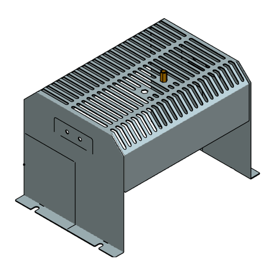
    MILLY - MINA: A + Anz. Rohrbögen = max. 4 m lokalen Normen und Vorschriften vorgenommen werden. SONIA - SEFORA: A + Anz. Rohrbögen = max. 5 m • Installation, elektrischer Anschluss, Betriebsprüfungen, Wartung und Reparaturen dürfen ausschließlich durch autorisiertes Fachpersonal durchgeführt werden, das eine ausreichende Kenntnis des Produktes...
  • Seite 19 AUSTRITTSÖFFNUNG FÜR WARMLUFT MILLY - MINA - LIA - LISA: A+B + Anz. Rohrbögen = max. 4 m SONIA - SEFORA: A+B + Anz. Rohrbögen = max. 5 m LÖSUNG 4. Der Ofen wird so installiert, dass sich der Auslass des Kanalisations- Sets an der rechten Seite des Ofens befindet.
  • Seite 20 Die beiden Halterungen (G) werden nicht mehr benötigt. - Den Auslass des Ventilators (1) am Schlauch (E) mit einem Kabelbinder LIA - LISA - SONIA - MILLY - SEFORA - MINA. (F) befestigen. - Den oberen Verschluss (2) mit den 4 mitgelieferten Schrauben (5) Abb.
  • Seite 21 SONIA - MILLY - SEFORA - MINA. - Die Schlinge mit Haken (6) an den angegebenen Stellen anbringen LIA - LISA - SONIA - MILLY - SEFORA - MINA. und das verkabelte Kabel durchführen. - Mit einer Zange die seitliche Lasche in der Schutzabdeckung (3) wie Abb.
  • Seite 22: Zusatzbeschreibung

    LIA - LISA - SONIA - MILLY - SEFORA - MINA. Abb. 25 - Stecken Sie die Klemme mit 2 STIFTEN am anderen Ende des Kabels in der Position AUX 1 an der Platine, wie auf im elektrischen Schaltplan des Ofens angegeben, ein.
  • Seite 23: Belangrijke Aanwijzingen

    MILLY - MINA - LIA - LISA: A+B + n bochten = 4 m max. zijn en over de nodige kennis van het product beschikken. SONIA - SEFORA: A+B + n bochten = 5 m max. • De afbeeldingen die in dit boekje staan zijn bedoeld ter verduidelijking,...
  • Seite 24 MILLY - MINA - LIA - LISA: A+B + n bochten = 4 m max. Fig. 7 SONIA - SEFORA: A+B + n bochten = 5 m max. WARME LUCHTUITSTROOMOPENING OPLOSSING 4 Het toestel wordt geïnstalleerd met de afvoer van de kanaliseringskit aan de rechterzijkant.
  • Seite 25 Fig. 8 De twee steunen (G) mogen weggegooid worden. LIA - LISA - SONIA - MILLY - SEFORA - MINA. - Maak de afsluiting aan de bovenkant (2) vast met de 4 bijgeleverde schroeven (5). Plaats de pijlen op het element zoals hiernaast afgebeeld.
  • Seite 26 DT2034215-00 SONIA - MILLY - SEFORA - MINA. LIA - LISA - SONIA - MILLY - SEFORA - MINA. - Plaats de haken met de koppeling (6) in de aangegeven punten en - Plooi met een tang het klepje dat zich op de zijkant van de bescherming schuif de kabel erdoor.
  • Seite 27 Fig. 25 DT2034069-00 LIA - LISA - SONIA - MILLY - SEFORA - MINA. - Maak de 2-pins klem vast aan het andere uiteinde van de kabel in de positie AUX 1 op de kaart, weergegeven op het schema voor de elektrische installatie van de kachel.
  • Seite 28: Indicaciones Importantes

    MILLY - MINA - LIA - LISA: A + n codos = 4 m máx. nacionales, así como los reglamentos locales. SONIA - SEFORA: A + n codos = 5 m máx. • La instalación, la conexión eléctrica, la prueba de funcionamiento, el mantenimiento y las reparaciones son operaciones que deben ser realizadas únicamente por personal cualificado, autorizado y que...
  • Seite 29 DEL AIRE CALIENTE MILLY - MINA - LIA - LISA: A+B + n codos = 4 m máx. SONIA - SEFORA: A+B + n codos = 5 m máx. OPCIÓN 4. El aparato se instala con la salida del kit de canalización en la parte lateral derecha.
  • Seite 30 Los dos soportes (G) son desechables. LIA - LISA - SONIA - MILLY - SEFORA - MINA. - Fije el cierre superior (2) con 4 de los tornillos (5) incluidos. Las flechas marcadas en la pieza deben quedar orientadas de la manera indicada al lado.
  • Seite 31 SONIA - MILLY - SEFORA - MINA. - Coloque los lazos con enganche (6) en los puntos indicados y pase el LIA - LISA - SONIA - MILLY - SEFORA - MINA. cable cableado. - Doble con un alicate la lengüeta lateral de la protección (3) tal y como Fig.
  • Seite 32: Especificaciones Adicionales

    Fig. 25 DT2034069-00 LIA - LISA - SONIA - MILLY - SEFORA - MINA. - Acople el borne de 2 PINS al otro extremo del cable cableado en la posición AUX 1 de la tarjeta, tal y como se indica en el esquema eléctrico de la estufa.
  • Seite 33: Informações Importantes

    MILLY - MINA - LIA - LISA: A + n curvas = 4 m máx à disposição. SONIA - SEFORA: A + n curvas = 5 m máx • A instalação e utilização do aparelho devem ser feitas de acordo com as instruções do fabricante, respeitando as disposições legislativas...
  • Seite 34: Instalação

    - Tire o painel lateral superior direito (A) seguindo as instruções alta; referidas no parágrafo “REMOÇÃO REVESTIMENTO” do manual de - A manga isolante deve ter peso específico igual ou superior a 50 kg/ instruções anexado ao produto. m³ com uma temperatura limite de utilização de pelo menos 250°C.
  • Seite 35 - Fixe a saída do ventilador (1) ao tubo flexível (E) através de uma Os dois suportes (G) são irrecuperáveis. abraçadeira (F). Fig. 14 - Fixe o fecho superior (2) com 4 parafusos (5) em dotação. Posicione as setas presentes na peça como representado ao lado. Fig. 11 DT2034128-01 DT2034126-00 H07031710 / DT2002252 –...
  • Seite 36 - Posicione os cordões com engate (6) nos pontos indicados e faça passar o cabo cablado. DT2034215-00 Fig. 20 LIA - LISA - SONIA - MILLY - SEFORA - MINA. - Dobre com uma pinça a lingueta lateral presente na proteção (3) como indicado ao lado. Fig. 16 DT2034119-00 Verifique que o cabo cablado não entre em contacto com as...
  • Seite 37 LIA - LISA - SONIA - MILLY - SEFORA - MINA. - Empurre a sonda para dentro do tubo de maneira que não toque o - Ligue o terminal de 2 PINOS na outra extremidade do cabo cablado outro parafuso.
  • Seite 38 DT2034073-01 ITALIANO ENGLISH FRANÇAIS DEUTSCH Legenda componenti Key to parts Légende composants Bestandteilangabe Ventilatore ambiente Room fan Ventilateur ambiant Raumluftgebläse Morsetto ponte Clamp Borne à boucle Brückenklemme Scheda madre Motherboard Carte de base Hauptsteuerung Feinsicherung 5x20 Fusibile 5x20 500mAL250V Fuse 5x20 500mAL250V Fusible 5x20 500mAL250V 500mAL250V Legenda colori...
  • Seite 39 H07031710 / DT2002252 – 04...
  • Seite 40 Via Montello, 22 31011 Casella d’Asolo (TV) - ITALY Tel. +39.04235271 - Fax +39.042355178 www.superiorstufe.com e-mail: info@superiorstufe.com...

Diese Anleitung auch für:

MillySeforaMinaLiaLisa

Inhaltsverzeichnis