Herunterladen Inhalt Inhalt Diese Seite drucken
Vorschau ausblenden Andere Handbücher für BR 41:
Inhaltsverzeichnis

Werbung

Verfügbare Sprachen
  • DE

Verfügbare Sprachen

  • DEUTSCH, seite 8
Modell der Dampflok BR 41
22927

Werbung

Inhaltsverzeichnis
loading

Inhaltszusammenfassung für Trix BR 41

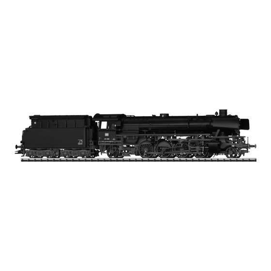
  • Seite 1 Modell der Dampflok BR 41 22927...
  • Seite 2: Inhaltsverzeichnis

    Seite Page Inhaltsverzeichnis: Sommaire : Informationen zum Vorbild Informations concernant la locomotive réelle Betriebshinweise Remarques sur l’exploitation Sicherheitshinweise Remarques importantes sur la sécurité Wichtige Hinweise Information importante Funktionen Fonction Schaltbare Funktionen Fonctions commutables CVs et paramètres CVs und Parameter Ergänzendes Zubehör Accessoires complémentaires Wartung und Instandhaltung Entretien et maintien...
  • Seite 3 Página Innehållsförteckning: Sida Indice de contenido: Instrucciones de uso Driftanvisningar Säkerhetsanvisningar Aviso de seguridad Notas importantes Viktig information Funciones Funktioner Kopplingsbara funktioner Funciones posibles CVs y parámetros CV och parametrar Accesorios complementarios Ytterligare tillbehör El mantenimiento Underhåll och reparation Recambios Reservdelar Pagina Indholdsfortegnelse:...
  • Seite 4: Informationen Zum Vorbild

    03, but it was rated for 290 pounds per square de er bei der BR 41 für 20 bar ausgelegt. Die Radsatzfahrmasse inch on the class 41. The axle load could be set at 18 or 20 metric konnte wahlweise auf 18 t oder 20 t eingestellt werden.
  • Seite 5 était de conception nouvelle, la chaudière était la même que cel- den in 1936 door Schwartzkopff geleverd. Het onderstel was een le de la série 03, mais à la différence de la BR 41, elle était prévue nieuwe ontwikkeling, de ketel was dezelfde als die van de serie pour 20 bars.
  • Seite 6: Betriebshinweise

    Kolbenstangenschutzrohr einsetzen How to install the cylinder rot protector Insérer le tube de protection de la lige de piston Beschermbuis cilinderstang plaatsen Colocar el tubo protector de la biela Radius > 500 mm Installazione del tubetto di protezione per l’asta dello stantuffo Kolvstångsskyddsröret monteras Cylinderstang-beskyttelsesør indsættes...
  • Seite 7 Kurzkupplung zwischen Lok und Tender verstellbar Close coupling between locomotive and tender is adjustable Attelage court réglable entre locomotive et tender Kortkoppeling tussen loc en tender is verstelbaar El enganche corto ajustable entre locomotora y ténder Aggancio corto regolabile tra locomotiva e tender Kortkopplet mellan lok och tender kan regleras Kortkobling mellem lok og tender indstillelig Radius >...
  • Seite 8: Sicherheitshinweise

    Sicherheitshinweise Funktionen • Die Lok darf nur mit einem dafür bestimmten Betriebssystem • Eingebaute Elektronik zum wahlweisen Betrieb mit konventio- eingesetzt werden. nellem Gleichstrom-Fahrgerät, Trix Systems oder Digitalsyste- men nach NMRA-Norm. • Analog max. 15 Volt =, digital max. 22 Volt ~. • Automatische Systemerkennung zwischen Digital- und • Die Lok darf nur aus als einer Leistungsquelle versorgt Analog-Betrieb. werden. • Der volle Funktionsumfang ist nur unter Trix Systems und • Beachten Sie unbedingt die Sicherheitshinweise in der unter DCC verfügbar. Bedienungsanleitung zu Ihrem Betriebssystem. • Eingebaute, fahrtrichtungsabhängige Stirnbeleuchtung. • Für den konventionellen Betrieb der Lok muss das Anschluss- Im Digitalbetrieb schaltbar.
  • Seite 9: Schaltbare Funktionen

    f0 f8 f0 - f3 f4 - f7 Schaltbare Funktionen systems STOP mobile station Stirnbeleuchtung Funktion f0 Funktion f0 Rauchgenerator — Funktion f1 Funktion f1 Funktion f1 Geräusch: Betriebsgeräusch — Funktion f2 Funktion f2 Funktion f2 Geräusch: Lokpfeife — Funktion f3 Funktion f3 Funktion f3 ABV, aus...
  • Seite 10: Cvs Und Parameter

    Bedeutung Wert DCC ab Werk Adresse 1 - 127 PoM Minimalgeschwindigkeit 0 - 255 PoM Anfahrverzögerung 0 - 255 PoM Bremsverzögerung 0 - 255 PoM Maximalgeschwindigkeit 0 - 255 Werkreset/Herstellerkennung PoM Funktionen F1 - F8 im Analogbetrieb 0 - 255 PoM Funktionen F9 - F15 und Licht im Analogbetrieb 0 - 255 Erweiterte Adresse (oberer Teil)
  • Seite 11: Safety Warnings

    Safety Notes Functions • This locomotive is only to be used with the operating system • Built-in electronic circuit for operation with a conventional DC power pack, Trix Systems or NMRA DCC digital systems. it is designed for. • Analog max. 15 volts DC, digital max. 22 volts AC. • Automatic system recognition between digital and analog operation. • This locomotive must never be supplied with power from more than one power pack. • The full range of functions is only available under Trix Sys- tems and under DCC. • Please make note of the safety notes in the instructions for your operating system.
  • Seite 12: Controllable Functions

    f0 f8 f0 - f3 f4 - f7 Controllable Functions systems STOP mobile station Headlights Function f0 Function f0 Smoke generator — Function f1 Function f1 Function f1 Sound effect: Operating sounds — Function f2 Function f2 Function f2 Sound effect: Locomotive whistle —...
  • Seite 13: Cvs And Parameters

    Discription DCC Value Factory-Set Address 1 - 127 PoM Minimum Speed 0 - 255 PoM Acceleration delay 0 - 255 PoM Braking delay 0 - 255 PoM Maximum speed 0 - 255 Factory Reset / Manufacturer Recognition PoM Functions F1 - F8 in analog operation 0 - 255 PoM Functions F9 - F15 and lights in analog operation 0 - 255...
  • Seite 14: Remarques Importantes Sur La Sécurité

    Fonctionnement • La locomotive ne peut être utilisée qu‘avec le système • Electronique intégrée pour exploitation au choix avec transfor- d‘exploitation indiqué. mateur-régulateur conventionnel délivrant du courant continu, avec Trix Systems ou avec des systèmes de conduite digitale • Analogique max. 15 Volt =, digital max. 22 Volt ~. conformes aux normes NMRA. • La locomotive ne peut pas être alimentée électriquement par • Reconnaissance automatique du système entre exploitations plus d‘une source de courant à la fois.
  • Seite 15: Fonctions Commutables

    f0 f8 f0 - f3 f4 - f7 Fonctions commutables systems STOP mobile station Fanal activé Fonction f0 Fonction f0 Générateur de fumée — Fonction f1 Fonction f1 Fonction f1 Bruitage : Bruit d’exploitation — Fonction f2 Fonction f2 Fonction f2 Bruitage : Sifflet locomotive —...
  • Seite 16: Cvs Et Paramètres

    Affectation DCC Valeur Parm. Usine Adresse 1 - 127 PoM Vitesse minimale 0 - 255 PoM Temporisation d‘accélération 0 - 255 PoM Temporisation de freinage 0 - 255 PoM Vitesse maximale 0 - 255 Réinitialisation d’usine/identification du fabricant PoM Fonctions F1 - F8 en mode analog 0 - 255 PoM Fonctions F9 - F15 et éclairage en mode analog 0 - 255...
  • Seite 17: Veiligheidsvoorschriften

    Veiligheidsvoorschriften Functies • De loc mag alleen met een daarvoor bestemd bedrijfssysteem • Ingebouwde elektronica die het mogelijk maakt om naar gebruikt worden. keuze met, een conventionele gelijkstroomrijregelaar, Trix Systems of digitaalsysteem volgens NMRA-norm te rijden. • Analoog max. 15 Volt =, digitaal max. 22 Volt ~. • Automatische systeemherkenning tussen digitaal- en ana- • De loc mag niet vanuit meer dan één stroomvoorziening loogbedrijf. gelijktijdig gevoed worden. • De volledige toegang tot alle functies is alleen mogelijk met • Lees ook aandachtig de veiligheidsvoorschriften in de Trix Systems of met DCC bedrijf.
  • Seite 18: Schakelbare Functies

    f0 f8 f0 - f3 f4 - f7 Schakelbare functies systems STOP mobile station Frontverlichting Functie f0 Functie f0 Rookgenerator — Functie f1 Functie f1 Functie f1 Geluid: bedrijfsgeluiden — Functie f2 Functie f2 Functie f2 Geluid: locfluit — Functie f3 Functie f3 Functie f3 ABV, uit...
  • Seite 19: Cv's En Parameter

    Betekenis Waarde DCC Af fabriek Adres 1 - 127 PoM Minimale snelheid 0 - 255 PoM Optrekvertraging 0 - 255 PoM Afremvertraging 0 - 255 PoM Maximumsnelheid 0 - 255 Fabrieksinstelling/fabriekherkenning PoM functies F1 - F8 in analoogbedrijf 0 - 255 PoM functies F9 - F15 en licht in analoogbedrijf 0 - 255 Uitgebreld adres (bovenste gedeelte)
  • Seite 20: Aviso De Seguridad

    Aviso de seguridad Funciones • La locomotora solamente debe funcionar en el sistema que le • Electrónica incorporada para un funcionamiento a discreción corresponda. en corriente continua convencional, Trix Systems o sistemas Digital según las normas NMRA. • Analógicas máx. 15 voltios =, digitales máx. 22 voltios ~. • Detección automática del sistema entre los modos digital y • La locomotora no deberá recibir corriente más que de un solo analógico. punto de abasto a la vez. • La plena funcionalidad de funciones está disponible sólo en • Observe necesariamente los avisos de seguridad indicados Trix Systems y en DCC.
  • Seite 21: Funciones Posibles

    f0 f8 f0 - f3 f4 - f7 Funciones posibles systems STOP mobile station Faros frontales encendido Función f0 Función f0 Generador de humo — Función f1 Función f1 Función f1 Ruido: ruido de explotación — Función f2 Función f2 Función f2 Ruido del silbido de la locomotora — Función f3 Función f3 Función f3 ABV, apagado —...
  • Seite 22: Cvs Y Parámetros

    Significado Valor DCC Preselección Códigos 1 - 127 PoM Velocidad mínima 0 - 255 PoM Arranque progresivo 0 - 255 PoM Frenado progresivo 0 - 255 PoM Velocidad máxima 0 - 255 Reset de fábrica/código de fabricante PoM Funciones F1 - F8 en el modo analógico 0 - 255 PoM Funciones F9 - F15 y luces en el modo analógico 0 - 255 Dirección ampliada (parte superior) CV 29, Bit 5 =1...
  • Seite 23: Avvertenze Per La Sicurezza

    Funzioni • Tale locomotiva deve venire impiegata soltanto con un siste- • Modulo elettronico incorporato per il funzionamento a scelta ma di esercizio prestabilito a questo scopo. con un tradizionale regolatore di marcia in corrente continua, Trix Systems oppure sistemi digitali in base alla normativa • Analogico max. 15 Volt =, digitale max. 22 Volt ~. NMRA. • La locomotiva non deve venire alimentata nello stesso tempo • Riconoscimento automatico del sistema tra esercizio Digital con più di una sorgente di potenza.
  • Seite 24: Funzioni Commutabili

    f0 f8 f0 - f3 f4 - f7 Funzioni commutabili systems STOP mobile station Illuminazione di testa accesa Funzione f0 Funzione f0 Apparato fumogeno — Funzione f1 Funzione f1 Funzione f1 Rumore: rumori di esercizio — Funzione f2 Funzione f2 Funzione f2 Rumore: fischio da locomotiva —...
  • Seite 25: Cv E Parametri

    Significato Valore DCC Di fabbrica Indirizzo 1 - 127 PoM Velocità minima 0 - 255 PoM Ritardo di avviamento 0 - 255 PoM Ritardo di frenatura 0 - 255 PoM Velocità massima 0 - 255 Ripristino di fabbrica/Identificazione di produzione PoM Funzioni F1 - F8 in esercizio analogico 0 - 255 PoM Funzioni F9 - F15 e luci in esercizio analogico...
  • Seite 26: Säkerhetsanvisningar

    Säkerhetsanvisningar Funktioner • Loket får endast köras med därtill avsett driftsystem. • Inbyggd elektronik för valfri drift med konventionell likströmskörenhet, Trix Systems eller Digitalsystem enligt • Analog max. 15 Volt =, digital max. 22 Volt ~. NMRA-standard. • Loket får inte samtidigt försörjas av mer än en kraftkälla. • Automatisk system-igenkänning mellan digital- och analog- • Beakta alltid säkerhetsanvisningarna i bruksanvisningen som trafik. hör till respektive driftsystemet. • Fullständigt funktionsomfång erhålls endast vid användning • När den motorförsedda lokdelen ska köras med konventionell av Trix Systems eller DCC. drift måste anlutningsskenan vara avstörd. Till detta använder • Körriktningsberoende frontbelysning.
  • Seite 27: Kopplingsbara Funktioner

    f0 f8 f0 - f3 f4 - f7 Kopplingsbara funktioner systems STOP mobile station Frontstrålkastare till Funktion f0 Funktion f0 Röksats — Funktion f1 Funktion f1 Funktion f1 Ljud: Trafikljud — Funktion f2 Funktion f2 Funktion f2 Ljud: Lokvissla — Funktion f3 Funktion f3 Funktion f3...
  • Seite 28: Cv Och Parametrar

    Betydelse Värde DCC Fabr.inst. Adress 1 - 127 PoM Minimihastighet 0 - 255 PoM Accelerationsfördröjning 0 - 255 PoM Bromsfördröjning 0 - 255 PoM Maxfart 0 - 255 Återställning till fabrikens/tillverkarens ursprungsinställningar PoM Funktion F1 – F8 vid analog drift 0 - 255 PoM Funktion F9 –...
  • Seite 29: Vink Om Sikkerhed

    Vink om sikkerhed Funktioner • Lokomotivet må kun anvendes med et driftssystem, der er • Indbygget elektronik til valgfri drift med konventionelt jæv- beregnet dertil. nstrømskøreudstyr, Trix Systems eller Digitalsystemer efter NMRA-norm. • Analog max. 15 Volt =, digital max. 22 Volt ~. • Automatisk systemgenkendelse mellem digital- og ana- • Lokomotivet må ikke forsynes fra mere end én strømkilde ad logdrift. gangen. • Det komplette funktionsomfang er kun til rådighed under Trix • Vær under alle omstændigheder opmærksom på de vink om Systems og under DCC. sikkerhed, som findes i brugsanvisningen for Deres driftssy- stem.
  • Seite 30: Styrbare Funktioner

    f0 f8 f0 - f3 f4 - f7 Styrbare funktioner systems STOP mobile station Frontbelysning tændt Funktion f0 Funktion f0 Røggenerator — Funktion f1 Funktion f1 Funktion f1 Lyd: Driftslyd — Funktion f2 Funktion f2 Funktion f2 Lyd: Lokomotivfløjte — Funktion f3 Funktion f3 Funktion f3...
  • Seite 31: Cv'er Og Parametre

    Betydning Værdi DCC Fra fabrikken Adresse 1 - 127 PoM Mindstehastighed 0 - 255 PoM Kørselsforsinkelse 0 - 255 PoM Bremseforsinkelse 0 - 255 PoM Maksimalhastighed 0 - 255 Fabriksnulstilling/Producentmærke PoM Funktionerne F1 - F8 i analogdrift 0 - 255 PoM Funktionerne F9 - F15 og lys i analogdrift 0 - 255 Udvidet adresse (Øverste del)
  • Seite 32: Ergänzendes Zubehör

    Potentielle Fehlerquellen beim Rauchgenerator • Der Rauchgenerator darf nur maximal halb mit Rauchöl gefüllt sein. • Im Rauchgenerator darf sich keine Luftblase befinden. 7226 • Der Anschlussdraht an der Unterseite des Rauchgenerators muss sicheren Kontakt zur Anschlussfeder im Lokomotiv- Fahrgestell besitzen. Notfalls Anschlussdraht entsprechend nebenstehender Zeichnung justieren. Potential Problems with the Smoke Generator • The smoke generator cannot be filled any more than halfway with smoke fluid. • There should not be any air bubbles in the smoke generator. • The connecting wire on the underside of the smoke generator must have a clean contact with the connection field in the locomotive’s frame.
  • Seite 33 Causes d‘erreurs potentielles Avec le générateur fumigène Potenziali origini di guasti nel caso dell’apparato fumogeno • Le générateur fumigène ne peut pas être rempli de liquide • L’apparato fumogeno come massimo deve essere riempito fumigène au-delà de la moitié du tube. solamente a metà di olio vaporizzabile. • Aucune bulle d‘air ne peut se trouver dans le générateur • Nell’apparato fumogeno non deve trovarsi alcuna bolla d’aria. fumigène. • Il conduttore di alimentazione sulla faccia inferiore • Le câble de raccordement raccordé à la face inférieure dell’apparato fumogeno deve possedere un sicuro contatto du fumigène doit posséder un contact sûr avec le ressort verso la molla di connessione nel telaio della locomotiva.
  • Seite 37 Trix 66626...
  • Seite 43 1 Windleitbleche E178 852 2 Motor E163 818 3 Schraube E786 341 4 Decoder 166 970 5 Sechskantansatzschraube E223 431 6 Sechskantansatzschraube E143 781 7 Linsenschraube E786 540 8 Vorlaufgestell komplett E178 855 9 Laufgestell komplett E166 964 10 Haftreifen E220 530 11 Deichsel, Zugstange E178 856...
  • Seite 44 (1) This device may not cause harmful interference, and (2) this device must accept any interference received, including interference that may cause undesired operation. Gebr. Märklin & Cie. GmbH Stuttgarter Straße 55 - 57 73033 Göppingen 167604/0112/Sm1Ef Deutschland Änderungen vorbehalten http://www.maerklin.com/en/imprint.html www.trix.de © Gebr. Märklin & Cie. GmbH...

Inhaltsverzeichnis