Futurelight DMB-160 Bedienungsanleitung
Led moving head

Verwandte Anleitungen für Futurelight DMB-160


Inhaltszusammenfassung für Futurelight DMB-160
- Seite 1 BEDIENUNGSANLEITUNG USER MANUAL DMB-160 LED Moving Head © Copyright Für weiteren Gebrauch aufbewahren! Nachdruck verboten! Keep this manual for future needs! Reproduction prohibited!
-
Seite 2: Inhaltsverzeichnis
Features ................................. 8 Geräteübersicht .............................. 9 INSTALLATION .............................. 10 Projektormontage ............................10 Einbau des optionalen drahtlos-Empfängers für WDMX-Betrieb (FUTURELIGHT WDR-G4) ....13 Anschluss an den DMX-512 Controller / Verbindung Projektor – Projektor ..........14 Anschluss ans Netz ............................15 BEDIENUNG ..............................15 Standalone-Betrieb ............................ - Seite 3 Features ............................... 36 Overview ..............................37 INSTALLATION .............................. 38 Rigging ................................. 38 Installation of the optional wireless receiver for WDMX-operation (FUTURELIGHT WDR-G4) ....41 DMX-512 connection / connection between fixtures ..................42 Connection with the mains ........................... 43 OPERATION ..............................43 Stand Alone operation ..........................
-
Seite 4: Einführung
- sich die letzte Version der Anleitung im Internet herunter laden EINFÜHRUNG Wir freuen uns, dass Sie sich für einen FUTURELIGHT DMB-160 entschieden haben. Sie haben hiermit ein leistungsstarkes und vielseitiges Gerät erworben. Nehmen Sie den DMB-160 aus der Verpackung. -
Seite 5: Sicherheitshinweise
SICHERHEITSHINWEISE ACHTUNG! Seien Sie besonders vorsichtig beim Umgang mit gefährlicher Netzspannung. Bei die- ser Spannung können Sie einen lebensgefährlichen elektrischen Schlag erhalten! Dieses Gerät hat das Werk in sicherheitstechnisch einwandfreiem Zustand verlassen. Um diesen Zustand zu erhalten und einen gefahrlosen Betrieb sicherzustellen, muss der Anwender die Sicherheitshinweise und die Warnvermerke unbedingt beachten, die in dieser Bedienungsanleitung enthalten sind. -
Seite 6: Bestimmungsgemäße Verwendung
Es dürfen unter keinen Umständen Flüssigkeiten aller Art in Steckdosen, Steckverbindungen oder in irgendwelche Geräteöffnungen oder Geräteritzen eindringen. Besteht der Verdacht, dass - auch nur minimale - Flüssigkeit in das Gerät eingedrungen sein könnte, muss das Gerät sofort allpolig vom Netz getrennt werden. - Seite 7 Dieses Gerät darf nur in einer Höhenlage zwischen -20 und 2000 m über NN betrieben werden. Verwenden Sie das Gerät nicht bei Gewitter. Überspannung könnte das Gerät zerstören. Das Gerät bei Gewitter allpolig vom Netz trennen (Netzstecker ziehen). - - -m Das Bildzeichen bezeichnet den Mindestabstand zu beleuchteten Gegenständen.
-
Seite 8: Gerätebeschreibung
GERÄTEBESCHREIBUNG Features LED-Beam mit 150-W-COB-LED und den Vorzügen eines Moving-Heads • Mit Glaslinse • Extrem hohe Lichtausbeute • Sehr enger Abstrahlwinkel von 3° • Optionaler Drahtlos-Empfänger für WDMX-Betrieb (Wireless Solution - made in Sweden) kann nachgerüstet werden • Flickerfreie Projektion •... -
Seite 9: Geräteübersicht
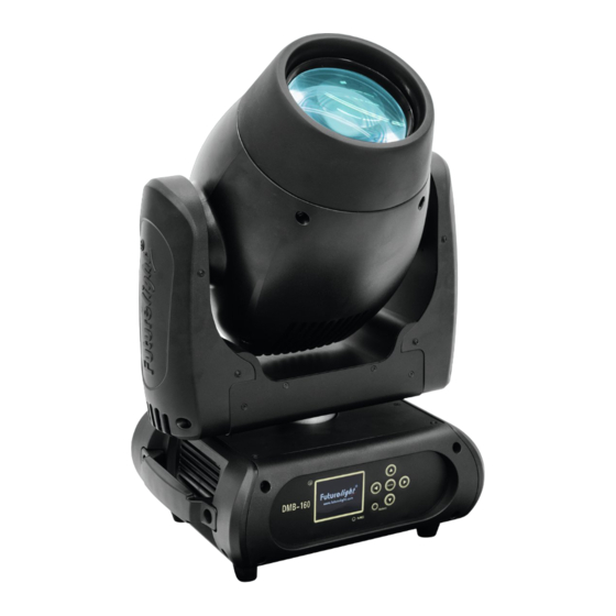
Geräteübersicht (1) Objektivlinse (2) Projektorarm (3) Base (4) Tragegriff (5) Gummifuß (6) Drahtlosanzeige (7) Display (8) Fangseilöse (9) Mikrofon (10) ESDC-Schalter (11) Pfeil-Taste nach links (12) Pfeil-Taste nach unten (13) Enter-Taste (14) Pfeil-Taste nach rechts (15) Pfeil-Taste nach oben (16) 3-poliger DMX-Eingangsstecker (17) 5-poliger DMX-Eingangsstecker (18) 3-polige DMX-Ausgangsbuchse (19) 5-polige DMX-Ausgangsbuchse... -
Seite 10: Installation
INSTALLATION Projektormontage Die Aufhängevorrichtungen des Projektors muss so gebaut und bemessen sein, dass sie 1 Stunde lang ohne dauernde schädliche Deformierung das 10-fache der Nutzlast aushalten kann. Die Installation muss immer mit einer zweiten, unabhängigen Aufhängung, z. B. einem geeigneten Fangnetz, erfolgen. - Seite 11 ACHTUNG! Montieren Sie den Projektor ausschließlich über einen geeigneten Haken. Bitte beachten Sie auch die Installationshinweise auf der Unterseite der Base. Achten Sie darauf, dass das Gerät sicher befestigt wird. Vergewissern Sie sich, dass die Verankerung stabil ist. Die Projektorbase lässt sich auf zwei verschiedene Arten montieren. Das Gerät kann direkt auf den Boden gestellt werden oder in jeder möglichen Position im Trussing...
- Seite 12 (1) Omega-Halter (2) Haken (3) Sicherheitsfangseil (4) Schnellverschluss Verschrauben Sie einen Haken über eine M10 Schraube und selbstsichernde Mutter mit dem Omega-Halter. Führen Sie die beiden Schnellverschlüsse des Omega-Halters in die dafür vorgesehenen Öffnungen Geräteunterseite ein. Drehen Schnellverschlüsse im Uhrzeigersinn bis zum Anschlag fest. 12/59 00085201, Version 1.1...
-
Seite 13: Einbau Des Optionalen Drahtlos-Empfängers Für Wdmx-Betrieb (Futurelight Wdr-G4)
Einbau des optionalen drahtlos-Empfängers für WDMX-Betrieb (FUTURELIGHT WDR-G4) ACHTUNG! Vor Einbau des Moduls das Gerät vom Netz trennen. Gefahr eines elektrischen Schlages! Installationsschritte 1. Nehmen Sie den Drahtlos-DMX-Empfänger aus der Verpackung. Das Modul besteht aus einer Stabantenne mit Gewinde, der Wireless-Platine und einem Verbindungskabel. -
Seite 14: Anschluss An Den Dmx-512 Controller / Verbindung Projektor - Projektor
Anschluss an den DMX-512 Controller / Verbindung Projektor – Projektor Achten Sie darauf, dass die Adern der Datenleitung an keiner Stelle miteinander in Kontakt treten. Die Geräte werden ansonsten nicht bzw. nicht korrekt funktionieren. Beachten Sie, dass die Startadresse abhängig vom verwendeten Controller ist. Unbedingt Bedienungsanleitung des verwendeten Controllers beachten. -
Seite 15: Anschluss Ans Netz
BEDIENUNG Über den Netzschalter lässt sich das Gerät ein- bzw. ausschalten. Wenn Sie das Gerät an die Spannungsversorgung angeschlossen haben, nimmt der DMB-160 den Betrieb auf. Während des Reset justieren sich die Motoren aus und das Gerät ist danach betriebsbereit. -
Seite 16: Dmx-Protokoll
Bitte vergewissern Sie sich, dass sich die Steuerkanäle nicht mit anderen Geräten überlappen, damit der DMB-160 korrekt und unabhängig von anderen Geräten in der DMX-Kette funktioniert. Werden mehrere DMB-160 auf eine Adresse definiert, arbeiten sie synchron. Drücken Sie die Up/Down-Tasten, um die gewünschte Startadresse einzustellen. Nun können Sie den DMB- 160 über Ihren Controller ansteuern. - Seite 17 100% Keine Funktion Shutter, Strobe Normale Shutter Funktionen Geschlossen Strobe-Effekt mit zunehmender Geschwindigkeit 100% Offen Öffnender Puls-Effekt Geschlossen Puls-Effekt mit zunehmender Geschwindigkeit 100% Offen Schließender Puls-Effekt Geschlossen Puls-Effekt mit zunehmender Geschwindigkeit 100% Offen Strobe-Effekt über Zufallsgenerator Geschlossen Strobe-Effekt mit zunehmender Geschwindigkeit 100% Offen...
- Seite 18 Position 3 Position 4 Position 5 Position 6 Position 7 Position 8 Position 9 Position 10 Position 11 Position 12 Position 13 100% Position 14 Rainboweffekt vorwärts 100% Mit zunehmender Geschwindigkeit Rainboweffekt rückwärts 100% Mit zunehmender Geschwindigkeit Farbwechsel an jeder Position 100% Positionierung von 0 - 360 Grad Schneller Farbsprung...
- Seite 19 Position 25 Position 26 Position 27 100% Position 28 Farbrad Normaler Farbwechsel Offen Position 1 Position 2 Position 3 Position 4 Position 5 Position 6 Position 7 Position 8 Position 9 Position 10 Position 11 Position 12 Position 13 Position 14 Blackout bei Farbwechsel Offen Position 1...
- Seite 20 Rainboweffekt vorwärts Mit zunehmender Geschwindigkeit Rainboweffekt rückwärts 100% Mit zunehmender Geschwindigkeit Funktion statisches Goborad, Gobo-Shake Normaler Gobowechsel Blackout bei Gobowechsel Rotierendes Goborad vorwärts Rotierendes Goborad rückwärts Gobowechsel an jeder Position Gobo-Shake 100% Keine Funktion Statisches Goborad, Gobo-Shake Normaler Gobowechsel / Blackout bei Gobowechsel / Gobo-Shake S/F Offen S/F Position 1...
- Seite 21 Position 3 Position 4 Position 5 Position 6 Position 7 Position 8 Position 9 Position 10 Position 11 Position 12 Position 13 Position 14 Position 15 Position 16 Position 17 Blackout bei Gobowechsel Offen Position 1 Position 2 Position 3 Position 4 Position 5 Position 6...
- Seite 22 Position 10 Position 11 Position 12 Position 13 Position 14 Position 15 Position 16 Position 17 Rotierendes Goborad vorwärts Stop Mit zunehmender Geschwindigkeit Rotierendes Goborad rückwärts Stop 100% Mit zunehmender Geschwindigkeit Prisma Offen 11 14 6-fach-linear-Prisma 8-Facetten-Prisma 100% Frost Prismenrotation Prismenrotation an jeder Position Positionierung von 0 - 360 Grad Rotierendes Prisma vorwärts...
-
Seite 23: Control Board
Control Board Das Control Board bietet mehrere Möglichkeiten: so lassen sich z. B. die DMX-Startadresse eingeben, das vorprogrammierte Programm abspielen oder ein Reset durchführen. Drücken Sie die Enter-Taste, so dass sich das Display einschaltet. Durch Drücken der geeigneten Pfeil- Taste (nach unten, nach oben, nach links und nach rechts) können Sie sich im Hauptmenü bewegen. Zur Auswahl des gewünschten Menüpunktes drücken Sie die Enter-Taste. -
Seite 24: Connect
Standard Extended Benutzerdefinierte User Mode Basic-8bit Kanalreihenfolge Basic-16bit Users User Max Channel = XX Preset-Benutzerd. Edit User PAN = CH01 ... Effektradjustierung; --Password-- Password=XXX Calibration Standardposition Color ... Color =XXX ... Passwort „050“ Name Name --Password-- Passwort „050“ Fixture ID ... -
Seite 25: Light
Light Max Temperatur Mit dieser Funktion kann das Gerät so programmiert werden, dass die LED automatisch abgeschaltet wird, wenn eine bestimmte Innentemperatur erreicht wird. Drücken Sie die Up/Down-Tasten zur Auswahl der maximalen Innentemperatur zwischen 80 °C und 139 °C. Die normale Betriebstemperatur sollte unter 90 °C liegen. - Seite 26 Display-Helligkeit Mit der Funktion „Display Bright“ lässt sich die Display-Helligkeit einstellen. Markennamen anzeigen Mit der Funktion „Brand Show“ kann der Markenname "FUTURELIGHT" angezeigt oder ausgeblendet werden. Tastensperre Mit der Funktion „Key Lock“ können Sie die Tasten des Control Boards sperren, um z.B. ein Eingreifen Unbefugter zu verhindern.
-
Seite 27: Program
Users Benutzerdefinierte Kanalreihenfolge Mit dieser Funktion lassen sich benutzerdefinierte Kanalreihenfolgen abspeichern. Preset-Benutzerdefinition Mit dieser Funktion lässt sich Preset-Benutzerdefinition abspeichern. Calibration Effektradjustierung Mit dieser Funktion lassen sich die Effekträder auf die korrekten Ausgangspositionen kalibrieren. Das Passwort für diese Funktion ist „050“. Fixture ID Mit dieser Funktion können Sie diverse Menüpunkte per RDM abrufen. - Seite 28 Musiksteuerung Mit dieser Funktion lässt sich das interne Programm aufrufen. Mit dieser Funktion lassen sich die Szenen musikgesteuert abspielen. Die Auswahl „ALONE“ bedeutet Stand Alone-Modus und „MASTER“, dass das Gerät als Master-Gerät definiert wird. Programmwahl für Auto Programm Mit dieser Funktion lässt sich das Programm festlegen, das dann im Run aufgerufen wird. Programm editieren Mit dieser Funktion lassen sich die internen Programme editieren.
-
Seite 29: Fehlermeldungen
4. Programmwahl für Edit Programm • Wählen Sie “Edit Chase” durch Drücken der Up/Down-Tasten. • Drücken Sie die Enter-Taste zur Bestätigung. • Wählen Sie “Edit Chase” durch Drücken der Up/Down-Tasten. • Drücken Sie die Enter-Taste zur Bestätigung. • Drücken Sie die Up/Down-Taste, um das gewünschte spezifische Programm einzustellen. Mit dieser Funktion lassen sich spezifische Szenen in ein spezifisches Programm editieren. -
Seite 30: Reinigung Und Wartung
Die entsprechende Fehlermeldung erscheint, wenn nach dem Reset magnetisch-indizierte Fehlfunktionen an dem entsprechenden Kanalfeature vorliegen (Photodiode defekt oder der Magnet fehlt) oder der Steppermotor defekt ist (oder dessen Treiber auf der Hauptplatine). Dabei befindet sich das entsprechende Kanalfeature nach dem Reset nicht in der Vorgabeposition. Die verschiedenen Fehlermeldungen sind: Color Wheel Prism Rotation... -
Seite 31: Technische Daten
OMNITRONIC XLR Kabel 5pol 3m sw Best.-Nr. 30220768 FUTURELIGHT DES-5 Abschlussstecker 5pol Best.-Nr. 51834002 PSSO PowerCon Verbindungskabel 3x1,5 1,5m Best.-Nr. 3023503L ROADINGER Flightcase 2x DMH-90/150/DMB-60/PLB-230 Best.-Nr. 51836892 ROADINGER Flightcase 4x DMH-90/150/DMB-160/PLB-230 Best.-Nr. 51836894 FUTURELIGHT RDM PC Director USB Interface Best.-Nr. 51834860 31/59 00085201, Version 1.1... -
Seite 32: Konformität
KONFORMITÄT Bitte beachten Sie: Technische Änderungen ohne vorherige Ankündigung und Irrtum vorbehalten. 13.05.2016 © 32/59 00085201, Version 1.1...