Herunterladen Inhalt Inhalt Diese Seite drucken
Inhaltsverzeichnis

Werbung

Verfügbare Sprachen
  • DE

Verfügbare Sprachen

  • DEUTSCH, seite 68
All manuals and user guides at all-guides.com
U
ninterruptible
P
ower
S
upply
ON LINE MULTISTANDARD
5000 VA – 6000 VA MM
6500 VA – 8000 VA – 10000 VA MM/TM
Manuale d'installazione ed uso
Installation and use manual
Installations und Bedienungsanleitung
Manuel d'installation et d'utilisation
Manual de instalación y uso
Riello Power Dialog UPS available from EcoPowerSupplies
For more information visit: www.ecopowersupplies.com/riello-ups

Werbung

Inhaltsverzeichnis
loading

Inhaltszusammenfassung für Riello 5000VA

  • Seite 1 6500 VA – 8000 VA – 10000 VA MM/TM Manuale d’installazione ed uso Installation and use manual Installations und Bedienungsanleitung Manuel d’installation et d’utilisation Manual de instalación y uso Riello Power Dialog UPS available from EcoPowerSupplies For more information visit: www.ecopowersupplies.com/riello-ups...
  • Seite 2 All manuals and user guides at all-guides.com...
  • Seite 3 All manuals and user guides at all-guides.com MANUALE D’USO...
  • Seite 4 All manuals and user guides at all-guides.com NTRODUZIONE Vi ringraziamo per la scelta del nostro prodotto. La nostra azienda è prettamente specializzata nello sviluppo e nella produzione di gruppi statici di continuità (UPS). Gli UPS di questa serie sono prodotti di alta qualità, attentamente progettati e costruiti allo scopo di garantire le migliori prestazioni.
  • Seite 5: Inhaltsverzeichnis

    All manuals and user guides at all-guides.com OMMARIO RESENTAZIONE ISTE ISTA MASCHERA DISPLAY NSTALLAZIONE ’ PERTURA DELL IMBALLO E VERIFICA DEL SUO CONTENUTO ODALITÀ DI INSTALLAZIONE OLLEGAMENTI ERSIONE MONOFASE ERSIONE TRIFASE Collegamento monofase Collegamento trifase Versione con comando di By-pass remoto esterno RIMA ACCENSIONE CCENSIONE DA RETE CCENSIONE DA BATTERIA...
  • Seite 6 All manuals and user guides at all-guides.com...
  • Seite 7: Presentazione

    All manuals and user guides at all-guides.com RESENTAZIONE La nuova serie di UPS 5 - 6 monofase e 6,5 - 8 - 10 kVA trifase è stata progettata utilizzando lo stato dell’arte della tecnologia oggi disponibile, in modo da garantire all’utilizzatore le massime prestazioni. L’impiego di multiprocessori unitamente al ricorso della tecnologia a IGBT alta frequenza, consente ottime prestazioni in termini di distorsione ed efficienza.
  • Seite 8: Viste Ups

    All manuals and user guides at all-guides.com RESENTAZIONE ISTE Display Vista frontale Slot di espansione Interruttore COMUNICATION SLOT generale Remote emergency power off (R.E.P.O.) Ventola di Ventola di raffreddamento raffreddamento Prese IEC 10 A Porta di comunicazione USB Power share Porta di comunicazione RS232 Fusibile Power share...
  • Seite 9: Vista Maschera Display

    All manuals and user guides at all-guides.com RESENTAZIONE ISTA MASCHERA DISPLAY Pulsante “SEL / SET” Pulsante “STBY” Pulsante “ON” Funzionamento regolare Area di configurazione Funzionamento da rete Richiesta manutenzione Funzionamento da batteria Timer Carico alimentato da bypass Area visualizzazione misure Indicatore autonomia batteria Stand-by / allarme Indicatore livello carico...
  • Seite 10: Installazione

    All manuals and user guides at all-guides.com NSTALLAZIONE ’ PERTURA DELL IMBALLO E VERIFICA DEL SUO CONTENUTO Dopo l’apertura dell’imballo, per prima cosa procedere alla verifica del contenuto. L’imballo dovrà contenere: Cavo seriale RS232 2 Fusibili per Batterie - 14x51 mm, 50A, Manuale utente + CD-ROM software 400V Scivolo...
  • Seite 11: Modalità Di Installazione

    All manuals and user guides at all-guides.com NSTALLAZIONE ATTENZIONE: questo Gruppo di Continuità (UPS) è un prodotto che rispetta le normative vigenti di compatibilità elettromagnetica (categoria C2). In ambiente domestico può provocare interferenze radio. L’utilizzatore potrebbe dover adottare provvedimenti supplementari. L’Azienda non si assume responsabilità...
  • Seite 12: Uso

    All manuals and user guides at all-guides.com OLLEGAMENTI L’INSTALLAZIONE DEVE ESSERE ESEGUITA ESCLUSIVAMENTE DA PERSONALE QUALIFICATO. IL PRIMO COLLEGAMENTO DA EFFETTUARE E’ QUELLO DEL CONDUTTORE DI PROTEZIONE ( CAVO DI TERRA), DA INSERIRE NEL MORSETTO SIGLATO L’UPS NON DEVE FUNZIONARE SENZA IL COLLEGAMENTO CON L’IMPIANTO DI TERRA. Avvertenza: rispettando le indicazioni di neutro (N) e fase (F) relative a spine e prese, l’UPS inserito in un impianto non modifica il regime di neutro preesistente.
  • Seite 13: Versione Monofase

    All manuals and user guides at all-guides.com ERSIONE MONOFASE 1. (COLLEGAMENTO MONOFASE 5-6kVA): utilizzare 3 cavi con sezione 6 mm (TERRA, N e L) in ingresso, e 3 cavi con sezione 6 mm per l’uscita (TERRA, N e L). 2. Collegare i fili ai relativi morsetti seguendo scrupolosamente le indicazioni riportate qui di seguito: Linea di ingresso a - Assicurarsi che il magnetotermico a monte sia aperto.
  • Seite 14: Versione Trifase

    All manuals and user guides at all-guides.com ERSIONE TRIFASE Collegamento monofase 1. (COLLEGAMENTO MONOFASE 8-10kVA): utilizzare 3 cavi con sezione 10 mm (TERRA, N e L) in ingresso, e 3 cavi con sezione 10 mm per l’uscita (TERRA, N e L). (COLLEGAMENTO MONOFASE 6,5kVA): utilizzare 3 cavi con sezione 6 mm (TERRA, N e L) in ingresso, e 3 cavi con sezione 6 mm...
  • Seite 15: Collegamento Trifase

    All manuals and user guides at all-guides.com Collegamento trifase 1. (COLLEGAMENTO TRIFASE 8-10kVA): Utilizzare 3 cavi con sezione 6 mm (TERRA, L2 e L3) e 2 con sezione 10 mm (N, L1) in ingresso (N.B.: L1 e N hanno sezione maggiore perché in funzionamento da bypass devono portare tutta la corrente d’ingresso).
  • Seite 16: Versione Con Comando Di By-Pass Remoto Esterno

    All manuals and user guides at all-guides.com Versione con comando di By-pass remoto esterno Se si vuole portare all’esterno il comando di By-Pass manutenzione remoto, seguire i punti 1, 2 e 3 precedentemente spiegati. Procedere quindi nel modo seguente: 1. Seguire le istruzioni precedentemente spiegate per il collegamento, il numero e la sezione dei cavi da utilizzare, passanti attraverso i blocca guaine P1 e P2.
  • Seite 17: Prima Accensione

    All manuals and user guides at all-guides.com RIMA ACCENSIONE 1) Accertarsi che tutte le operazioni descritte nel paragrafo precedente “Collegamenti” siano state eseguite in maniera corretta. 2) Chiudere l’interruttore magnetotermico posto a monte dell’UPS. 3) Chiudere gli interruttori d’ingresso, d’uscita e inserire fusibili di batteria posti sul retro dello zainetto dell’UPS.
  • Seite 18: Indicazioni Pannello Display

    All manuals and user guides at all-guides.com NDICAZIONI PANNELLO DISPLAY In questo capitolo verranno descritte in modo approfondito tutte le informazioni che possono essere visualizzate sul display LCD. Per una maggiore comprensione, possiamo suddividere le informazioni visualizzate in tre gruppi principali: Indicatori di stato dell’UPS Area visualizzazione misure Area di configurazione...
  • Seite 19: Area Visualizzazione Misure

    All manuals and user guides at all-guides.com Area visualizzazione misure Sul display possono essere visualizzate in sequenza le più importanti misure relative all’UPS. All’accensione dell’UPS, il display visualizza il valore della tensione di rete. Per passare ad una visualizzazione differente premere il pulsante “SEL / SET” ripetutamente finché non compare la misura desiderata.
  • Seite 20: Collegamento Trifase

    All manuals and user guides at all-guides.com Collegamento trifase Di seguito sono riportati alcuni esempi: DESCRIZIONE DESCRIZIONE ESEMPIO GRAFICO ESEMPIO GRAFICO Percentuale di carica delle batterie Tensione fase 1 Tensione totale delle batterie Percentuale del carico applicato Tensione fase 2 Corrente assorbita dal carico Temperatura del sistema...
  • Seite 21: Area Di Configurazione

    All manuals and user guides at all-guides.com Area di configurazione L’area di configurazione raggruppa i parametri principali di funzionamento dell’UPS e ne visualizza lo stato attuale. I parametri contenuti in quest’area sono modificabili agendo direttamente da pannello display. PARAMETRI SETTABILI: Frequenza: Frequenza della tensione di uscita Frequenza Tensione: Tensione di uscita...
  • Seite 22: Modalità Di Funzionamento

    All manuals and user guides at all-guides.com ODALITÀ DI FUNZIONAMENTO La modalità che garantisce la massima protezione al carico è la modalità ON LINE (default), dove l’energia per il carico subisce una doppia conversione e viene ricostruita in uscita in modo perfettamente sinusoidale con frequenza e tensione fissata dal preciso controllo digitale a microprocessore in modo indipendente dall’ingresso (V.F.I.).
  • Seite 23: Configurazione Ups

    All manuals and user guides at all-guides.com ONFIGURAZIONE La seguente tabella illustra tutte le possibili configurazioni a disposizione dell’utente per adattare al meglio l’UPS alle proprie necessità. LEGENDA: Indica che la configurazione può essere modificata, oltre che dal software di configurazione, anche tramite intervento da pannello display.
  • Seite 24: Funzioni Avanzate

    All manuals and user guides at all-guides.com FUNZIONE DESCRIZIONE PREDEFINITO CONFIGURAZIONI POSSIBILI MODALITÀ Soglia di allarme • Disabilitato Seleziona il limite utente per carico Disabilitato • 0 ÷ 103 in step di 1% di sovraccarico massimo Seleziona il livello di Luminosità...
  • Seite 25: Porte Di Comunicazione

    All manuals and user guides at all-guides.com ORTE DI COMUNICAZIONE Nella parte posteriore dell’UPS (vedi Viste UPS) sono presenti le seguenti porte di comunicazione: Porta seriale, disponibile con connettore RS232 e connettore USB. NOTA: l’utilizzo di un connettore esclude automaticamente l’altro. Slot di espansione per schede di interfaccia aggiuntive COMMUNICATION SLOT.
  • Seite 26: Software

    All manuals and user guides at all-guides.com OFTWARE Software di monitoraggio e controllo Il software NetworkMonitor3 garantisce un’efficace ed intuitiva gestione dell’UPS, visualizzando tutte le più importanti informazioni come tensione di ingresso, carico applicato, capacità delle batterie. E’ inoltre in grado di eseguire in modo automatico operazioni di shutdown, invio e-mail, sms e messaggi di rete al verificarsi di particolari eventi selezionati dall’utente.
  • Seite 27: Risoluzione Problemi

    All manuals and user guides at all-guides.com ISOLUZIONE PROBLEMI Un funzionamento non regolare dell’UPS molto spesso non è indice di guasto ma è dovuto solamente a problemi banali, inconvenienti oppure distrazioni. Si consiglia pertanto di consultare attentamente la tabella sottostante che riassume informazioni utili alla risoluzione dei problemi più...
  • Seite 28 All manuals and user guides at all-guides.com ISOLUZIONE PROBLEMI PROBLEMA POSSIBILE CAUSA SOLUZIONE IL CICALINO SUONA IN MODO CONTINUO ED IL IL CARICO APPLICATO Ridurre il carico entro la soglia del 100% (o soglia DISPLAY SEGNALA UNO ALL’UPS E’ TROPPO utente in caso di codice A54).
  • Seite 29: Codici Di Allarme

    All manuals and user guides at all-guides.com ISOLUZIONE PROBLEMI ODICI DI ALLARME Utilizzando un sofisticato sistema di autodiagnosi, l’UPS è in grado di verificare e segnalare sul pannello display eventuali anomalie e/o guasti che si dovessero verificare durante il normale funzionamento dell’apparecchiatura.
  • Seite 30 All manuals and user guides at all-guides.com ISOLUZIONE PROBLEMI 3. Comandi attivi: indica la presenza di un comando remoto attivo. CODICE DESCRIZIONE Comando remoto di spegnimento Comando remoto carico su bypass Comando remoto di accensione Test batterie in esecuzione LOCK Le segnalazioni di tipo LOCK (blocchi) sono solitamente precedute da una segnalazione di allarme e, per la loro portata, comportano lo spegnimento dell’inverter e l’alimentazione del carico attraverso la linea di bypass (tale procedura è...
  • Seite 31: Tabella Dati Tecnici

    All manuals and user guides at all-guides.com ABELLA DATI TECNICI ABELLA DATI TECNICI MODELLI 5000VA 6000VA INGRESSO (1 Ø + N tensioni stellate) Tensione nominale 220 – 230 – 240 Vac monofase Range accettato 0 – 280 Vac Range di tensione per non intervento batteria...
  • Seite 32 All manuals and user guides at all-guides.com ABELLA DATI TECNICI MODELLI 6500VA 8000VA 10000VA INGRESSO (3 Ø + N tensioni stellate) Tensione nominale 220 – 230 – 240 Vac monofase / 380 – 400 – 415 Vac trifase con neutro Range accettato 0 –...
  • Seite 33: Tabella Tempi Di Sovraccarico

    All manuals and user guides at all-guides.com ABELLA DATI TECNICI ABELLA TEMPI DI SOVRACCARICO FUNZIONAMENTO DA TEMPI DI SOVRACCARICO BYPASS INVERTER Attiva bypass dopo 2 sec 100% < Load ≤ 125% In blocco dopo 60 sec In blocco dopo 120 sec Attiva bypass dopo 2 sec 125% <...
  • Seite 34 All manuals and user guides at all-guides.com...
  • Seite 35 All manuals and user guides at all-guides.com USER MANUAL...
  • Seite 36 All manuals and user guides at all-guides.com NTRODUCTION Thank you for choosing our product. The manufacturers are highly specialized in the development and production of uninterruptible power systems (UPS). The UPSs of this series are high quality products, designed and manufactured to ensure optimum performance.
  • Seite 37 All manuals and user guides at all-guides.com ONTENTS PRESENTATION UPS V IEWS DISPLAY MASK VIEW NSTALLATION PENING THE PACKAGING AND CHECKING ITS CONTENTS NSTALLATION PROCEDURES ONNECTIONS INGLE PHASE VERSION HREE PHASE VERSION Single-phase connection Three-phase connection Version with external remote By-pass command IRST SWITCHING WITCHING ON WITH MAINS POWER...
  • Seite 38 All manuals and user guides at all-guides.com...
  • Seite 39: Presentation

    All manuals and user guides at all-guides.com PRESENTATION The 5 - 6 single-phase and 6.5 - 8 - 10 kVA 3-phase UPS range has been designed using the state-of-the-art in technology available today, so as to guarantee the user maximum performance levels. The use of multiprocessors combined with high-frequency IGBT technology, grants optimum performance in terms of distortion and efficiency.
  • Seite 40: Ups Views

    All manuals and user guides at all-guides.com PRESENTATION UPS V IEWS Display Front view COMUNICATION SLOT (for expansions) Main switch Remote emergency power off (R.E.P.O.) Cooling fan Cooling fan IEC 10 A USB communication port Power share sockets RS232 communication port Power share fuse Input and output Manual bypass...
  • Seite 41: Display Mask View

    All manuals and user guides at all-guides.com PRESENTATION DISPLAY MASK VIEW “SEL / SET” button “ON” button “STBY” button Normal operation Configuration area Operation from mains Maintenance request Operation from battery Timer Load powered by the bypass Measurement display area Battery back up time indicator Stand-by/alarm Load level indicator...
  • Seite 42: Installation

    All manuals and user guides at all-guides.com NSTALLATION PENING THE PACKAGING AND CHECKING ITS CONTENTS After opening the pack, make a check of the contents first of all. The pack should contain: RS232 serial cable User manual + CD-ROM with software 2 Battery fuses - 14x51 mm, 50A, 400V Slide Jumper (only into 3phases–1phase versions)
  • Seite 43: Installation Procedures

    All manuals and user guides at all-guides.com NSTALLATION WARNING: this UPS product conforms to the current electromagnetic compatibility (EMC) regulations (C2 class). It may cause radio interference in the home environment. The user may have to adopt supplementary measures. The manufacturers cannot accept liability for damage caused by wrong connections or by operations other than those described in this manual.
  • Seite 44: Use

    All manuals and user guides at all-guides.com ONNECTIONS INSTALLATION MUST ONLY BE PERFORMED BY QUALIFIED PERSONNEL. THE FIRST CONNECTION TO BE MADE IS THAT OF THE PROTECTION CONDUCTOR (EARTH CABLE), TO THE TERMINAL MARKED THE UPS MUST NEVER BE MADE OPERATE WITHOUT A CONNECTION TO THE EARTHING SYSTEM. Warning: providing it complies with the neutral (N) and phase (F) indications for plugs and sockets, the UPS, when inserted in an installation, does not alter the existing neutral arrangements.
  • Seite 45: Single - Phase Version

    All manuals and user guides at all-guides.com INGLE PHASE VERSION 1. (SINGLE-PHASE CONNECTION 5-6kVA): use 3 cables with cross-section 6 mm (EARTH, N and L) for the input, and 3 cables with cross-section 6 mm for the output (EARTH, N and L). 2.
  • Seite 46: Three - Phase Version

    All manuals and user guides at all-guides.com HREE PHASE VERSION Single-phase connection 1. (SINGLE-PHASE CONNECTION 8-10kVA): use 3 cables of cross-section 10 mm (EARTH, N and L) for the input, and 3 cables of cross-section 10 mm for the output(EARTH, N and L). (SINGLE-PHASE CONNECTION 6.5kVA): use 3 cables of cross-section 6 mm (EARTH, N and L) for the input, and 3 cables of cross-section 6 mm...
  • Seite 47: Three-Phase Connection

    All manuals and user guides at all-guides.com Three-phase connection 1. (THREE-PHASE CONNECTION 8-10kVA): Use 3 cables of cross-section 6 mm (EARTH, L2 and L3) and 2 with cross-section 10 mm (N, L1) for the input (N.B.: L1 and N are of greater cross- section because in bypass operation they have to carry all of the input current).
  • Seite 48: Version With External Remote By-Pass Command

    All manuals and user guides at all-guides.com Version with external remote By-pass command To be able to control the remote maintenance By-Pass externally, follow points 1, 2 and 3 described above. Then proceed as follows: 11 12 13 1. Follow the instructions given above for the connection, number and cross-section of the cables to use for the power connections.
  • Seite 49: First Switching - On

    All manuals and user guides at all-guides.com IRST SWITCHING 1) Ensure that all the steps described in the previous paragraph “Connections” have been carried out correctly. 2) Close the magneto-thermal switch located upstream of the UPS. 3) Close the input and output switches and insert the battery fuses on the rear of the back-pack on the UPS.
  • Seite 50: Display Panel Indications

    All manuals and user guides at all-guides.com ISPLAY PANEL INDICATIONS This section describes in detail all the information that can be shown on the LCD display. In order to make it clearer, all the information displayed can be divided into three main groups: UPS status indicators Measurements display area Configuration area...
  • Seite 51: Measurements Display Area

    All manuals and user guides at all-guides.com Measurements display area The most important measurements regarding the UPS may be posted on the display in sequence. When the UPS is switched on, the display shows a reading of the mains voltage value. To change to a different display, press the “SEL / SET”...
  • Seite 52: Three-Phase Connection

    All manuals and user guides at all-guides.com Three-phase connection Some examples are shown below: GRAPHIC EXAMPLE DESCRIPTION GRAPHIC EXAMPLE DESCRIPTION Percentage of battery charge Voltage phase 1 Total battery voltage Percentage of the applied load Voltage phase 2 Current absorbed by the load Temperature of the cooling system for the...
  • Seite 53: Configuration Area

    All manuals and user guides at all-guides.com Configuration area The configuration area groups together the main UPS operating parameters and displays its current status. The parameters contained in this area can be changed directly from the display panel. SETTABLE PARAMETERS: Frequency: Output voltage frequency Frequency Voltage: Output voltage...
  • Seite 54: Operating Modes

    All manuals and user guides at all-guides.com PERATING MODES The mode that ensures maximum protection to the load is ON LINE mode (default), where the energy for the load undergoes a double conversion and is reconstructed fully sinusoidal in output with frequency and voltage set by accurate digital microprocessor control independently of the input (V.F.I.).
  • Seite 55: Ups Configuration

    All manuals and user guides at all-guides.com CONFIGURATION The following table shows all the possible configurations available to adapt the UPS to the user’s requirements. KEY: Indicates that the configuration can be changed from the display panel as well as by means of the configuration software.
  • Seite 56: Advanced Settings

    All manuals and user guides at all-guides.com FUNCTION DESCRIPTION PREDEFINED POSSIBLE CONFIGURATIONS MODE Alarm threshold • Disabled Selects the user Disabled for maximum overload limit • 0 ÷ 103 in 1% steps load Selects the level of Display brightness of the LCD Maximum Minimum ÷...
  • Seite 57: Communication Ports

    All manuals and user guides at all-guides.com OMMUNICATION PORTS The following communication ports are located at the back of the UPS (see UPS Views): Serial port, available with RS232 connector and USB connector. NOTE: use of one connector automatically excludes the other. Expansion slots for additional COMMUNICATION SLOT interface cards.
  • Seite 58: Software

    All manuals and user guides at all-guides.com OFTWARE Monitoring and control software NetworkMonitor3 software ensures effective and intuitive UPS management by displaying the most important information such as input voltage, applied load and battery capacity. It can also automatically perform programmed shutdown operations and send e-mails, SMS and network messages when certain user-defined events occur.
  • Seite 59: Troubleshooting

    All manuals and user guides at all-guides.com ROUBLESHOOTING Irregular functioning of the UPS is most often not an indication of a fault but due simply to trivial problems, minor difficulties or carelessness. We therefore recommend that you refer to the table below which gives a summary of useful information to solve the most common problems.
  • Seite 60 All manuals and user guides at all-guides.com TROUBLESHOOTING PROBLEM POSSIBLE CAUSE SOLUTION THE BUZZER SOUNDS CONTINUOUSLY AND THE Reduce the load to within the threshold of 100% (or THE LOAD APPLIED TO THE DISPLAY SHOWS ONE OF UPS IS TOO HIGH user threshold in the case of code A54).
  • Seite 61: Alarm Codes

    All manuals and user guides at all-guides.com TROUBLESHOOTING ALARM CODES Using a sophisticated self check system, the UPS can verify and indicate on the display panel any faults and/or malfunctions that may occur during the normal operation of the device. In the event of a problem, the UPS indicates this by displaying the code and the type of alarm (FAULT and/or LOCK).
  • Seite 62 All manuals and user guides at all-guides.com TROUBLESHOOTING 3. Active controls: indicate the presence of an active remote control. CODE DESCRIPTION Shutdown remote control Load on bypass remote control Startup remote control Battery test underway LOCK LOCK signals are usually preceded by an alarm signal and, due to their significance, cause the inverter to shut down and the load to be powered via the bypass line (this procedure does not include locks from strong and persistent overloads or locks due to short circuits).
  • Seite 63: Technical Data Table

    All manuals and user guides at all-guides.com ECHNICAL DATA TABLE TECHNICAL DATA TABLE MODELS 5000VA 6000VA INPUT (1 Ø + N star configuration voltages) Nominal voltage 220 – 230 – 240 Vac single-phase Acceptable range 0 - 280 Vac Voltage range for which no battery intervention...
  • Seite 64 All manuals and user guides at all-guides.com ECHNICAL DATA TABLE MODELS 6500VA 8000VA 10000VA INPUT (3 Ø + N star-configured voltages) Nominal voltage 220 – 230 – 240 Vac single-phase / 380 – 400 – 415 Vac three-phase with neutral Accepted range 0 - 280 Vac Voltage range for non-intervention of battery...
  • Seite 65: Table Of Overload Times

    All manuals and user guides at all-guides.com ECHNICAL DATA TABLE ABLE OF OVERLOAD TIMES OPERATION FROM OVERLOAD TIMES BYPASS INVERTER Activates bypass after 2 sec 100% < Load ≤ 125% Shutdown after 60 sec Shutdown after 120 sec Activates bypass after 2 sec 125% <...
  • Seite 66 All manuals and user guides at all-guides.com...
  • Seite 67 All manuals and user guides at all-guides.com BEDIENUNGSANLEITUNG...
  • Seite 68: Einleitung

    All manuals and user guides at all-guides.com INLEITUNG Wir danken Ihnen, dass sie unser Produkt gewählt haben. Unser Unternehmen ist rein auf die Entwicklung und Produktion von Einheiten für unterbrechungsfreie Stromversorgungen (USV) spezialisiert. Die USV aus dieser Serie sind Hochqualitätsprodukte, die zur Sicherstellung bester Leistungswerte sorgfältig entwickelt und hergestellt wurden.
  • Seite 69 All manuals and user guides at all-guides.com INHALTSVERZEICHNIS ARSTELLUNG NSICHTEN DER NSICHT DISPLAY ASKE NSTALLATION Ö FFNEN DER ERPACKUNG UND ONTROLLE DES NHALTS NSTALLATIONSMODALITÄT EDIENUNG NSCHLÜSSE ERSION EINPHASIG ERSION REIPHASIG Einphasiger Anschluss Dreiphasiger Anschluss Version mit externer By-Pass Fernsteuerung RSTMALIGES INSCHALTEN INSCHALTEN MIT ETZSTROM...
  • Seite 70 All manuals and user guides at all-guides.com...
  • Seite 71: Darstellung

    All manuals and user guides at all-guides.com ARSTELLUNG Die neue USV-Modellreihe 5 - 6 einphasig und 6,5 - 8 - 10 kVA dreiphasig ist nach dem derzeitig verfügbaren, neuesten Stand der Technologie entwickelt worden, um dem Anwender maximale Leistungswerte zu garantieren. Der Einsatz von Multiprozessoren zusammen mit der IGBT- Hochfrequenztechnologie ermöglicht optimale Leistungswerte in Bezug auf Verzerrung und Effizienz.
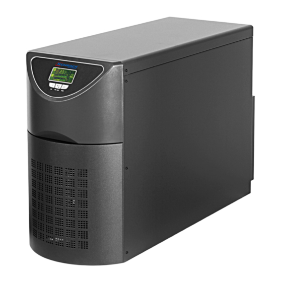
  • Seite 72: Ansichten Der Usv

    All manuals and user guides at all-guides.com ARSTELLUNG NSICHTEN DER Display Vorderansicht Erweiterungs-Steckplatz für zusätzliche Schnittstellen-Karten COMUNICATION SLOT Hauptschalter Remote emergency power off (R.E.P.O.) Kühlgebläse Kühlgebläse USB-Anschluss Buchsen IEC 10 A Power share Schnittstelle RS232 Sicherung Power share Schalter Schalter manueller Eingang und Ausgang Bypass Batterie-Sicherung...
  • Seite 73: Ansicht Display -Maske

    All manuals and user guides at all-guides.com ARSTELLUNG NSICHT DISPLAY ASKE Taste “SEL / SET” Taste “ON” Taste “STBY” Normalbetrieb Konfigurations-Bereich Netzbetrieb Anforderung Wartung Batteriebetrieb Timer Last-Stromversorgung über By-Pass Bereich Messwert-Anzeige Anzeige Batterie-Autonomie Stand-By / Alarm Anzeige Ladezustand...
  • Seite 74: Installation

    All manuals and user guides at all-guides.com NSTALLATION Ö FFNEN DER ERPACKUNG UND ONTROLLE DES NHALTS Nach dem Öffnen der Verpackung muss als erstes der Inhalt geprüft werden. Die Verpackung muss folgendes enthalten: Serielles Kabel RS232 2 Sicherungen für Batterie - 14x51 mm, 50A, Bedienungsanleitung + CD-ROM Software 400V Überbrückung (nur in den Versionen drei-...
  • Seite 75: Installationsmodalität

    All manuals and user guides at all-guides.com NSTALLATION WICHTIG: diese unterbrechungsfreie Stromversorgungseinheit ist ein Produkt, das die geltenden Vorschriften für elektromagnetische Verträglichkeit einhält (Kategorie C2). In einer Haushaltsumgebung kann es Radiointerferenzen verursachen. Der Benutzer könnte zusätzliche Vorkehrungen treffen müssen. Das Unternehmen haftet nicht für Schäden, die durch falsche Anschlüsse oder nicht in der Bedienungsanleitung beschriebene Arbeiten entstehen.
  • Seite 76: Bedienung

    All manuals and user guides at all-guides.com EDIENUNG NSCHLÜSSE DIE INSTALLATION MUSS AUSSCHLIESSLICH VON FACHPERSONAL VORGENOMMEN WERDEN. ALS ERSTES MUSS DER SCHUTZLEITER (ERDLEITER) AN DIE MIT GEKENNZEICHNETE KLEMME ANGESCHLOSSEN WERDEN. DIE USV DARF NICHT OHNE ERDUNG BETRIEBEN WERDEN. Hinweis: Werden die Angaben zu Nullleiter (N) und Phase (F) an den Steckdosen und Steckern beachtet, verändert der Einbau einer USV in eine bestehende Anlage den bestehenden Nullleiterbetrieb nicht.
  • Seite 77: Version Einphasig

    All manuals and user guides at all-guides.com EDIENUNG ERSION EINPHASIG 1. (EINPHASIGER ANSCHLUSS 5-6kVA): 3 Kabel mit Querschnitt 6 mm (ERDE, N und L) am Eingang, und 3 Kabel mit Querschnitt 6 mm für den Ausgang (ERDE, N und L) verwenden. 2.
  • Seite 78: Version Dreiphasig

    All manuals and user guides at all-guides.com EDIENUNG ERSION REIPHASIG Einphasiger Anschluss 1. (EINPHASIGER ANSCHLUSS 8-10kVA): 3 Kabel mit Querschnitt 10 mm2 (ERDE, N und L) am Eingang, und 3 Kabel mit Querschnitt 10 mm2 für den Ausgang (ERDE, N und L) verwenden. (EINPHASIGER ANSCHLUSS 6,5kVA): 3 Kabel mit Querschnitt 6 mm (ERDE, N und L) am Eingang, und 3 Kabel mit Querschnitt 6 mm...
  • Seite 79: Dreiphasiger Anschluss

    All manuals and user guides at all-guides.com EDIENUNG Dreiphasiger Anschluss 1. (DREIPHASIGER ANSCHLUSS 8-10kVA): 3 Kabel mit Querschnitt 6 mm2 (ERDE, L2 und L3) und 2 Kabel mit Querschnitt 10 mm2 (N, L1) am Eingang verwenden (Anmerkung: L1 und L2 haben einen größeren Querschnitt, weil sie im By-Pass-Betrieb den gesamten Eingangsstrom leiten).
  • Seite 80: Version Mit Externer By-Pass Fernsteuerung

    All manuals and user guides at all-guides.com EDIENUNG Version mit externer By-Pass Fernsteuerung Soll der Wartungs-By-Pass extern ferngesteuert werden, zuerst die oben angeführten Punkte 1, 2 und 3 ausführen. Anschließend wie folgt vorgehen: 1. Die oben beschriebenen Anweisungen für den Anschluss, 11 12 13 sowie für die Kabel-Anzahl und Querschnitt für die Leistungsanschlüsse befolgen.
  • Seite 81: Erstmaliges Einschalten

    All manuals and user guides at all-guides.com EDIENUNG RSTMALIGES INSCHALTEN 1) Sicherstellen, dass alle im vorstehenden Abschnitt "Anschlüsse" beschriebenen Arbeiten richtig ausgeführt worden sind. 2) Den der USV vorgeschalteten magnetothermischen Schalter schließen. 3) Die Schalter am Eingang und am Ausgang schließen, die Batterie-Sicherungen an der Rückseite der USV-Klemmen-Schutzabdeckung einsetzen.
  • Seite 82: Anzeigen Am Display

    All manuals and user guides at all-guides.com EDIENUNG NZEIGEN AM ISPLAY In diesem Kapitel werden ausführlich alle Informationen beschrieben, die am LCD-Display angezeigt werden können. Für ein besseres Verständnis können wir die angezeigten Informationen in drei Hauptgruppen unterteilen: Anzeigen des USV-Status Bereich Messwert-Anzeige Konfigurations-Bereich Anzeigen des USV-Status...
  • Seite 83: Bereich Messwert-Anzeige

    All manuals and user guides at all-guides.com EDIENUNG Bereich Messwert-Anzeige Am Display können nacheinander die wichtigsten USV-Messwerte angezeigt werden. Beim Einschalten der USV wird der Wert für die Netzspannung angezeigt. Um auf eine andere Anzeige umzuschalten, die Taste "SEL / SET" mehrfach drücken, bis der gewünschte Messwert angezeigt wird.
  • Seite 84: Dreiphasiger Anschluss

    All manuals and user guides at all-guides.com EDIENUNG Dreiphasiger Anschluss Nachstehend finden Sie einige Beispiele: GRAFISCHES BEISPIEL GRAFISCHES BEISPIEL BESCHREIBUNG BESCHREIBUNG Prozentwert Batterieladung Spannung Phase 1 Gesamt-Batteriespannung Prozentwert der angelegten Last. Spannung Phase 2 Stromaufnahme durch Last Temperatur des Spannung Phase 3 Elektronik-Kühlsystems in der USV Störung / Alarm...
  • Seite 85: Konfigurations-Bereich

    All manuals and user guides at all-guides.com EDIENUNG Konfigurations-Bereich Im Konfigurationsbereich sind die wichtigsten Betriebsparameter der USV zusammengefasst und es wird der Ist-Status angezeigt. Die in diesem Bereich enthaltenen Parameter können direkt über das Display geändert werden. EINSTELLBARE PARAMETER: Frequenz: Frequenz der Ausgangsspannung Frequenz Spannung: Ausgangsspannung Spannung...
  • Seite 86: Betriebsmodus

    All manuals and user guides at all-guides.com EDIENUNG ETRIEBSMODUS Der Betriebsmodus, der den Lasten den größten Schutz bietet, ist der Modus ON LINE (Default/ Voreinstellung), bei dem der Strom für die Last doppelt umgewandelt wird und am Ausgang so wieder hergestellt wird, dass er perfekt sinusförmig ist und Frequenz und Spannung unabhängig vom Eingang durch die präzise Steuerung des Mikroprozessors festgelegt werden (V.F.I.).
  • Seite 87: Usv-Konfiguration

    All manuals and user guides at all-guides.com EDIENUNG USV-K ONFIGURATION In den nachstehenden Tabelle sind alle Konfigurationsmöglichkeiten aufgeführt, die dem Anwender zur Verfügung stehen, um die USV optimal an seine Bedürfnisse anzupassen. ZEICHENERKLÄRUNG: Zeigt an, dass die Konfiguration außer über die Konfigurations-Software auch über das Display geändert werden kann.
  • Seite 88: Erweiterte Funktionen

    All manuals and user guides at all-guides.com EDIENUNG FUNKTION BESCHREIBUNG STANDARD MÖGLICHE KONFIGURATIONEN MODUS • Ausgeschaltet Alarmschwelle Kundeneinstellung für Ausgeschaltet • 0 ÷ 103 in Schritten von 1% für Höchstlast Überlast-Grenzwert Auswahl der Helligkeit des Helligkeitsstufe für Maximal Minimal ÷ Maximal in 20 Schritten LCD-Display das LCD-Display •...
  • Seite 89: Computer -Schnittstellen

    All manuals and user guides at all-guides.com EDIENUNG OMPUTER CHNITTSTELLEN Auf der Rückseite der USV (siehe Ansichten USV) befinden sich folgende Computer-Schnittstellen: Serielle Schnittstelle, erhältlich Anschluss RS232 USB-Anschluss. ANMERKUNG: Bei Verwendung eines Anschlusses wird der andere automatisch ausgeschaltet. Erweiterungs-Steckplatz für zusätzliche Schnittstellen-Karten COMMUNICATION SLOT. Anschlüsse RS232 und USB ANSCHLUSS RS232 USB-ANSCHLUSS...
  • Seite 90: Software

    All manuals and user guides at all-guides.com EDIENUNG OFTWARE Überwachungs- und Steuer-Software Die Software NetworkMonitor3 garantiert eine einfache und leicht verständliche Steuerung der USV mit Anzeige aller wichtigen Informationen, wie Eingangsspannung, angelegte Last, Batterie-Leistung. Außerdem kann sie automatisch Arbeitsschritte, wie programmiertes Runterfahren des Betriebssystems, Versenden von Email, SMS und Nachrichten im Netzwerk bei Auftreten besonderer, vom Anwender ausgewählten, Ereignisse vornehmen.
  • Seite 91: Problembehebung

    All manuals and user guides at all-guides.com ROBLEMBEHEBUNG Ein unregelmäßiger Betrieb der USV ist in vielen Fällen kein Anzeichen eines Defekts, sondern durch banale Probleme, Pannen oder Zerstreutheit verursacht. Wir empfehlen daher aufmerksam die nachstehende Tabelle zu lesen, in der für die Problembehebung nützliche Informationen zusammengefasst sind.
  • Seite 92: Aktiviert

    All manuals and user guides at all-guides.com ROBLEMBEHEBUNG PROBLEM MÖGLICHE URSACHE BEHEBUNG DER SUMMER ERTÖNT STÄNDIG UND AM Die Lasten auf einen Schwellenwert von 100% DIE AN DER USV DISPLAY WIRD EINER DER begrenzen (oder auf Anwender-Schwellenwert bei Code ANGELEGTE LAST IST ZU FOLGENDEN CODE GROSS A54).
  • Seite 93: Alarmcode

    All manuals and user guides at all-guides.com ROBLEMBEHEBUNG LARMCODE Durch die Verwendung eines hochentwickelten Autodiagnosesystems ist die USV in der Lage am Display eventuelle Anomalien/ Störungen anzuzeigen, die während des Normalbetrieb des Gerätes auftreten können. Besteht ein Problem, zeigt die USV am Display einen Code und den aktiven Alarmtyp (FAULT bzw. LOCK) an.
  • Seite 94 All manuals and user guides at all-guides.com ROBLEMBEHEBUNG 3. Aktive Steuerungen: Zeigt an, dass eine Fernsteuerung aktiv ist. CODE BESCHREIBUNG Fernsteuerungen zum Abschalten Fernsteuerungen Lasten auf By-Pass Fernsteuerungen zum Einschalten Batterie-Test läuft LOCK Die Anzeigen des Typs LOCK (Schutzabschaltung) haben normalerweise vorher eine Alarmanzeige. Wegen ihrer Bedeutung führen sie zum Abschalten des Wechselrichters und der Lasten-Stromversorgung über den By-Pass (dieses Verfahren gilt nicht für Schutzabschaltungen wegen starker und länger anhaltender Überlast sowie für Schutzabschaltungen wegen Kurzschluss).
  • Seite 95: Tabelle Technische Daten

    All manuals and user guides at all-guides.com ABELLE TECHNISCHE ATEN ABELLE TECHNISCHE ATEN MODELLE 5000VA 6000VA EINGANG (1 Ø + N Phasenspannungen) Nennspannung 220 – 230 – 240 Vac einphasig Zulässiger Bereich 0 - 280 Vac Spannungsbereich für Nichteinschaltung der...
  • Seite 96 All manuals and user guides at all-guides.com ABELLE TECHNISCHE ATEN MODELLE 6500VA 8000VA 10000VA EINGANG (3 Ø + N Phasenspannungen) Nennspannung 220 – 230 – 240 Vac einphasig / 380 – 400 – 415 Vac dreiphasig mit Nullleiter Zulässiger Bereich 0 - 280 Vac Spannungsbereich für Nichteinschaltung der Maximale Spannung 276Vac...
  • Seite 97: Tabelle Überlastzeiten

    All manuals and user guides at all-guides.com ABELLE TECHNISCHE ATEN Ü ABELLE BERLASTZEITEN BETRIEB ÜBER ÜBERLASTZEITEN BYPASS WECHSELRICHTER Schaltet den By-Pass nach 2 Sek. ein 100% < Last ≤ 125% Schutzabschaltung nach 60 Sek. Schutzabschaltung nach 120 Sek. Schaltet den By-Pass nach 2 Sek. ein 125% <...
  • Seite 98 All manuals and user guides at all-guides.com...
  • Seite 99 All manuals and user guides at all-guides.com MANUEL DE L’UTILISATEUR...
  • Seite 100 All manuals and user guides at all-guides.com NTRODUCTION Nous vous remercions d’avoir choisi l’un de nos produits. Notre entreprise est spécialisée dans le développement et la production de systèmes d’alimentation sans interruption. Les onduleurs de cette série sont des produits de haute qualité, attentivement conçus et construits en vue de garantir les meilleures performances.
  • Seite 101 All manuals and user guides at all-guides.com OMMAIRE RESENTATION UES ONDULEUR UE CACHE AFFICHEUR NSTALLATION ’ UVERTURE DE L EMBALLAGE ET VERIFICATION DE SON CONTENU ’ ODALITES D INSTALLATION ACCORDEMENTS ERSION MONOPHASEE ERSION TRIPHASE Raccordement monophasé Raccordement triphasé Version avec commande de by-pass externe distant REMIERE MISE EN MARCHE ISE EN MARCHE SUR RESEAU ISE EN MARCHE SUR BATTERIE...
  • Seite 102 All manuals and user guides at all-guides.com...
  • Seite 103: Presentation

    All manuals and user guides at all-guides.com RESENTATION Les onduleurs de la nouvelle série 5 - 6 monophasés et 6,5 - 8 - 10 kVA triphasés ont été conçus en utilisant l'état de l'art de la technologie actuellement disponible, de manière à garantir à l’utilisateur des performances maximales.
  • Seite 104: Vues Onduleur

    All manuals and user guides at all-guides.com RESENTATION UES ONDULEUR Afficheur Vue de face Slot d’extension Interrupteur COMUNICATION SLOT général Remote emergency power off (R.E.P.O.) Ventilateur de Ventilateur de redroidissement redroidissement Prises IEC 10 A Port de communication USB Power share Port de communication RS232 Fusible Power share...
  • Seite 105: Vue Cache Afficheur

    All manuals and user guides at all-guides.com RÉSENTATION UE CACHE AFFICHEUR Bouton “SEL / SET” Bouton “ON” Bouton “STBY” Fonctionnement normal Champ de configuration Fonctionnement sur réseau Demande de maintenance Fonctionnement sur batterie Timer Charge alimentée par by-pass Champ d’affichage mesures Indicateur d’autonomie batterie Stand-by / alarme Indicateur du niveau de charge...
  • Seite 106: Installation

    All manuals and user guides at all-guides.com NSTALLATION ’ UVERTURE DE L EMBALLAGE ET VERIFICATION DE SON CONTENU Après avoir ouvert l’emballage, commencer par vérifier son contenu. L’emballage doit contenir: Onduleur Câble série RS232 2 Fusibles pour batteries - 14x51 mm, 50A, Manuel utilisateur + CD-ROM logiciel 400V Shunt (seulement dans les versions tri-...
  • Seite 107: Modalites Dinstallation

    All manuals and user guides at all-guides.com NSTALLATION ATTENTION: cet onduleur est un produit conforme aux normes en vigueur en matière de compatibilité électromagnétique (classe C2). En milieu domestique il peut provoquer des interférences radio. L’utilisateur pourrait être contraint d’adopter des mesures supplémentaires. L’Entreprise décline toute responsabilité...
  • Seite 108: Raccordements

    All manuals and user guides at all-guides.com NSTALLATION ACCORDEMENTS L’INSTALLATION DOIT ETRE EXECUTEE EXCLUSIVEMENT PAR UN PERSONNEL QUALIFIE. LE PREMIER RACCORDEMENT A EFFECTUER EST CELUI DU CONDUCTEUR DE PROTECTION (CABLE DE PROTECTION) QUI DOIT ETRE BRANCHE A LA BORNE REPORTANT LE SYMBOLE L’ONDULEUR NE DOIT JAMAIS FONCTIONNER SANS RACCORDEMENT A L’INSTALLATION DE TERRE.
  • Seite 109: Version Monophasee

    All manuals and user guides at all-guides.com TILISATION ERSION MONOPHASEE 1. (RACCORDEMENT MONOPHASE 5-6kVA): utiliser 3 câbles ayant une section de 6 mm (TERRE, N et L) en entrée, et 3 câbles ayant une section de 6 mm en sortie (TERRE, N et L). 2.
  • Seite 110: Version Triphase

    All manuals and user guides at all-guides.com TILISATION ERSION TRIPHASE Raccordement monophasé 1. (RACCORDEMENT MONOPHASE 8-10kVA): utiliser 3 câbles ayant une section de 10 mm (TERRE, N et L) en entrée, et 3 câbles ayant une section de 10 mm en sortie (TERRE, N et L).
  • Seite 111: Raccordement Triphasé

    All manuals and user guides at all-guides.com TILISATION Raccordement triphasé 1. (RACCORDEMENT TRIPHASE 8-10kVA): Utiliser 3 câbles ayant une section de 6 mm2 (TERRE, L2 et L3) et 2 ayant une section de 10 mm2 (N, L1) en entrée (N.B.: L1 et N ont une section supérieure car en fonctionnement sur by-pass ils doivent supporter tout le courant d’entrée).
  • Seite 112: Version Avec Commande De By-Pass Externe Distant

    All manuals and user guides at all-guides.com TILISATION Version avec commande de by-pass externe distant Si l’on souhaite séparer la commande de by-pass de maintenance distant, suivre les indications des points 1, 2 et 3 précédents puis procéder comme suit: 11 12 13 1.
  • Seite 113: Premiere Mise En Marche

    All manuals and user guides at all-guides.com TILISATION REMIERE MISE EN MARCHE 1) S’assurer que toutes les opérations décrites au paragraphe précédent “Raccordements” ont été exécutées correctement. 2) Fermer le disjoncteur magnétothermique situé en amont de l’onduleur. 3) Fermer les interrupteurs d’entrée, de sortie et brancher les fusibles de batterie placés à l’arrière du boîtier de connexion de l’onduleur.
  • Seite 114: Indications Panneau Afficheur

    All manuals and user guides at all-guides.com TILISATION NDICATIONS PANNEAU AFFICHEUR Ce chapitre décrit de manière détaillée toutes les informations pouvant être visualisées sur l’afficheur LCD. Pour plus de clarté, les informations affichées peuvent être divisées en trois groupes principaux : Indicateurs d’état de l’onduleur Champ d’affichage des mesures Champ de configuration...
  • Seite 115: Champ D'affichage Des Mesures

    All manuals and user guides at all-guides.com TILISATION Champ d’affichage des mesures L’afficheur permet de visualiser en séquence les mesures les plus importantes relatives à l’onduleur. Au moment de la mise en marche de l’onduleur, l’afficheur visualise la valeur de la tension de réseau. Pour passer à...
  • Seite 116: Raccordement Triphasé

    All manuals and user guides at all-guides.com TILISATION Raccordement triphasé Quelques exemples sont reportés ci-après: EXEMPLE GRAPHIQUE EXEMPLE GRAPHIQUE DESCRIPTION DESCRIPTION Pourcentage de charge des batteries Tension phase 1 Tension totale des batteries Pourcentage de la charge appliquée Tension phase 2 Courant absorbé...
  • Seite 117: Champ De Configuration

    All manuals and user guides at all-guides.com TILISATION Champ de configuration Le champ de configuration regroupe les principaux paramètres de fonctionnement de l’onduleur et affiche leur état actuel. Les paramètres contenus dans ce champ peuvent être directement modifiés à partir du panneau afficheur.
  • Seite 118: Mode De Fonctionnement

    All manuals and user guides at all-guides.com TILISATION ODE DE FONCTIONNEMENT Le mode qui garantit le maximum de protection à la charge est le mode ON LINE (défaut) où l’énergie pour la charge subit une double conversion et où elle est reconstruite en sortie de manière parfaitement sinusoïdale avec une fréquence et une tension fixées par le contrôle numérique par microprocesseur indépendamment de l’entrée (V.F.I.).
  • Seite 119: Configuration De L ' Onduleur

    All manuals and user guides at all-guides.com TILISATION ’ ONFIGURATION DE L ONDULEUR Le tableau suivant illustre toutes les configurations possibles dont dispose l’utilisateur pour adapter au mieux l’onduleur à ses exigences. LEGENDE: Indique que la configuration peut être modifiée non seulement à travers le logiciel de configuration fourni mais aussi depuis le panneau afficheur.
  • Seite 120: Fonctions Avancees

    All manuals and user guides at all-guides.com TILISATION FONCTION DESCRIPTION PREDEFINI CONFIGURATIONS POSSIBLES MODE Seuil d’alarme • Désactivé Sélectionne la limite pour charge Désactivé de surcharge • 0 ÷ 103 par palier d’1% maximum Sélectionne le niveau Luminosité de luminosité de Maximum Minimum ÷...
  • Seite 121: Ports De Communication

    All manuals and user guides at all-guides.com TILISATION ORTS DE COMMUNICATION La partie arrière de l’onduleur (voir Vues onduleur) présente les ports de communication suivants: Port série, disponible avec connecteur RS232 et connecteur USB. NOTE: l’utilisation d’un connecteur exclut automatiquement l’autre. Slot d’extension pour cartes d’interface supplémentaires COMMUNICATION SLOT Connecteurs RS232 et USB CONNECTEUR RS232...
  • Seite 122: Logiciels

    All manuals and user guides at all-guides.com TILISATION OGICIELS Logiciel de surveillance et de contrôle Le logiciel NetworkMonitor3 garantit une gestion efficace et intuitive de l’onduleur. En effet, il permet de visualiser toutes les informations les plus importantes telles que la tension d’entrée, la charge appliquée et la capacité...
  • Seite 123: Resolution Des Problemes

    All manuals and user guides at all-guides.com ESOLUTION DES PROBLEMES Un mauvais fonctionnement de l’onduleur n’est pas forcément signe d’une panne mais il est souvent dû à des problèmes simples, à des inconvénients ou à des négligences. Par conséquent il est conseillé de consulter attentivement le tableau reporté ci-dessous qui résume les informations utiles pour la résolution des problèmes les plus communs.
  • Seite 124: Résolution Des Problèmes

    All manuals and user guides at all-guides.com ÉSOLUTION DES PROBLÈMES PROBLÈME CAUSE POSSIBLE SOLUTION LE BUZZER SONNE EN CONTINU ET LA CHARGE APPLIQUÉE À Réduire la charge jusqu’au seuil de 100% ( ou seuil L’AFFICHEUR SIGNALE L’ONDULEUR EST TROP L’UN DES CODES d’utilisation en cas de code A54).
  • Seite 125: Codes Dalarme

    All manuals and user guides at all-guides.com ÉSOLUTION DES PROBLÈMES ’ ODES D ALARME A travers un système d’autodiagnostic sophistiqué, l’onduleur est en mesure de vérifier et de signaler sur le panneau afficheur les anomalies et/ou pannes éventuelles susceptibles de se produire pendant le fonctionnement normal de l’appareil.
  • Seite 126 All manuals and user guides at all-guides.com ÉSOLUTION DES PROBLÈMES 3. Commandes actives: Indique la présence d’une commande distante active. CODE DESCRIPTION Commande distante d’arrêt Commande distante de charge sur by-pass Commande distante de mise en marche Test batterie en exécution LOCK Les signalisations de type LOCK (arrêt total) sont généralement précédées d’un signal d’alarme et, en raison de leur envergure, elles comportent l’arrêt de l’onduleur et l’alimentation de la charge à...
  • Seite 127: Tableau Donnees Techniques

    All manuals and user guides at all-guides.com ABLEAU DONNEES TECHNIQUES ABLEAU DES DONNEES TECHNIQUES ONDULEUR MODELES 5000VA 6000VA ENTREE (1 Ø + N tensions étoilées) Tension nominale 220 – 230 – 240 Vca monophasée Plage acceptée 0 - 280 Vca...
  • Seite 128 All manuals and user guides at all-guides.com ABLEAU DONNÉES TECHNIQUES MODÈLES 6500VA 8000VA 10000VA ENTRÉE (3 Ø + N tensions étoilées) Tension nominale 220 – 230 – 240 Vca monophasée / 380 – 400 – 415 Vca triphasée avec neutre Plage acceptée 0 - 280 Vca Plage de tension pour non-intervention batterie...
  • Seite 129: Tableau Des Temps De Surcharge

    All manuals and user guides at all-guides.com ABLEAU DONNÉES TECHNIQUES ABLEAU DES TEMPS DE SURCHARGE FONCTIONNEMENT SUR TEMPS DE SURCHARGE BY-PASS ONDULEUR Activation by-pass au bout de 2 s. 100% < Charge ≤ 125% Arrêt total au bout de 60 s. arrêt total au bout de 120 s.
  • Seite 130 All manuals and user guides at all-guides.com...
  • Seite 131 All manuals and user guides at all-guides.com MANUAL DE USO...
  • Seite 132 All manuals and user guides at all-guides.com NTRODUCCIÓN Le agradecemos que haya elegido nuestro producto. Nuestra empresa es especialista en el diseño y producción de sistemas de alimentación ininterrumpida (SAI). Los SAI de esta serie son productos de alta calidad, diseñados cuidadosamente y construidos con la finalidad de garantizar las mejores prestaciones.
  • Seite 133 All manuals and user guides at all-guides.com ÍNDICE RESENTACIÓN VISTAS VISTA DE LA PANTALLA NSTALACIÓN PERTURA DEL EMBALAJE Y COMPROBACIÓN DE SU CONTENIDO ODO DE INSTALACIÓN ONEXIONES ERSIÓN MONOFÁSICA ERSIÓN TRIFÁSICA Conexión monofásica Conexión trifásica Versión con comando de bypass remoto externo PRIMER ENCENDIDO NCENDIDO CON LA RED NCENDIDO CON LA BATERÍA...
  • Seite 134 All manuals and user guides at all-guides.com...
  • Seite 135: Presentación

    All manuals and user guides at all-guides.com RESENTACIÓN Con el objetivo de proporcionar al usuario las máximas prestaciones, la nueva serie de los SAI, de 5 - 6 kVA monofásicos y de 6,5 - 8 - 10 kVA trifásicos, se ha diseñando utilizando los últimos avances tecnológicos disponibles en la actualidad.
  • Seite 136: Vistas Sai

    All manuals and user guides at all-guides.com RESENTACIÓN VISTAS Pantalla Vista frontal Ranura de expansión Interruptor general REPO (Interruptor de apagado remoto de emergencia) Ventilador de refrigeración Ventilador de refrigeración Toma CEI 10 A Puerto de comunicación USB Powershare Puerto de comunicación RS232 Fusible Poweshare Interruptores de...
  • Seite 137: Vista De La Pantalla

    All manuals and user guides at all-guides.com RESENTACIÓN VISTA DE LA PANTALLA Botón “SEL / SET” Botón “ON” Botón “STBY” Funcionamiento normal Área de configuración Funcionamiento con la red Solicitud de mantenimiento Funcionamiento con la batería Temporizador Carga alimentada por bypass Área de visualización de mediciones Indicador de autonomía de la batería Stand-by / Alarma...
  • Seite 138: Instalación

    All manuals and user guides at all-guides.com NSTALACIÓN PERTURA DEL EMBALAJE Y COMPROBACIÓN DE SU CONTENIDO Tras la apertura del embalaje, es aconsejable comprobar en primer lugar su contenido. Éste deberá estar formado por: Cable serial RS232 2 fusibles por batería - 14x51 mm, 50 A, Manual del usuario + CD-ROM con software 400 V Rampa...
  • Seite 139: Modo De Instalación

    All manuals and user guides at all-guides.com NSTALACIÓN NOTA IMPORTANTE: este sistema de alimentación ininterrumpida (SAI) es un producto que respeta las normativas vigentes sobre compatibilidad electromagnética (categoría C2). En ambiente doméstico puede provocar interferencias radio. El usuario podría adoptar medidas suplementarias. La Empresa no asume la responsabilidad por daños provocados por conexiones incorrectas o por operaciones no descritas en este manual.
  • Seite 140: Conexiones

    All manuals and user guides at all-guides.com NSTALACIÓN ONEXIONES LA INSTALACIÓN SOLO PODRÁ SER REALIZADA POR PERSONAL CUALIFICADO. LA PRIMERA CONEXIÓN QUE SE DEBE REALIZAR ES LA DEL CONDUCTOR DE PROTECCIÓN (CABLE DE TIERRA), QUE SE INTRODUCIRÁ EN EL BORNE CON EL SÍMBOLO EL SAI NO DEBE ESTAR EN FUNCIONAMIENTO SIN CONECTARLO A LA TOMA DE TIERRA.
  • Seite 141: Versión Monofásica

    All manuals and user guides at all-guides.com ERSIÓN MONOFÁSICA 1. (CONEXIÓN MONOFÁSICA 5-6 kVA): se deben utilizar 3 cables con una sección de 6 mm (TIERRA, N y L) de entrada y 3 cables con una sección de 6 mm de salida (TIERRA, N y L).
  • Seite 142: Versión Trifásica

    All manuals and user guides at all-guides.com ERSIÓN TRIFÁSICA Conexión monofásica 1. (CONEXIÓN MONOFÁSICA 8-10 kVA): utilizar 3 cables con una sección de 10 mm (TIERRA, N y L) para la entrada y 3 cables con una sección de 10 mm para la salida (TIERRA, N y L).
  • Seite 143: Conexión Trifásica

    All manuals and user guides at all-guides.com Conexión trifásica 1. (CONEXIÓN TRIFÁSICA 8-10 kVA): Utilizar 3 cables con una sección de 6 mm2 (TIERRA, L2 y L3) y 2 con una sección de 10 mm2 (N, L1) para la entrada (nota: L1 y N poseen una sección mayor porque en el modo de funcionamiento con el bypass deben soportar toda la corriente de entrada).
  • Seite 144: Versión Con Comando De Bypass Remoto Externo

    All manuals and user guides at all-guides.com Versión con comando de bypass remoto externo Para sacar fuera el comando del bypass de mantenimiento remoto hay que seguir los puntos 1, 2 y 3 explicados anteriormente. Se deben realizar las siguientes operaciones: 11 12 13 1.
  • Seite 145: Primer Encendido

    All manuals and user guides at all-guides.com PRIMER ENCENDIDO Asegurarse de que todas las operaciones descritas en el párrafo anterior “Conexiones” se han llevado a cabo correctamente. Cerrar el interruptor magnetotérmico superior del SAI. Cerrar los interruptores de entrada, los de salida, e introducir fusibles de batería en la parte trasera de la tapa del SAI.
  • Seite 146: Indicaciones Del Panel De La Pantalla

    All manuals and user guides at all-guides.com NDICACIONES DEL PANEL DE LA PANTALLA En este capítulo se describe de forma detallada toda la información que puede aparecer en la pantalla LCD. Para una mejor comprensión, podemos subdividir la información visualizada en tres grupos principales: Indicadores del estado del SAI Área de visualización de mediciones Área de configuración...
  • Seite 147: Área Visualización Mediciones

    All manuals and user guides at all-guides.com Área visualización mediciones En la pantalla se pueden visualizar en secuencia las medidas más importantes relacionadas con el SAI. Con el encendido del SAI, en la pantalla se puede ver el valor de la tensión de red. Para pasar a una visualización diferente hay que presionar el botón “SEL / SET”...
  • Seite 148: Conexión Trifásica

    All manuals and user guides at all-guides.com Conexión trifásica A continuación se presentan algunos ejemplos: EJEMPLO GRÁFICO DESCRIPCIÓN EJEMPLO GRÁFICO DESCRIPCIÓN Porcentaje de carga de las baterías Tensión fase 1 Tensión total de las baterías Porcentaje de la carga aplicada Tensión fase 2 Corriente absorbida por la carga...
  • Seite 149: Área De Configuración

    All manuals and user guides at all-guides.com Área de configuración El área de configuración reagrupa los principales parámetros de funcionamiento del SAI y muestra su estado actual. Los parámetros contenidos en esta área se pueden modificar directamente en la pantalla. PARÁMETROS CONFIGURABLES: Frecuencia: Frecuencia de la tensión de salida Frecuencia...
  • Seite 150: Modos De Funcionamiento

    All manuals and user guides at all-guides.com ODOS DE FUNCIONAMIENTO El modo que garantiza la máxima protección a la carga es el modo ON LINE (predeterminado): en él la energía para la carga sufre una doble conversión y se reconstruye en la salida de una forma perfectamente sinusoidal, y la frecuencia y la tensión son fijadas por un control digital preciso con microprocesador de forma independiente de la entrada (V.F.I.).
  • Seite 151: Configuración Del Sai

    All manuals and user guides at all-guides.com ONFIGURACIÓN DEL El siguiente cuadro muestra todas las posibilidades que tiene el usuario de configurar el SAI para adaptarlo de la mejor forma a sus propias necesidades. LEYENDA: Indica que la configuración se puede modificar, además de a través del software de configuración, mediante el panel de la pantalla.
  • Seite 152: Funciones Avanzadas

    All manuals and user guides at all-guides.com FUNCIÓN DESCRIPCIÓN PREDEFINIDO POSIBLES CONFIGURACIONES MODOS Umbral de • Deshabilitado Selecciona el límite de alarma para Deshabilitado • usuario de sobrecarga 0 ÷ 103 en pasos de 1% carga máxima Selecciona el nivel de Luminosidad de luminosidad de la Máxima...
  • Seite 153: Puertos De Comunicación

    All manuals and user guides at all-guides.com UERTOS DE COMUNICACIÓN En la parte posterior del SAI (véase Vistas SAI) están presentes los siguientes puertos de comunicación: Puerto serial, disponible con conector RS232 y conector USB. ATENCIÓN: el empleo de un conector excluye automáticamente el otro. Ranura de expansión para tarjetas de interfaz auxiliares COMMUNICATION SLOT.
  • Seite 154: Software

    All manuals and user guides at all-guides.com OFTWARE Software de supervisión y control El software NetworkMonitor3 garantiza una gestión eficaz e intuitiva del SAI y muestra la información más relevante como la tensión de entrada, la carga conectada y la capacidad de las baterías. Además, puede ejecutar de forma automática operaciones de apagado, envío de correos electrónicos, SMS y mensajes de red cuando se producen situaciones específicas seleccionadas por el usuario.
  • Seite 155: Solución De Problemas

    All manuals and user guides at all-guides.com SOLUCIÓN DE PROBLEMAS A menudo un funcionamiento del SAI que no sea normal no indica una avería, sino que se debe únicamente a problemas menores, inconvenientes o distracciones. Por lo tanto, se aconseja consultar atentamente el siguiente cuadro que recoge información útil para la resolución de los problemas más frecuentes.
  • Seite 156 All manuals and user guides at all-guides.com SOLUCIÓN DE PROBLEMAS PROBLEMA CAUSA POSIBLE SOLUCIÓN EL ZUMBADOR SUENA DE FORMA CONTINUADA Y LA CARGA QUE SE APLICA Reduzca la carga hasta el umbral del 100% (o umbral de LA PANTALLA INDICA AL SAI ES DEMASIADO UNO DE LOS SIGUIENTES usuario en el caso del código A54).
  • Seite 157: Códigos De Alarma

    All manuals and user guides at all-guides.com SOLUCIÓN DE PROBLEMAS ÓDIGOS DE ALARMA Gracias a un sofisticado sistema de autodiagnóstico, el SAI es capaz de comprobar e indicar en la pantalla las posibles anomalías y/o averías que se pudieran producir durante su funcionamiento normal. Cuando hay un problema, el SAI lo indica mostrando en la pantalla el código y el tipo de alarma que está...
  • Seite 158 All manuals and user guides at all-guides.com SOLUCIÓN DE PROBLEMAS Comandos activos: señala la presencia de un comando remoto activado. CÓDIGO DESCRIPCIÓN Comando remoto de apagado Comando remoto de carga en el bypass Comando remoto de encendido Realizando la prueba de baterías LOCK Las señalizaciones de tipo LOCK (bloqueo) normalmente van precedidas de una señal de alarma y, por su importancia, implican el apagado del inversor y la alimentación de la carga a través de la línea de bypass (se...
  • Seite 159: Cuadro De Datos Técnicos

    All manuals and user guides at all-guides.com UADRO DE DATOS TÉCNICOS UADRO DE DATOS TÉCNICOS MODELOS 5000 VA 6000 VA ENTRADA (1 Ø + N tensiones estrelladas) Tensión nominal 220 – 230 – 240 Vac monofásico Rango aceptado 0 - 280 Vac Rango de tensión para la no intervención de la Tensión máxima 276 Vac batería...
  • Seite 160 All manuals and user guides at all-guides.com UADRO DE DATOS TÉCNICOS MODELOS 6500VA 8000VA 10000VA ENTRADA (3 Ø + N tensiones estrelladas) Tensión nominal 220 – 230 – 240 Vac monofásico / 380 – 400 – 415 Vac trifásica con neutro Rango aceptado 0 - 280 Vac Rango de tensión para que no entre en...
  • Seite 161: Cuadro De Tiempos De Sobrecarga

    All manuals and user guides at all-guides.com UADRO DE DATOS TÉCNICOS UADRO DE TIEMPOS DE SOBRECARGA FUNCIONAMIENTO CON TIEMPOS DE SOBRECARGA BYPASS INVERSOR Activa bypass a los 2 s 100% < Carga ≤ 125% Bloqueo después de 60 s Bloqueo después de 120 s Activa bypass a los 2 s 125% <...
  • Seite 162 All manuals and user guides at all-guides.com...
  • Seite 163 All manuals and user guides at all-guides.com...
  • Seite 164 All manuals and user guides at all-guides.com 0MNUTM4NPB...

Diese Anleitung auch für:

6000va6500va8000va10000va

Inhaltsverzeichnis