KRAUSE ProTec Aufbau- Und Verwendungsanleitung
Fahrgeruest
Vorschau ausblenden
Andere Handbücher für ProTec:
- Aufbau- und verwendungsanleitung (36 Seiten) ,
- Aufbau- und verwendungsanleitung (40 Seiten) ,
- Aufbau- und verwendungsanleitung (43 Seiten)

Verwandte Anleitungen für KRAUSE ProTec


Inhaltszusammenfassung für KRAUSE ProTec
- Seite 2 All manuals and user guides at all-guides.com EN 1004 3 8/12 XXXD • Fahrgerüst nach EN 1004 • Gerüstgruppe 3 EN 1004 3 8/12 XXXD • Mobile Scaffold according to EN 1004 • Scaffold Group 3 FahrGerüst ProTec Mobile scaffold ProTec...
-
Seite 3: Inhaltsverzeichnis
All manuals and user guides at all-guides.com Inhaltsverzeichnis 1. Allgemeines ..... . . 4 1.1 Verantwortungsbereich des Betreibers ..4 1.2 Hersteller . -
Seite 4: Allgemeines
All manuals and user guides at all-guides.com 1. Allgemeines Diese Anleitung beschreibt den Auf- und Abbau, sowie die Verwendung des mobilen Alu-Arbeitsgerüstes. In dieser Anleitung sind wichtige Sicherheitshinweise angegeben. Lesen Sie deshalb die Anleitung vor der Benutzung sorgfältig durch und machen Sie sich mit den Sicherheitsbestimmungen vertraut. -
Seite 5: Hersteller
(Richtlinien, Verordnungen, Gesetze etc.) für eine sichere Handhabung eingehalten werden. 1.2 Hersteller Hersteller des in der vorliegenden Dokumentation beschriebenen Arbeitsgerüstes ist die Firma: KRAUSE-Werk GmbH & Co. KG Am Kreuzweg 3 D 36304 Alsfeld Telefon: 06631 / 795-0 Telefax: 06631 / 795-139 www.krause-systems.com... -
Seite 6: Urheber- Und Schutzrechte
All manuals and user guides at all-guides.com – Bei der Verwendung von nicht Originalersatz- und/oder Zubehörteilen. – Bei der Verwendung von beschädigten oder fehlerhaften Bauteilen. – Eine Erhöhung der Arbeitshöhe durch Verwendung von Leitern, Kästen oder anderen Vorrichtungen. 1.5 Urheber - und Schutzrechte Alle Rechte an der Aufbau- und Verwendungsanleitung liegen beim Hersteller. -
Seite 7: Nicht Bestimmungsgemäßer Gebrauch
All manuals and user guides at all-guides.com Vor dem Gebrauch ist sicherzustellen, dass alle erforderlichen Sicherheitsvorkehrungen getroffen wurden und das Gerüst ordnungsgemäß entsprechend der Aufbau- und Ver- wendungsanleitung errichtet wurde. Das Gerüst ist gegebenenfalls mit Ballast oder mit Auslegern gegen Kippen zu sichern. 2.2 Nicht bestimmungsgemäßer Gebrauch Das Arbeitsgerüst darf nur für den unter 2.1 angegebenen bestimmungsgemäßen Gebrauch eingesetzt werden. -
Seite 8: Sicherheitsbestimmungen Beim Verfahren Des Gerüstes
All manuals and user guides at all-guides.com – Das Springen auf der Belagbühne ist verboten. – Das Hinauslehnen und Gegenstemmen ist verboten. – Ein Einsatz des Gerüstes ist nur bis zu einer Windstärke 6 (~ 45 km/h) zulässig. Vor Überschreitung der Windstärke 6 ist das Gerüst abzubauen oder in einen windgeschützten Bereich zu verfahren und dort gegen Kippen zu sichern. -
Seite 9: Verhalten Bei Arbeiten An Elektrischen
All manuals and user guides at all-guides.com 3.4 Verhalten bei Arbeiten an elektrischen Anlagen mit dem beschriebenen Gerüst Vor dem Arbeiten an elektrischen Anlagen mit einem FahrGerüst ist darauf zu achten, dass – die Anlage freigeschaltet ist – die Anlage gegen Wiedereinschalten gesichert ist –... -
Seite 10: Aufbau
All manuals and user guides at all-guides.com 4. Aufbau 4.1 Allgemeines Der Aufbau des Gerüstes darf erst erfolgen, wenn die Angaben zum Produkt (Abschnitt 2) und die Sicherheitsbestimmungen (Abschnitt 3) vollständig durchgelesen wurden. Für den Auf- und Abbau sind mindestens 2 Personen notwendig. Vor dem Aufbau ist sicherzustellen, dass alle für den Aufbau notwendigen Bauteile und Werkzeuge vorhanden sind und die Bauteile nicht beschädigt sind. - Seite 11 All manuals and user guides at all-guides.com SICHERHEITSHINWEIS Alle Geländer- und Alle Steckver- Diagonalstreben bindungen sowie Belagbühnen müssen mit Fall- müssen mit dem steckern ge- Sicherungsset sichert werden. gesichert werden Sicherungsset Sicherungsset Belagbühne Teile-Nr. 718914, M 5 x 65 mm Teile-Nr.
- Seite 12 All manuals and user guides at all-guides.com Kennzeichnung Das Typenschild ist an den Vertikalrahmen des ProTec FahrGerüst-Systems ® angebracht.
-
Seite 13: Bezeichnung Der Zubehörteile
All manuals and user guides at all-guides.com 4.2 Bezeichnung der Zubehörteile Basisstrebe Vertikalrahmen 1 m Geländerstrebe Diagonalstrebe Ausleger Ballastgewicht 10 kg Längsbord Fahrrolle ø 150 mm höhen- verstellbar Querbord Fußplatte Vertikalrahmen 2 m Fallstecker Fahrtraverse Belagbühne 8 mm... -
Seite 14: Aufbau Des Gerüstes
All manuals and user guides at all-guides.com 4.3 Aufbau des Gerüstes Schritt 1 Legen Sie sich 2 Fahrtraversen und 2 Basisstreben bereit, entfernen sie die Schloßschrauben und stecken Sie die Basisstreben mit der Öffnung über die Fahrtraversen. Achten Sie darauf, dass die Basisstreben einen Abstand von ca. - Seite 15 All manuals and user guides at all-guides.com Dann werden die Fahrrollen, wie gezeigt, in die Fahrtraversen einge- schoben und mittels Flügelschraube an diesen befestigt. ACHTUNG Stellen Sie die Fahrrollen in die hier gezeigte Stellung und betätigen Sie die Bremsen durch Niederdrücken der Bremshebel.
- Seite 16 All manuals and user guides at all-guides.com Schritt 3 Verschieben Sie die Basisstreben so, dass die Vertikalrahmen von oben aufgesteckt werden können und sichern Sie die Ver- bindungen mit Fallsteckern. Ziehen Sie die Muttern der Basisstreben fest an. Richten Sie im Anschluss das Gerüst sowohl über die Quer- als auch über die Längsseite mit einer Wasserwaage aus.
- Seite 17 All manuals and user guides at all-guides.com Schritt 4 Setzen Sie die Diagonalstrebe von der ersten Sprosse des einen zur fünften Sprosse der gegenüberliegenden Vertikalrahmens ein und befestigen Sie die Strebe mit den Sicherungssets. Nehmen Sie die zweite Diagonale und montieren Sie diese, wie im Bild gezeigt, entgegengesetzt diagonal von der ersten in die fünfte Sprosse und befestiegen Sie auch diese mit den...
- Seite 18 All manuals and user guides at all-guides.com Wichtig: Bevor Sie weiter Aufbauen, sollten Sie zuvor unbedingt das Gerüst mit den, je nach Aufbauhöhe, nötigen Ballastgewichten bestücken. Ballastierungsangaben finden Sie in dieser Aufbau- und Verwendungs- anleitung auf Seite 27 – 28. Schritt 6 Setzen Sie die weiteren Diagonalstre- ben ein.
- Seite 19 All manuals and user guides at all-guides.com Schritt 7 Schaffen Sie eine Hilfsebene aus stabilen Maurerbohlen und lassen Sie sich die Diagonalstreben anreichen. Hinweis: Während des Auf- und Abbaus sind Hilfs-ebenen vorzusehen. Die Hilfse- benen sind nach Abschluß des Auf- baus wieder zu entfernen.
- Seite 20 All manuals and user guides at all-guides.com Hängen Sie dann die Belagbühne mit den dafür vorgesehenen Öffnungen in die obersten Sprossen der Vertikalrah- men ein. Ziehen Sie nun die schon vormontierten Sicherungssets fest an. Schritt 9 Lassen Sie sich anschließend die 1 m Vertikalrahmen anreichen und hängen Sie diese, wie hier im Bild zu sehen, über die Rohrverbinder der 2 m...
- Seite 21 All manuals and user guides at all-guides.com Steigen Sie vorsichtig nach oben, es ist noch kein Seitenschutz vorhanden. Bauen Sie die oberen, 1 m Vertikal- rahmen ein und sichern Sie die Verbindungen mit den Fallsteckern. Schritt 10 Lassen Sie sich die Geländerstreben nach oben reichen um diese zu montieren und sie mit den Sicherung- sets zu befestigen.
- Seite 22 All manuals and user guides at all-guides.com Schritt 11 Lassen Sie sich die beiden Längs- und die beiden Querbords anreichen. Schritt 12 Montieren Sie zuerst die Querbords mit den Ausklinkungen nach oben (unteres linkes Bild), danach setzen sie die Längsbords innerhalb der Rahmen auf die Querbords (unteres rechtes Bild).
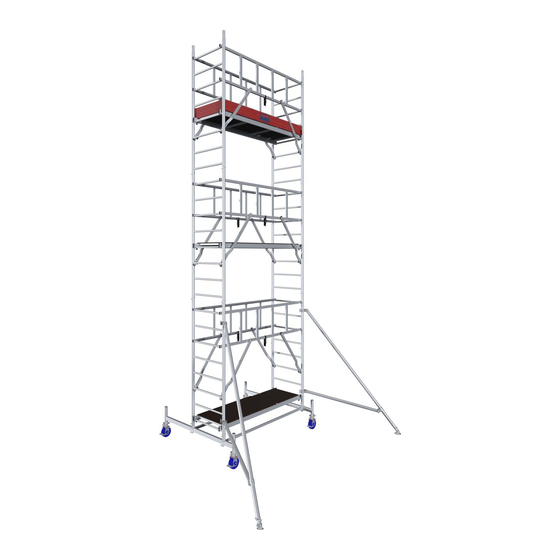
- Seite 23 All manuals and user guides at all-guides.com Die Abbildung zeigt das fertig montierte Gerüst mit einer Arbeitshöhe von 6,30 m.
-
Seite 24: Aufbauvarianten
All manuals and user guides at all-guides.com 4.4 Aufbauvarianten Aufbauvariante mit Auslegern Montieren Sie die Ausleger wie im nebenstehenden Bild gezeigt. Die Füße der Ausleger müssen immer fest auf dem Boden aufstehen, gegebenen- falls sind bruchsichere Unter- lagen zu verwenden. Die Befestigungskupplungen mit Halbschalen der Ausleger dienen der Verdrehsicherung und... -
Seite 25: Montage Des Stabilisierungs-Sets
All manuals and user guides at all-guides.com 4.5 Montage des Stabilisierungs-Sets Bei der Verwendung als Wandgerüst kann dies mit dem Stabilisierungs-Set bestückt und an der Wand befestigt werden. Dies dient lediglich der weiteren Stabilisierung des Gerüstes. Der Einsatz vom Stabilisierungs-Set ersetzt auf keinen Fall die vorgeschriebenen Ballastgewichte und Ausleger (siehe Seite 26 –... -
Seite 26: Ballastierung Des Gerüstes
All manuals and user guides at all-guides.com 4.6 Ballastierung des Gerüstes Freistehende Gerüste müssen mit Ballastgewichten an den Traversen beschwert werden, damit die Standsicherheit gewährleistet ist. Die Anzahl der Ballastgewichte ist von der Höhe des Gerüstes abhängig und kann aus den folgenden Tabellen entnommen werden (Seite 27 und 28). -
Seite 27: Ballastierung, Einsatz Im Geschlossenen Raum
All manuals and user guides at all-guides.com Ballastierung, Einsatz im geschlossenen Raum Stand- Gerüst mittig Gerüst einseitig Gerüst einseitig Gerüst mittig höhe auf Traverse auf Traverse auf Traverse auf Traverse in m mit 4 Auslegern mit 2 Auslegern 10,3 x = nicht möglich Diese Tabelle zeigt die Anzahl der Ballastgewichte auf der Fahrtraverse des Gerüstes. -
Seite 28: Ballastierung, Einsatz Im Freien
All manuals and user guides at all-guides.com Ballastierung, Einsatz im Freien Gerüst mittig Gerüst einseitig Stand- Gerüst einseitig Gerüst mittig höhe auf Traverse auf Traverse auf Traverse auf Traverse in m mit 4 Auslegern mit 2 Auslegern x = nicht möglich... -
Seite 29: Modellübersicht
All manuals and user guides at all-guides.com 5. Modellübersicht Achtung: In diesen schematischen Abbildungen sind keine Fallstecker und Ballastgewichte abgebildet. Baugruppen-Nr. Art.-Nr. Baugruppen-Nr. Art.-Nr. 2201 910110 2202 910097 Arbeitshöhe: Arbeitshöhe: 2,90 m 4,30 m Gerüsthöhe: 2,30 m Gerüsthöhe: 3,30 m Standhöhe Standhöhe 0,90 m... - Seite 30 All manuals and user guides at all-guides.com Baugruppen-Nr. Art.-Nr. Baugruppen-Nr. Art.-Nr. 2203 910134 2204 910141 Arbeitshöhe: Arbeitshöhe: 5,30 m 6,30 m Gerüsthöhe: 4,30 m Gerüsthöhe: 5,30 m Standhöhe Standhöhe 3,30 m 4,30 m...
- Seite 31 All manuals and user guides at all-guides.com Baugruppen-Nr. Art.-Nr. Baugruppen-Nr. Art.-Nr. 2205 910158 2206 910165 Arbeitshöhe: 7,30 m Arbeitshöhe: 8,30 m Gerüsthöhe: 6,30 m Gerüsthöhe: 7,30 m Standhöhe Standhöhe 5,30 m 6,30 m...
- Seite 32 All manuals and user guides at all-guides.com Baugruppen-Nr. Art.-Nr. Baugruppen-Nr. Art.-Nr. 2207 910172 2208 910189 Arbeitshöhe: Arbeitshöhe: 9,30 m 10,30 m Gerüsthöhe: 8,30 m Gerüsthöhe: 9,30 m Standhöhe Standhöhe 7,30 m 8,30 m...
- Seite 33 All manuals and user guides at all-guides.com Baugruppen-Nr. Art.-Nr. Baugruppen-Nr. Art.-Nr. 2209 910196 2210 910202 Arbeitshöhe: Arbeitshöhe: 11,30 m 12,30 m Gerüsthöhe: 10,30 m Gerüsthöhe: 11,30 m Standhöhe Standhöhe 9,30 m 10,30 m...
-
Seite 34: Technische Daten
All manuals and user guides at all-guides.com 6. Technische Daten Stückliste Alu-FahrGerüst Länge 2,00 m, Breite 0,70 m Artikel-Nr. 910110 910097 910134 910141 910158 Baugruppennummer 2201 2202 2203 2204 2205 Arbeitshöhe 2,90 m 4,30 m 5,30 m 6,30 m 7,30 m Gerüsthöhe 2,30 m 3,30 m... - Seite 35 All manuals and user guides at all-guides.com Stückliste Alu-FahrGerüst Fortsetzung Artikel-Nr. 910165 910172 910189 910196 910202 Baugruppennummer 2206 2207 2208 2209 2210 Arbeitshöhe 8,30 m 9,30 m 10,30 m 11,30 m 12,30 m Gerüsthöhe 7,30 m 8,30 m 9,30 m 10,30 m 11,30 m Standhöhe...
- Seite 36 All manuals and user guides at all-guides.com Paket Bestell-Nr. 910301 910318 910325 910332 910349 910356 910363 Artikel Gewicht Bezeichnung Stück Stück Stück Stück Stück Stück Stück in kg 915016 Vertikalrahmen 2 m 915023 Vertikalrahmen 1 m 911001 Belagbühne 912800 Diagonalstrebe 912206 Geländerstrebe 912848...
-
Seite 37: Abbau Des Gerüstes
All manuals and user guides at all-guides.com 7. Abbau des Gerüstes Alle Gerüste sind in umgekehrter Reihenfolge der jeweiligen Aufbaubeschreibung abzubauen. 8. Überprüfung, Pflege und Wartung Vor dem Aufbau sind alle Teile auf Beschädigung zu überprüfen und bei Beschädigung auszutauschen. Es dürfen nur Originalersatzteile verwendet werden. Es muss durch eine Sichtprüfung gewährleistet sein, dass die Schweißnähte und sons- tigen Materialien keine Risse aufweisen. - Seite 76 All manuals and user guides at all-guides.com KRAUSE-Werk GmbH & Co. KG Am Kreuzweg 3 D 36304 Alsfeld Telefon: 06631 / 795-0 Telefax: 06631 / 795-139 www.krause-systems.com...