Herunterladen Inhalt Inhalt Diese Seite drucken
KRAUSE ClimTec Aufbau- Und Verwendungsanleitung
Vorschau ausblenden Andere Handbücher für ClimTec:

Werbung

Verfügbare Sprachen

Verfügbare Sprachen

ClimTec
®
www.krause-systems.com

Werbung

Inhaltsverzeichnis
loading

Inhaltszusammenfassung für KRAUSE ClimTec

  • Seite 1 ClimTec ® www.krause-systems.com...
  • Seite 2 ClimTec ® Aufbau- und Verwendungsanleitung DIN EN 1298 (prEN 1004-2) Fahrbare Arbeitsbühne nach EN 1004-1 • Version 1.0 © 2021 KRAUSE-Werk Arbeitsgerüst ClimTec Arbeitsgerüst ClimTec ® ® Ergänzung zur A+V ClimTec Art.-No. 561047 ® Generell ist die mitgelieferte A+V ClimTec Art.-No.
  • Seite 3: Inhaltsverzeichnis

    2.1 Montageanleitung ..................5 3. ClimTec 6 m Arbeitshöhe ................10 ® 3.1 Montageanleitung ..................11 4. Ballastierung des ClimTec ................17 ® 4.1 Ballastierung mit Gewichten ..............18 4.2. Ballastierung mit Auslegern ............... 18 4.3 Montage Ausleger ..................18 5.
  • Seite 4: Montageanleitung Sicherungssets

    ClimTec ® 1.1 Montageanleitung Sicherungssets Sicherungsset, M5 x 65 Sicherungsset, M5 x 85 Belagbühne 1.2 Montageanleitung GuardMatic-System 13 mm 5 mm...
  • Seite 5: Montageanleitung

    ClimTec ® 2. ClimTec 4 m Arbeitshöhe ® Pos. Bezeichnung Art.-No. St. 1 Grundrahmen 1,75 x 0,65 m 715067 2 Schiebetraverse 714008 3 Vertikalrahmen 1,00 x 0,65 m 715029 4 Diagonale 1,89 m 712707 5 Belagbühne mit Luke 1,50 x 0,60 m 711007 6 Geländerstrebe 1,59 m...
  • Seite 6 Anderenfalls machen Sie mit Punkt 4 weiter. • Stecken Sie die Fahrrollen ein und sichern diese mit Fallstecker oder Flügelschraube. Bei Art.-No. 914323 das ClimTec waagerecht ausrichten. Dazu Fahrrollen bremsen und diese drehen. • Stellen Sie die Fahrrollen fest! 1 x Art.-No.
  • Seite 7 ClimTec ® • Stecken Sie die Vertikalrahmen auf und sichern Sie diese mit den Fallsteckern. 2 x Art.-No. 715029 4 x Art.-No. 714411 • Halten Sie das GuardMatic-System an den beweglichen Diagonalstreben. • Hängen Sie das GuardMatic-System in die obersten Sprossen ein.
  • Seite 8 ClimTec ® • Hängen Sie die Belagbühne in die fünfte Sprosse von oben ein. • Sichern Sie die Belagbühne mit den Sicherungssets. 1 x Art.-No. 711007 2 x Art.-No. 718877 • Montieren Sie vier Ausleger oder Ballastgewichte in erforderlicher Anzahl.
  • Seite 9 • Stellen Sie die Querbords an die Enden der Belagbühne. • Stellen Sie die Längsbords innerhalb der Vertikalrahmen auf die Querbords. 2 x Art.-No. 713506 2 x Art.-No. 713001 Das fertige ClimTec ® • Darstellung ohne Ballastierung • Darstellung mit Fahrrollen...
  • Seite 10 ClimTec ® 3. ClimTec 6 m Arbeitshöhe ® Pos. Bezeichnung Art.-No. 1 Grundrahmen 1,75 x 0,65 m 715067 2 Schiebetraverse 714008 3 Vertikalrahmen 2,00 x 0,65 m 715012 4 Vertikalrahmen 1,00 x 0,65 m 715029 5 Diagonale 1,89 m 712707 6 Belagbühne mit Luke 1,50 x 0,60 m...
  • Seite 11: Montageanleitung

    Anderenfalls machen Sie mit Punkt 4 weiter. • Stecken Sie die Fahrrollen ein und sichern Sie diese mit Fallstecker oder Flügelschraube. Bei Art.No. 914323 das ClimTec waagerecht ausrichten. Dazu Fahrrollen bremsen und diese drehen. • Stellen Sie die Fahrrollen fest! 1 x Art.-No.
  • Seite 12 ClimTec ® • Verbinden Sie die beiden Grundrahmen gegenläufig mit den Diagonalstreben von der untersten zur fünften Sprosse. 2 x Art.-No. 712707 4 x Art.-No. 718860 • Stecken Sie die Vertikalrahmen auf und sichern Sie sie mit den Fallsteckern. 2 x Art.-No. 715029...
  • Seite 13 ClimTec ® • Halten Sie das GuardMatic-System an den beweglichen Diagonalstreben. • Hängen Sie das GuardMatic-System in die obersten Sprossen ein. • Sichern Sie die Streben mit den Sicherungssets. 2 x Art.-No. 710673 • Hängen Sie die Belagbühne in die fünfte Sprosse von oben ein.
  • Seite 14 ClimTec ®  • Montieren Sie vier Ausleger oder Ballastgewichte in erforderlicher Anzahl. (siehe Kapitel 4 Ballastierung des  ClimTec ® • Stecken Sie die Vertikalrahmen auf und sichern Sie sie mit den Fallsteckern. 2 x Art.-No. 715012 4 x Art.-No. 714411...
  • Seite 15 ClimTec ® • Halten Sie das GuardMatic-System an den beweglichen Diagonalstreben. • Hängen Sie das GuardMatic-System in die obersten Sprossen ein. • Sichern Sie die Streben mit den Sicherungssets. 2 x Art.-No. 710673 • Hängen Sie die Belagbühne in die fünfte Sprosse von oben ein.
  • Seite 16 ClimTec ® • Stellen Sie die Querbords an die Enden der Belagbühne. • Stellen Sie die Längsbords innerhalb der Vertikalrahmen auf die Querbords. 2 x Art.-No. 713506 2 x Art.-No. 713001 Bei der Verwendung als Wandgerüst: • Montieren Sie das Stabilisierungsset an der Sprosse unterhalb des obersten GuardMatic-Systems.
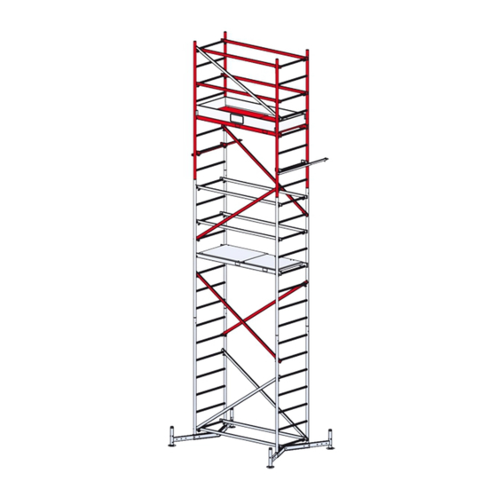
  • Seite 17 ClimTec ® Das fertige ClimTec ® • Darstellung ohne Ballastierung • Darstellung mit Fahrrollen...
  • Seite 18: Ballastierung Des Climtec

    ClimTec ® 4. Ballastierung des ClimTec ® Das ClimTec muss je nach Höhe mit Ballastgewichten oder Auslegern gegen Kippen gesichert werden. Stabilisierungssets ersetzen ® nicht die Ballastierung oder die Ausleger. Die Anzahl der Ballastgewichte oder Ausleger können Sie aus den Tabellen unten entnehmen.
  • Seite 19: Montage Ausleger

    ClimTec ® 4.3 Montage Ausleger Die optional erhältlichen Ausleger dienen zur zusätzlichen sicheren Abstützung des ClimTec . Das Anbringen der Ausleger muss mit absoluter ® Sorgfalt durchgeführt werden. Die Ausleger sind fest mit dem Gerüst zu verbinden. Die Füße der Ausleger müssen immer fest auf dem Boden stehen.
  • Seite 20 ClimTec ® Assembly Instructions and User Manual DIN EN 1298 (prEN 1004-2) Mobile scaffold tower in accordance with EN 1004-1 • Version 1.0 © 2021 KRAUSE-Werk ClimTec ClimTec Scaffold Tower Scaffold Tower ® ® Addition to ClimTec Assembly Instructions and User Manual (AI+UM) Art.-No. 561047 ®...
  • Seite 21 2.1 Assembly instructions ................23 3. ClimTec 6 m working height ................28 ® 3.1 Assembly instructions ................29 4. Attaching ballast to the ClimTec ..............35 ® 4.1 Using ballast weights ................. 36 4.2. Using outriggers ..................36 4.3 Fitting the outriggers .................. 36 5.
  • Seite 22: Assembly Instructions For Locking Bolts

    ClimTec ® 1.1 Assembly instructions for locking bolts Locking bolts, M5 x 65 Locking bolts, M5 x 85 Platform 1.2 Assembly instructions for GuardMatic-System 13 mm 5 mm...
  • Seite 23: Assembly Instructions

    ClimTec ® 2. ClimTec 4 m working height ® Pos. Name Art.-No. 1 Base frame 1.75 x 0.65 m 715067 2 Adjustable stabiliser 714008 3 Vertical section 1.00 x 0.65 m 715029 4 Diagonal bar 1.89 m 712707 5 Platform with hatch 1.50 x 0.60 m 711007 6 Horizontal brace 1.59 m...
  • Seite 24 If you are not fitting castors, please proceed with step 4. • Insert the castors and secure them with gravity pin or wing bolt. When using Art.-No. 914323 please level the ClimTec ® horizontally. Brake the castors and swivel them.
  • Seite 25 ClimTec ® Step 5 • Attach the vertical frames and lock them with the locking pins. 2 x Art.-No. 715029 4 x Art.-No. 714411 Step 6 • Take hold of the GuardMatic-System’s movable diagonal braces. • Attach the GuardMatic System to the top rungs.
  • Seite 26 • Lock the platform into place with the locking bolts. 1 x Art.-No. 711007 2 x Art.-No. 718877 Step 8 • Attach four outriggers or the required number of ballast weights. (See section 4 for information on securing the ClimTec ® with ballast weights).
  • Seite 27 • Insert the front/back boards on the inside of the vertical frames so that they come to rest on the side boards. 2 x Art.-No. 713506 2 x Art.-No. 713001 The ready assembled 4 m ClimTec ® • Shown without ballast weights • Shown with castors...
  • Seite 28 ClimTec ® 3. ClimTec 6 m working height ® Pos. Name Art.-No. 1 Base frame 1.75 x 0.65 m 715067 2 Adjustable stabiliser 714008 3 Vertical section 2.00 x 0.65 m 715012 4 Vertical section 1.00 x 0.65 m 715029 5 Diagonal bar 1.89 m...
  • Seite 29: Assembly Instructions

    If you are not fitting castors, please proceed with step 4. • Insert the castors and secure them with gravity pin or wing bolt. When using Art.-No. 914323 please level the ClimTec horizontally. Brake ® the castors and swivel them.
  • Seite 30 ClimTec ® Step 4 • Connect the two base frames by attaching the diagonal braces to the bottom rung on each base frame and to the fifth rung on the other. 2 x Art.-No. 712707 4 x Art.-No. 718860 Step 5 •...
  • Seite 31 ClimTec ® Step 6 • Take hold of the GuardMatic System’s movable diagonal braces. • Attach the GuardMatic-System to the top rungs. • Secure the moveable diagonal braces on the rungs with the locking bolts. 2 x Art.-No. 710673 Step 7 •...
  • Seite 32 ® Step 8  • Attach the four outriggers or the required number of ballast weights. (See section 4 for information on securing the ClimTec ®  with ballast weights). Step 9 • Attach the vertical frames and lock them with the locking pins.
  • Seite 33 ClimTec ® Step 10 • Take hold of the GuardMatic-System’s movable diagonal braces. • Attach the GuardMatic-System to the top rungs. • Secure the moveable diagonal braces on the rungs with the locking bolts. 2 x Art.-No. 710673 Step 11 •...
  • Seite 34 2 x Art.-No. 713506 2 x Art.-No. 713001 Step 13 If using the ClimTec at a wall: • Attach the stabilisers to the rung under- neath the topmost GuardMatic-System. • Insert the hook into a ring bolt fastened to the wall.
  • Seite 35 ClimTec ® The ready assembled 6 m ClimTec ® • Shown without ballast weights • Shown with castors...
  • Seite 36: Attaching Ballast To The Climtec

    ClimTec ® 4. Attaching ballast to the ClimTec ® Depending on its height, the ClimTec has to be protected from tipping over with either ballast weights or outriggers. Stabilisers are not a ® substitute for ballast weights or outriggers. The number of ballast weights or outriggers required are shown in the tables below.
  • Seite 37: Fitting The Outriggers

    ClimTec ® 4.3 Fitting the outriggers The optionally available outriggers are designed to give the ClimTec more stability. The outriggers always have to be fitted with the greatest ® of care. The outriggers have to be securely fastened to the scaffold. The outrigger‘s feet always have to be solidly resting on the ground. In some cases, it may be necessary to put break-proof supports underneath the outriggers to make sure they properly rest on the ground.
  • Seite 38 ClimTec ® Instrukcja montażu i użytkowania DIN EN 1298 (prEN 1004-2) Ruchoma platforma robocza zgodny z EN 1004-1 - wersja 1.0 © 2021 KRAUSE-Werk Platforma robocza ClimTec Platforma robocza ClimTec ® ® Uzupełnienie do A+V ClimTec Nr kat. 561047 ®...
  • Seite 39 2.1 Instrukcja montażu ..................41 3. ClimTec 6 m Wysokość robocza ..............46 ® 3.1 Instrukcja montażu ..................47 4. Attaching ballast to the ClimTec ..............53 ® 4.1 Balastowanie za pomocą ciężarków ............54 4.2. Balastowanie za pomocą wysięgników ............54 4.3 Montaż...
  • Seite 40: Instrukcja Montażu Zestawów Zabezpieczającychbolts

    ClimTec ® 1.1 Instrukcja montażu zestawów zabezpieczającychbolts Zestaw zabezpieczający, M5 x 65 Zestaw zabezpieczający, M5 x 85 Platforma 1.2 Instrukcja montażu GuardMatic-System 13 mm 5 mm...
  • Seite 41: Instrukcja Montażu

    ClimTec ® 2. ClimTec 4 m Wysokość robocza height ® Poz. Określenie Nr kat. Szt. 1 Rama podstawowa 1,75 x 0,65 m 715067 2 Poprzeczka przesuwna 714008 3 Rama pionowa 1,00 x 0,65 m 715029 4 Przekątna 1,89 m 712707 5 Platforma z włazem 1,50 x 0,60 m...
  • Seite 42 Jeśli wybrałeś wersję ruchomą! W przeciw- nym razie należy kontynuować od punktu 4. • Włożyć kółka i zabezpieczyć je za pomocą kołka rozporowego lub śruby motylkowej. Do Nr kat. 914323 ustawić ClimTec ® poziomo. W tym celu należy zahamować kółka i obrócić je.
  • Seite 43 ClimTec ® • Nałożyć ramy pionowe i zabezpieczyć je za pomocą wkładów. 2 x Nr kat. 715029 4 x Nr kat. 714411 • Przytrzymać GuardMatic-System za poprzeczki. • Zaczepić GuardMatic-System na górnych szczeblach. • Zabezpieczyć poprzeczki za pomocą zestawów zabezpieczających.
  • Seite 44 ClimTec ® • Zawiesić pomost na piąte szczeble od góry. • Zabezpieczyć platformę za pomocą zestawów zabezpieczających. 1 x Nr kat. 711007 2 x Nr kat. 718877 • Zamontować cztery wysięgniki lub obciążniki balastowe w wymaganej liczbie. (patrz rozdział 4 Balastowanie systemu ClimTec ®...
  • Seite 45 • Umieścić deski poprzeczne na końcach platformy. • Umieść deski podłużne wewnątrz ram pionowych na deskach poprzecznych. 2 x Nr kat. 713506 2 x Nr kat. 713001 Gotowy 4 m ClimTec ® • Ilustracja bez balastowania • Ilustracja z kółkami...
  • Seite 46 ClimTec ® 3. ClimTec 6 m Wysokość robocza ® Poz. Określenie Nr kat. Szt. 1 Rama podstawowa 1,75 x 0,65 m 715067 2 Poprzeczka przesuwna 714008 3 Rama pionowa 2,00 x 0,65 m 715012 4 Rama pionowa 1,00 x 0,65 m 715029 5 Przekątna 1,89 m...
  • Seite 47: Instrukcja Montażu

    Jeśli wybrałeś wersję ruchomą! W przeciwnym razie należy kontynuować od punktu 4. • Włożyć kółka i zabezpieczyć je za pomocą kołka rozporowego lub śruby motylkowej. Do Nr kat. 914323 ustawić ClimTec poziomo. W ® tym celu należy zahamować kółka i obrócić je.
  • Seite 48 ClimTec ® • Połączyć obie ramy podstawowe w przeciwnych kierunkach z poprzeczkami od najniższego do piątego szczebla. 2 x Nr kat. 712707 4 x Nr kat. 718860 • Nałożyć ramy pionowe i zabezpieczyć je za pomocą wkładów. 2 x Nr kat. 715029...
  • Seite 49 ClimTec ® • Przytrzymać GuardMatic-System za poprzeczki. • Zaczepić GuardMatic-System na górnych szczeblach. • Zabezpieczyć poprzeczki za pomocą zestawów zabezpieczających. 2 x Nr kat. 710673 • Zawiesić pomost na piąte szczeble od góry. • Zabezpieczyć platformę za pomocą zestawów zabezpieczających.
  • Seite 50 ClimTec ®  • Zamontować cztery wysięgniki lub obciąż- niki balastowe w wymaganej liczbie. (patrz rozdział 4 Balastowanie systemu  ClimTec ® • Nałożyć ramy pionowe i zabezpieczyć je za pomocą wkładów. 2 x Nr kat. 715012 4 x Nr kat. 714411...
  • Seite 51 ClimTec ® • Przytrzymać GuardMatic-System za poprzeczki. • Zaczepić GuardMatic-System na górnych szczeblach. • Zabezpieczyć poprzeczki za pomocą zestawów zabezpieczających. 2 x Nr kat. 710673 • Zawiesić pomost na piąte szczeble od góry. • Zabezpieczyć platformę za pomocą zestawów zabezpieczających.
  • Seite 52 ClimTec ® • Umieścić deski poprzeczne na końcach platformy. • Umieść deski podłużne wewnątrz ram pionowych na deskach poprzecznych. 2 x Nr kat. 713506 2 x Nr kat. 713001 Przy zastosowaniu jako rusztowanie przyścienne: • Zamontować zestaw stabilizujący na szczeblach poniżej górnego GuardMatic-System.
  • Seite 53 ClimTec ® Gotowy 6 m ClimTec ® • Ilustracja bez balastowania • Ilustracja z kółkami...
  • Seite 54: Attaching Ballast To The Climtec

    ClimTec ® 4. Attaching ballast to the ClimTec ® W zależności od wysokości, rusztowanie ClimTec musi być zabezpieczone przed przewróceniem się za pomocą balastów lub wysięgników. ® Zestawy stabilizujące nie zastępują balastowania ani wysięgników. Liczbę obciążników balastowych lub wysięgników można znaleźć w poniższych tabelach.
  • Seite 55: Montaż Wysięgnika

    ClimTec ® 4.3 Montaż wysięgnika Opcjonalnie dostępne wysięgniki zapewniają dodatkowe bezpieczne podparcie dla ClimTec . Mocowanie wysięgników musi być ® wykonywane z absolutną ostrożnością. Wysięgniki muszą być stabilnie połączone z rusztowaniem. Stopy wysięgników muszą zawsze stać stabilnie na podłożu. W razie potrzeby należy stosować podkłady odporne na uderzenia i wyrównujące wysokość.
  • Seite 56 561118 © 2021 by KRAUSE-Werk D-36304 Alsfeld. Technische Änderungen, Druckfehler und Irrtümer vorbehalten. EXTRAS und Arbeitsmittel sind nicht im Lieferumfang enthalten! The information presented in this document is subject to changes, printing errors and omissions. EXTRAS and work equipment are not included with the scaffold tower!

Diese Anleitung auch für:

710383710369710338710390710376710345

Inhaltsverzeichnis