Minebea Intec MP30 Kurzprogrammierung
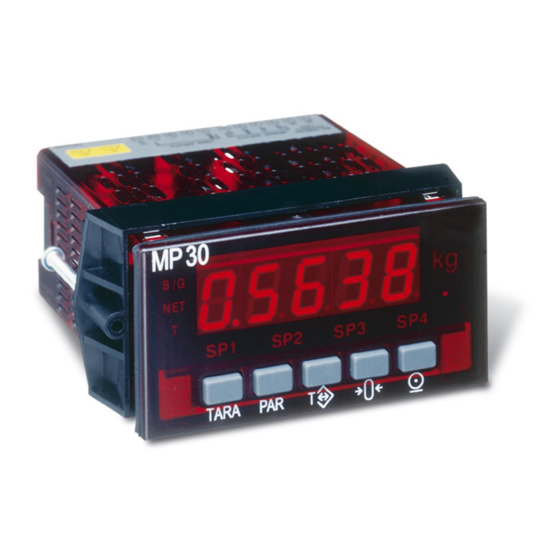
1/8 din digital weight indicator
Inhaltsverzeichnis
Verfügbare Sprachen
Verfügbare Sprachen
Quicklinks
Bulletin No. MP30QS-B
Drawing No. LP0479
Released 3/05
]
STEP 1
◊ ◊ MP30 indicator
◊ ◊ Mounting Kit (attached to the indicator)
◊ ◊ Panel Gasket (loose black rubber frame)
◊ ◊ User's Bulletin
◊ ◊ Accessories
]
STEP 2
Remove the indicator base from the case by firmly
depressing and pulling back on the side rear base
finger tabs. This should lower the base latches behind
the case slot. Get one side started then do the other
side and pull back. The mounting kit bracket could be
removed later.
]
STEP 3
Three with MP30 (Jumpers are moved later)
Jumpers are black thin clips which
pull up and down over gold pins.
The Top View will be used in this
step to show where to place the
jumpers. (The selections are not
labeled on the main board.)
]
STEP 4
BRIDGE EXCITATION
Example: 10 volt *
Verify one jumper is in 10 V position.
* If needing a 5 volt excitation then move the jumper to the lower position.
FRONT DISPLAY REVIEW Step 3
BRIDGE
5V
OR
10 V
EXCITATION
]
STEP 5
Reassemble the indicator base into the case. (Reverse Step 2)
]
STEP 6
There are no power or configuration switches nor adjustment potentiometers on this indicator.
Quick Start Guide
MODEL MP30
Congratulations on your purchase of Sartorius products.
This Quick Start Guide describes steps to help you start-up the MP30 indicator.
Identify Jumpers
FRONT DISPLAY
Main
Circuit
Board
JUMPER
JUMPER
LOCATION
LOCATION
BRIDGE
REAR TERMINALS
Keep
Choose Next
=Jumper
REAR
Reassemble Case
1/8 DIN DIGITAL WEIGHT INDICATOR
MINEBEA INTEC products.
Unpack
CAUTION: Read the complete instructions in
the step before performing the step.
Open Case
Mounting
Kit
FRONT
LEDS
SIDE VIEW
Cardboard
Step
SIGNAL INPUT
4
USER INPUT
Area
Move Jumpers
* If using a 240 mV input then move the jumper to the lower position.
Switches
Latch
FRONT
Pull
LEDS
Tab
Depress
Pull up
Black
Thin
Jumper
Gold
Pins
BOARD LEVEL VIEW
CAUTION: These jumpers must be in the correct
position for the particular application before
applying Power or Input Signal to the indicator.
Do not move User Input jumper for this start-up.
INPUT RANGE
Example: 24 mV input *
Move one jumper to 24 mV position.
FRONT DISPLAY REVIEW Step 3
INPUT
24 mV
OR
OR
Choose
240 mV
Before
RANGE
REAR
Mounting
Kit
Pull
Pull
SIDE VIEW
Jumper
Over Pins
Gold Pin
Exposed
TOP VIEW
Keep
=Jumper
Inhaltsverzeichnis
Fehlerbehebung

Verwandte Anleitungen für Minebea Intec MP30


Inhaltszusammenfassung für Minebea Intec MP30
-
Seite 5: Kurzprogrammierung
Kurzprogrammierung Für die 48 x 96 mm Gewichtsanzeige MP 30 MINEBEA INTEC einzusetzen und gratulieren Ihnen zu diesem Entschluss. Wir danken Ihnen für Ihren Entscheidung, ein Produkt von Sartorius einzusetzen und gratulieren Ihnen zu diesem Entschluß. Mit dieser Kurzanleitung können Sie das MP 30 schnell in Betrieb nehmen. -
Seite 6: Gerät Einschalten
Anschluß von Spannungsversorgung und Signal Schritt 7 Bitte schließen Sie die entsprechende Spannungsversorgung an den Klemmen 1 und 2 an. Bitte schließen Sie das Eingangssignal gemäß den folgenden Zeichnungen an. Drehen Sie die Schrauben im Uhrzeigersinn bis die Kabel fest sind. Klemme 3: + Signal, Klemme 4: - Signal, Klemme 5: Masse, Klemme 6: Brückenversorgung.