WIKA F-20 Betriebsanleitung
Vorschau ausblenden
Andere Handbücher für F-20:
- Betriebsanleitung (17 Seiten) ,
- Betriebsanleitung (18 Seiten)

Verwandte Anleitungen für WIKA F-20


Inhaltszusammenfassung für WIKA F-20
- Seite 1 Operating instructions Betriebsanleitung Pressure transmitter, models F-20 and F-21 Druckmessumformer, Typen F-20 und F-21 Pressure transmitter models F-20, F-21...
- Seite 17 Inhalt Inhalt 1. Allgemeines 2. Funktion 3. Sicherheit 4. Verpackung 5. Inbetriebnahme, Betrieb 6. Technische Daten 7. Einstellung Nullpunkt / Spanne 8. Wartung 9. Störbeseitigung 10. Lagerung, Entsorgung WIKA Betriebsanleitung Druckmessumformer, Typen F-20, F-21...
-
Seite 18: Allgemeines
Fax: +49 9372 132-406 info@wika.de Abkürzungen 2-Leiter Zwei Anschlussleitungen dienen zur Spannungsversorgung. Der Speisestrom ist das Mess-Signal. 3-Leiter Zwei Anschlussleitungen dienen zur Spannungsversorgung. Eine Anschlussleitung dient für das Mess-Signal. Positiver Versorgungsanschluss Negativer Versorgungsanschluss Positiver Messanschluss WIKA Betriebsanleitung Druckmessumformer, Typen F-20, F-21... -
Seite 19: Funktion
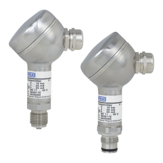
2. Funktion / 3. Sicherheit 2. Funktion F-20: Druckanschluss mit innenliegender Membran (Standardausführung). F-21: Druckanschluss mit frontbündiger Membrane für hochviskose oder kristallisierende Medien, die die Bohrung des Druckanschlusses zusetzen können. Mittels Sensorelement und unter Zuführung von Hilfsenergie wird über die Verformung einer Membran der anstehende Druck in Ihrer Anwendung in ein verstärktes standardisiertes elektrisches Signal umgewandelt. -
Seite 20: Personalqualifikation
Ergreifen Sie Vorsichtsmaßnahmen für Messstoffreste in ausgebauten Druckmessgeräten. ■ Messstoffreste können zur Gefährdung von Menschen, Umwelt und Einrichtung führen! Lassen Sie Reparaturen nur vom Hersteller durchführen. ■ Öffnen Sie den Stromkreis, bevor Sie den Stecker / Deckel abnehmen. ■ WIKA Betriebsanleitung Druckmessumformer, Typen F-20, F-21... -
Seite 21: Verpackung
Untersuchen Sie das Druckmessgerät auf eventuell entstandene Transportschäden. Sind offensichtlich Schäden ■ vorhanden, teilen Sie dies dem Transportunternehmen und WIKA unverzüglich mit. Bewahren Sie die Verpackung auf, denn diese bietet bei einem Transport einen optimalen Schutz (z. B. wechselnder ■... - Seite 22 4 ... 20 mA Anschlussbelegung Testkreisanschluss 4 ... 20 mA Test DC 11 ... 30 V Spannungsversorgung S# 0639110 Serien-Nr. P# 0639080 Erzeugnis-Nr. Codiertes WIKA Alexander Wiegand SE & Co. KG 63911 Klingenberg Made in Germany Herstelldatum WIKA Betriebsanleitung Druckmessumformer, Typen F-20, F-21...
-
Seite 23: Montage Elektrischer Anschluss
Entfernen Sie die Schutzkappe erst kurz vor dem Einbau und achten Sie unbedingt darauf, dass die ■ Membran auch während des Einbaus nicht beschädigt wird (F-21). Bei Typ F-20 müssen Sie eine Dichtung vorsehen; Ausnahme sind Geräte mit selbstdichtendem ■ Gewinde (z. B. NPT-Gewinde). Bei Typ F-21 ist der Dichtring im Lieferumfang enthalten. -
Seite 24: Elektrischer Anschluss
Funktion des Testkreises für 2-Leiter Anhand des Testkreises ist es möglich, während des normalen Betriebes eine Strommessung durchzuführen ohne das Gerät abzuklemmen. Sie müssen hierzu ein Amperemeter (Innenwiderstand < 15 Ohm) an die Klemmen Test +/- anschließen. WIKA Betriebsanleitung Druckmessumformer, Typen F-20, F-21... -
Seite 25: Technische Daten
% d. Spanne ≤ 0,2 (bei Referenzbedingungen) Zulässige Temperaturbereiche Messstoff °C -30 ... +100 {-40 ... +125} ■ Umgebung °C -20 ... +80 {-30 ... +105} ■ Lagerung °C -40 ... +100 ■ Nenntemperaturbereich °C 0 ... +80 WIKA Betriebsanleitung Druckmessumformer, Typen F-20, F-21... -
Seite 26: Funktionsprüfung
Das Ausgangssignal muss sich dem anstehenden Druck proportional verhalten. Wenn dies nicht so ist, kann das ein Hinweis auf eine Beschädigung der Membran sein. Lesen Sie in diesem Fall in Kapitel 9 „Störbeseitigung“ nach. WIKA Betriebsanleitung Druckmessumformer, Typen F-20, F-21... -
Seite 27: Einstellung Nullpunkt / Spanne
Wenn der Nullpunkt nicht stimmt ggf. Prozedur wiederholen. ■ Schließen Sie das Druckmessgerät wieder sorgfältig. Achten Sie darauf, dass die Dichtungen unbeschädigt und ■ sauber sind und auf die korrekte Lage der Dichtungen, um die Schutzart zu gewährleisten. WIKA Betriebsanleitung Druckmessumformer, Typen F-20, F-21... -
Seite 28: Wartung
Messstoffreste können zur Gefährdung von Menschen, Umwelt und Einrichtung führen! Setzen Sie das Druckmessgerät außer Betrieb und schützen Sie es gegen versehentliche ■ Inbetriebnahme, wenn Sie Störungen nicht beseitigen können. Lassen Sie Reparaturen nur vom Hersteller durchführen. ■ WIKA Betriebsanleitung Druckmessumformer, Typen F-20, F-21... -
Seite 29: Mögliche Ursache
Ausfall Rücksprache mit Hersteller *) Signalspanne schwankend EMV-Störquellen in Umgebung, z. B. Frequenzumrichter Gerät abschirmen; Leitungsabschirmung; Störquelle entfernen Abweichendes Nullpunkt- Membranbeschädigung, z. B. durch Schläge, Gerät austauschen Signal abrasives/agressives Medium; Korrosion an Membran/ Druckanschluss WIKA Betriebsanleitung Druckmessumformer, Typen F-20, F-21... - Seite 30 Eine solche Erklärung beinhaltet alle Materialien, welche mit dem Gerät in Berührung kamen, auch solche, die zu Testzwecken, zum Betrieb oder zur Reinigung eingesetzt wurden. Das Rücksendeformular ist über unsere Internet- Adresse (www.wika.de / www.wika.com) verfügbar. WIKA Betriebsanleitung Druckmessumformer, Typen F-20, F-21...
-
Seite 31: Entsorgung
Montieren Sie die Schutzkappe bei Lagerung des Druckmessgerätes, damit die Membran nicht beschädigt wird (F-21). Entsorgung Entsorgen Sie Gerätekomponenten und Verpackungsmaterialien entsprechend den einschlägigen landesspezifischen Abfallbehandlungs- und Entsorgungsvorschriften des Anliefergebietes. Nicht mit dem Hausmüll entsorgen. Für eine geordnete Entsorgung gemäß nationaler Vorgaben sorgen. WIKA Betriebsanleitung Druckmessumformer, Typen F-20, F-21... - Seite 32 WIKA subsidiaries worldwide can be found online at www.wika.com. WIKA Niederlassungen weltweit finden Sie online unter www.wika.de. WIKA Alexander Wiegand SE & Co. KG Alexander-Wiegand-Strasse 30 63911 Klingenberg • Germany Tel. +49 9372 132-0 Fax +49 9372 132-406 info@wika.de www.wika.de...