Inhaltsverzeichnis
Werbung
Verfügbare Sprachen
Verfügbare Sprachen
Quicklinks
Werbung
Kapitel
Inhaltsverzeichnis

Verwandte Anleitungen für Sachtler ENG75/2 D HD


Inhaltszusammenfassung für Sachtler ENG75/2 D HD
- Seite 1 ENG 75/2 D HD Tripod Part No. S2034-0001 www.sachtler.com...
- Seite 2 Copyright © 2014 All rights reserved. Original Instructions: English All rights reserved throughout the world. No part of this document may be stored in a retrieval system, transmitted, copied or reproduced in any way, including, but not limited to, photocopy, photograph, magnetic or other record without the prior agreement and permission in writing of the Vitec Group plc.
-
Seite 3: Inhaltsverzeichnis
Contents Safety..........2 General Notices . -
Seite 4: Safety
Safety Important information on the safe installation and operation of this WARNING! Toppling hazard. Do not leave unattended. product. Read this information before operating the product. For Keep out of reach of children. your personal safety, read these instructions. Do not operate the product if you do not understand how to use it safely. -
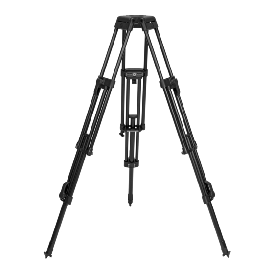
Seite 5: Components
Components ENG 75/2 D HD Tripod Description Upper leg clamp lever Bungee cord hook Safety sleeve Rubber feet 75 x 3 (optional) Double-spiked foot Lower leg clamp lever Mid-level spreader 75 HD (optional) Ground spreader SP (optional) -
Seite 6: Mid-Level Spreader 75 Hd (Optional S2038-1000)
Components Mid-level Spreader 75 HD (optional S2038-1000) Ground Spreader SP 75 (optional 7001) Description Description HIGH/LOW profile knob Spreader lock Pull up ring Pull up ring Spreader lock Spreader foot Spreader attachment hook Spreader arm Red attach/release button Spreader arm... -
Seite 7: Assembly
Assembly Setting up the Tripod Detach the bungee cord hook to release the legs. CAUTION! Use the spreader to ensure the tripod legs are spread sufficiently, so that the Centre of Gravity of the tilted payload remains within the footprint of the tripod. Use the tie-down hook on the tripod for additional stability. - Seite 8 Assembly Extend the upper stage by lifting the clamp levers and adjusting Adjust the operating height by flipping down the leg clamp levers the height of the tripod as required. When complete, push down on the lower stage and pulling the tripod up to the desired height. the clamp levers, until they snap into the ‘locked’...
-
Seite 9: Attaching The Mid-Level Spreader 75 Hd
Assembly Attaching the rubber feet 75 Attaching the mid-level spreader 75 HD Place the rubber foot between the spikes. Check the markings on CAUTION! Ensure that the red attach/release button is fully the foot for orientation. The ‘INSIDE’ marking must be turned out after attaching the spreader to the tripod. -
Seite 10: Attaching The Ground Spreader Sp 75
Assembly Attaching the ground spreader SP 75 Setting up the mid-level spreader 75 HD Place the ground spreader on the floor and open out the legs. Pull up the ring in the centre of the spreader. Adjust the profile Place the spikes of the tripod between the foot moulding on the setting to either HIGH (45°) or LOW (flat) and arrest the tripod legs ground spreader. -
Seite 11: Setting Up The Ground Spreader Sp 75
Assembly Setting up the ground spreader SP 75 If required, unlock the spreader locks to allow the spreader arms Unlock the spreader locks to allow the spreader arms to extend. to extend as necessary. Tighten the spreader locks. Adjust the tripod footprint, as required. Tighten the spreader locks. -
Seite 12: Transportation
Transportation Attaching the bungee cord hook The bungee cord hook is used to secure the tripod legs together when in transit and is housed underneath the base of an upper leg. When the tripod is collapsed, the bungee cord hook can be stretched around the upper legs and clipped onto the leg assembly. -
Seite 13: Maintenance
Contact (refer to Adjusting the leg clamps on page 12). Sachtler headquarters, your local Sachtler office or representative. • Check the effectiveness of the locking bolts. The bolts should... -
Seite 14: Adjusting The Leg Clamps
Maintenance Adjusting the leg clamps CAUTION! Do NOT over-adjust the clamp lever mechanism to support more than 66 lbs (30 kg) as this will cause damage to the tripod. Should the leg clamps become ineffective, they may require adjustment (refer to Checking the effectiveness of the leg clamps on page 11). To adjust the leg clamp mechanism proceed as follows: Set the clamp lever to the ‘unlocked’... -
Seite 15: Technical Specification
Technical Specification ENG 75/2 D HD Tripod (S2034-0001) Mid-level Spreader 75 HD (optional S2038-1000) Bowl Weight 75 mm 0.49 kg (1 lb) Max Payload Transport Length 35 kg (77 lbs) 24.6 cm (9.6in.) Build-up Radius - Flat Weight 23.1 cm (23.2 in.) to 38.3 cm (61.4 in.) 3.1 kg (6.8 lbs) Build-up Radius - 45 Degrees With Ground Spreader SP 75... -
Seite 16: General Notices
Vitec Videocom Limited declares that this product has been manufactured in accordance with BS EN ISO 9001:2008 and is in Sachtler reserve the right to make changes to product design and compliance with the essential requirements and other relevant performance as technology advances. - Seite 17 Inhalt Sicherheit ..........16 Allgemeine Hinweise .
-
Seite 18: Sicherheit
Sicherheit Wichtige Informationen zur sicheren Montage und Verwendung ACHTUNG! Stolpergefahr. Einsatzradius des Stativs dieses Produkts. Lesen Sie diese Informationen, bevor Sie das entsprechend der Drehumgebung einstellen. Produkt verwenden. Lesen Sie diese Anweisungen zu Ihrer persönlichen Sicherheit. Das Produkt nicht verwenden, wenn Sie ACHTUNG! Sturzgefahr. -
Seite 19: Komponenten
Komponenten Stativ ENG 75/2 D HD Beschreibung Oberer Klemmhebel Gummizughaken Sicherheitshülle Gummifüße 75 x 3 (optional) Doppel-Spike-Fuß Unterer Klemmhebel Mittelspinne 75 HD (optional) Bodenspinne SP (optional) -
Seite 20: Mittelspinne 75 Hd (Optional S2038-1000)
Komponenten Mittelspinne 75 HD (optional S2038-1000) Bodenspinne SP 75 (optional 7001) Beschreibung Beschreibung Drehknopf Profil HOCH/NIEDRIG Spinnensicherung Zugring Zugring Spinnensicherung Spinnenfuß Spinnenmontagehaken Spinnenarm Roter Knopf zum Anbringen/Abnehmen Spinnenarm... -
Seite 21: Montage
Montage Aufstellen des Stativs Nehmen Sie den Gummizughaken ab, um die Beine zu lösen. VORSICHT! Verwenden Sie die Spinne, um sicherzustellen, dass die Beine des Stativs ausreichend gespreizt sind, sodass der Schwerpunkt der geneigten Traglast innerhalb des Einsatzradius des Stativs verbleibt. Verwenden Sie den Fixierungshaken des Stativs für zusätzliche Stabilität. - Seite 22 Montage Ziehen Sie die erste Stufe heraus, indem Sie die Klemmhebel Passen Sie die Arbeitshöhe an, indem Sie die Klemmhebel der öffnen und die Höhe des Stativs wie gewünscht einstellen. Wenn unteren Stufe öffnen und das Stativ bis zur gewünschten Höhe Sie fertig sind, drücken Sie auf den Klemmhebel, bis sie in der herausziehen.
-
Seite 23: Anbringen Der Mittelspinne 75 Hd
Montage Anbringen der Mittelspinne 75 HD Anbringen der Gummifüße 75 Platzieren Sie den Gummifuß zwischen den Spike-Füßen. VORSICHT! Stellen Sie sicher, dass die rote Taste zum Orientieren Sie sich an den Markierungen am Fuß. Die Markierung Anbringen/Abnehmen nach dem Anbringen der Spinne am ‘INSIDE’... -
Seite 24: Anbringen Der Bodenspinne Sp 75
Montage Anbringen der Bodenspinne SP 75 Einrichten der Mittelspinne 75 HD Platzieren Sie die Bodenspinne auf dem Boden und öffnen Sie die Ziehen Sie den Ring in der Mitte der Spinne hoch. Stellen Sie das Beine. Platzieren Sie die Spike-Füße des Stativs in den Profil entweder auf HIGH (45°) oder LOW (flach) ein und fixieren Fußausbuchtungen der Bodenspinne. -
Seite 25: Einrichten Der Bodenspinne Sp 75
Montage Einrichten der Bodenspinne SP 75 Falls nötig, lösen Sie die Spinnenverriegelungen, damit die Lösen Sie die Spinnenverriegelungen, damit die Spinnenarme Spinnenarme so weit wie nötig ausgezogen werden können. ausgezogen werden können. Passen Sie den Einsatzradius des Ziehen Sie die Spinnenverriegelungen fest. Stativs wie gewünscht an. -
Seite 26: Transport
Transport Anbringen des Gummizughakens Der Gummizughaken wird verwendet, um die Stativbeine für den Transport zu fixieren und befindet sich an den Beschlägen eines oberen Beines. Ist das Stativ zusammengeklappt, kann der Gummizughaken um die oberen Beine gezogen und an den Beinen befestigt werden. -
Seite 27: Pflege Und Wartung
Sie diese falls nötig erneut ein (siehe Anpassen der sollten nur von geschultem Fachpersonal durchgeführt werden. Beinklemmen auf Seite 26). Wenden Sie sich an die Sachtler-Zentrale, Ihre örtliche Sachtler- • Überprüfen Sie die Effektivität der Verriegelungsbolzen. Die Niederlassung oder Ihren örtlichen Ansprechpartner. -
Seite 28: Anpassen Der Beinklemmen
Pflege und Wartung Anpassen der Beinklemmen VORSICHT! Stellen Sie den Klemmhebelmechanismus nicht auf eine Traglast von mehr als 30 kg ein, da dies zu Schäden am Stativ führt. Sollten die Beinklemmen nicht länger zuverlässig funktionieren, müssen sie möglicherweise neu eingestellt werden (siehe Überprüfung der Effektivität der Beinklemmen auf Seite 25). -
Seite 29: Technische Daten
Technische Daten Stativ ENG 75/2 D HD (S2034-0001) Mittelspinne 75 HD (optional S2038-1000) Schale Gewicht 75 mm 0,49 kg Maximale Traglast Transportlänge 35 kg 24,6 cm Einsatzradius - Flach Gewicht 23,1 cm bis 38,3 cm 3,1 kg Einsatzradius - 45 Grad Mit Bodenspinne SP 75 11,8 cm bis 19,1 cm 44 cm bis 155 cm... -
Seite 30: Allgemeine Hinweise
Vitec Videocom Limited erklärt, dass dieses Produkt gemäß BS EN ISO 9001:2008 hergestellt wurde und die notwendigen Anforderungen und Sachtler behält sich das Recht vor, im Rahmen des technologischen anderen relevanten Bestimmungen der EU-Maschinenrichtlinie 2006/ Fortschritts Änderungen am Produktdesign und seiner Leistung 42/EG erfüllt. - Seite 31 Publication part No. S2034-4980/1 www.sachtler.com...