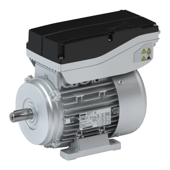
Lenze Smart Motor m300 Bedienungsanleitung
Drehstrommotoren
Vorschau ausblenden
Andere Handbücher für Smart Motor m300:
- Montageanleitung (116 Seiten) ,
- Montage- und einschaltanleitung (76 Seiten)
Inhaltsverzeichnis
Verfügbare Sprachen
Verfügbare Sprachen
Quicklinks
Kapitel
Inhaltsverzeichnis

Verwandte Anleitungen für Lenze Smart Motor m300


Inhaltszusammenfassung für Lenze Smart Motor m300
- Seite 1 Drehstrommotoren Lenze Smart Motor m300 Three-phase AC motors Lenze Smart Motor m300...
- Seite 3 DE - Lenze Smart Motor m300 EN - Lenze Smart Motor m300...
-
Seite 5: Inhaltsverzeichnis
Inhalt Inhalt Über dieses Dokument Dokumentbeschreibung Weiterführende Dokumente Schreibweisen und Konventionen Sicherheitshinweise Grundlegende Sicherheitshinweise Bestimmungsgemäße Verwendung Restgefahren Produktinformation Identifizierung der Produkte Typenschilder Produktcodes Ausstattung Transport Lagerung Mechanische Installation Wichtige Hinweise Vorbereitung Aufstellung Abmessungen Montage Elektrische Installation Wichtige Hinweise Vorbereitung Netzanschluss Anschluss nach EN Anschluss nach cULus Motoranschluss... - Seite 6 Inhalt Technische Daten Normen und Einsatzbedingungen Konformitäten und Approbationen Personenschutz und Geräteschutz Angaben zur EMV Umweltbedingungen Netzbedingungen Bemessungsdaten Ökodesign-Richtlinie Umwelthinweise und Recycling...
-
Seite 7: Über Dieses Dokument
• Alle Personen, die an und mit den Antrieben arbeiten, müssen bei ihren Arbeiten die Dokumentation ver- fügbar haben und die für sie wesentlichen Angaben und Hinweise beachten. • Die Dokumentation muss immer komplett und in einwandfrei lesbarem Zustand sein. Weiterführende Dokumente Informationen und Hilfsmittel rund um die Lenze-Produkte finden Sie im Internet: www.Lenze.com à Downloads... -
Seite 8: Schreibweisen Und Konventionen
Über dieses Dokument Schreibweisen und Konventionen Schreibweisen und Konventionen Zur Unterscheidung verschiedener Arten von Informationen werden in diesem Dokument Konventionen ver- wendet. Zahlenschreibweise Dezimaltrennzeichen Punkt Werden generell als Dezimalpunkt dargestellt. Beispiel: 1 234.56 Warnhinweise UL-Warnhinweise Werden in englischer und französischer Sprache verwendet. UR-Warnhinweise Textauszeichnung Engineering Tools... -
Seite 9: Sicherheitshinweise
Sicherheitshinweise Bestimmungsgemäße Verwendung Sicherheitshinweise Grundlegende Sicherheitshinweise Wenn Sie die folgenden grundlegenden Sicherheitshinweise missachten, kann dies zu schweren Personen- schäden und Sachschäden führen! • Das Produkt ausschließlich bestimmungsgemäß verwenden. • Das Produkt niemals trotz erkennbarer Schäden in Betrieb nehmen. • Das Produkt niemals technisch verändern. •... -
Seite 10: Restgefahren
Sicherheitshinweise Restgefahren Restgefahren Auch wenn gegebene Hinweise beachtet und Schutzmaßnahmen angewendet werden, können Restrisiken verbleiben. Die genannten Restgefahren muss der Anwender in der Risikobeurteilung für seine Maschine/Anlage berück- sichtigen. Nichtbeachtung kann zu schweren Personenschäden und Sachschäden führen! Produkt Beachten Sie die Warnschilder auf dem Produkt und deren Bedeutung! Gefährliche elektrische Spannung: Vor Arbeiten am Produkt überprüfen, ob alle Leistungsanschlüsse spannungslos sind! Die Leistungsanschlüsse führen nach Netzausschalten für die bei dem Symbol angegebene Zeit gefährliche... -
Seite 11: Produktinformation
Produktinformation Typenschilder Produktinformation Identifizierung der Produkte Typenschilder 16.1 16.2 16.4 16.5 r/min 16.3 14.1 cos j 16.6 14.2 16.10 10.2 10.3 20.1 Position Inhalt Position Inhalt Hersteller / Produktionsstandort Bemessungsdaten für verschiedene Frequenzen Motorart / Norm 16.1 Hz= Frequenz 16.2 kW= Motorleistung Motortyp 16.3... -
Seite 12: Produktcodes
Produktinformation Ausstattung Produktcodes Produktcode Motor Beispiel Bedeutung Variante Produktcode Produktfamilie Motor Produktart Smart Motor Kühlung Eigenlüfter Interner Schlüssel Anbauten Ohne Anbauten Bremse Baugröße Baulänge Polpaarzahl 4−polige Motoren Ausführungsvariante Interner Schlüssel Approbation CE; UKCA CE; UKCA; cULus CE; UKCA; CCC CE; UKCA; cULus; CCC Ausstattung Die folgende Abbildung gibt eine Übersicht der Elemente und Anschlüsse am Produkt. -
Seite 13: Transport
Transport Transport • Für einen sachgemäßen Umgang sorgen. • Auf sicher montierte Bauteile kontrollieren. Lose Bauteile sichern oder entfernen. • Nur sicher angebrachte Transporthilfen einsetzen (z. B. Ringschrauben oder Tragbleche). • Beim Transport keine Bauelemente beschädigen. • Elektrostatische Entladungen an elektronischen Bauelementen und Kontakten verhindern. •... -
Seite 14: Lagerung
Lagerung Lagerung Lagerung bis zu einem Jahr: • Möglichst in der Herstellerverpackung • In trockener, schwingungsarmer Umgebung ohne aggressive Atmosphäre • Vor Staub und Stößen schützen • Klimatische Bedingungen gemäß den technischen Daten einhalten 4Umweltbedingungen ^ 41... -
Seite 15: Mechanische Installation
Dokumentation entnehmen. • Umgebungsmedien − insbesondere chemisch aggressive − können Wellendichtringe, Lacke und Kunst- stoffe angreifen. • Lenze bietet einen speziellen Oberflächen‐ und Korrosionsschutz. Vorbereitung • Wellendichtringe vor dem Kontakt mit Lösungsmitteln schützen. • Schutzkappen von den Wellen entfernen. -
Seite 16: Mechanische Installation Montage
Mechanische Installation Montage Montage Übertragungselemente • Nur mit geeigneten Vorrichtungen auf- oder abziehen. • Zum Aufziehen die Zentrierbohrung in der Welle verwenden. • Stöße und Schläge vermeiden. • Bei Riementrieb den Riemen nach Herstellerangaben kontrolliert spannen. • Auf verspannungsfreie Montage achten. •... -
Seite 17: Elektrische Installation
Elektrische Installation Vorbereitung Elektrische Installation Wichtige Hinweise GEFAHR! Verletzungsgefahr und Verbrennungsgefahr durch gefährliche Spannung An den Leistungsklemmen kann auch im ausgeschalteten Zustand oder bei gestopptem Motor Spannung anliegen und lebensbedrohliche Herzrhythmusstörungen und schwere Verbrennungen verursachen. ▶ Trennen Sie das Produkt vom Netz. ▶... -
Seite 18: Netzanschluss
Elektrische Installation Netzanschluss Anschluss nach EN Netzanschluss Anschluss nach EN Die folgenden Daten sind für einen 3-phasigen Netzanschluss mit 400 V gültig. Netzanschluss QUICKON-Steckverbinder Motor MSEMA☐☐063-42 MSEMA☐☐080-32 Anschluss Verlegeart Anschlusstyp QUICKON-Steckverbinder Leitungsausführung flexibel Leitungsquerschnitt Typ. Min. Max. Netzanschluss M15-Steckverbinder Motor MSEMA☐☐063-42 MSEMA☐☐080-32 Anschluss... - Seite 19 Elektrische Installation Netzanschluss Anschluss nach EN Anschluss Einzelantrieb nach EN IEC 60204‑1 3/N/PE AC 400/480 V SELV/PELV F1 … F3 F1 … F3 DC 24 V (+19.2 … +28.8 V) max. 50 mA n. c. L2 L3 Rb1 Rb2 L2 L3 Rb1 Rb2 ①...
- Seite 20 Elektrische Installation Netzanschluss Anschluss nach EN Anschluss Gruppenantrieb nach EN IEC 60204‑1 F1 … F3 PE L1 L2 L3 PE L1 L2 L3 PE L1 L2 L3 PE L1 L2 L3 PE L1 L2 L3 Max. Summe der Netz-Bemessungsströme bei 40 °C bei unterschiedlichen Leitungsquerschnitten Leitungsinstallation nach EN IEC 60204‑1...
-
Seite 21: Anschluss Nach Culus
Elektrische Installation Netzanschluss Anschluss nach cULus Anschluss nach cULus Die folgenden Daten sind für einen 3-phasigen Netzanschluss mit 480 V gültig. Netzanschluss QUICKON-Steckverbinder Motor MSEMA☐☐063-42 MSEMA☐☐080-32 Anschluss Anschlusstyp QUICKON-Steckverbinder Leitungsquerschnitt Typ. Min. Max. Netzanschluss M15-Steckverbinder Motor MSEMA☐☐063-42 MSEMA☐☐080-32 Anschluss Anschlusstyp M15-Steckverbinder Leitungsquerschnitt Typ. - Seite 22 Elektrische Installation Netzanschluss Anschluss nach cULus Allgemeine UL-Hinweise WARNUNG! ▶ UL marking ▶ Use 75 °C copper wire only, except for control circuits. ▶ Maximum conductor size is AWG14. ▶ Cord connected drives are for use only in NFPA 79 applications. ▶...
- Seite 23 Elektrische Installation Netzanschluss Anschluss nach cULus Sicherungsdaten (F1 ... F3) Motor MSEMA☐☐063-42 MSEMA☐☐080-32 Leitungsinstallation nach NFPA 70, NFPA 79 Schmelzsicherung Norm UL 248 Typ. Bemessungsstrom Max. Bemessungsstrom Halbleitersicherung Norm UL 248 Typ. Bemessungsstrom Max. Bemessungsstrom Sicherungsautomat Norm UL 489 Typ. Bemessungsstrom Max.
- Seite 24 Elektrische Installation Netzanschluss Anschluss nach cULus Max. Summe der Netz-Bemessungsströme bei 40 °C bei unterschiedlichen Leitungsquerschnitten Leitungsinstallation nach NFPA 70, NFPA 79 Hauptleitung Leitungsquerschnitt Stichleitung Leitungsquerschnitt Schmelzsicherung Typ. Bemessungsstrom Max. Bemessungsstrom Sicherungsautomat Typ. Bemessungsstrom Max. Bemessungsstrom ≥ I 12.0 N... 4Bemessungsdaten ^ 41 •...
-
Seite 25: Motoranschluss
Elektrische Installation Motoranschluss Anschluss über M15-Steckverbinder Motoranschluss Um den Motor richtig anzuschließen, beachten Sie: • Die Hinweise im Motorklemmenkasten. • Die Hinweise in der Projektierungsunterlage des Motors. • Die technischen Daten auf dem Motortypenschild. Anschluss über Klemmenkasten Klemmenkasten MSEMA Kontakt Bezeichnung Bedeutung Netzanschluss Phase L1... -
Seite 26: Anschluss Über M12-Steckverbinder
Elektrische Installation Motoranschluss Anschluss über M12-Steckverbinder Anschluss über M12-Steckverbinder HINWEIS In der Ausführung "DI/DO-GND bridged" sind die Massen der Steueranschlüsse X1 und X2 (GND-I und GND- O) miteinander verbunden. Wird nur eine Drehzahl verwendet, ist der Anschluss an X2 ausreichend. Steueranschluss X1 M12 A-codiert X1 Kontakt... -
Seite 27: Inbetriebnahme
Inbetriebnahme Inbetriebnahme Sie haben zwei Möglichkeiten, den Lenze Smart Motor an die Anwendungen anzupassen: Voraussetzungen NFC-fähiges Smartphone oder Tablet • Android-Version ab V3.0 • Lenze-App "Lenze Smart Motor" - Download von www.Lenze.com oder aus dem Google-Store • Motor spannungsfrei schalten •... -
Seite 28: Parametersatzverwaltung
Abtriebsdrehzahl 2 [0] r/min STOP: 0 r/min [500/i ... 2600/i] r/min Rechtslauf: > 0 r/min Abtriebsdrehzahl 3 Lenze Smart Motor mit Getriebe: Die Über- Abtriebsdrehzahl 4 setzung i wird bei der Berechnung der Abtriebsdrehzahl 5 Abtriebsdrehzahl berücksichtigt. Hochlaufzeit [0.0 ... 20.0] s... -
Seite 29: Gerätedaten
Inbetriebnahme Logbuch Parameter Wert Bemerkung Name Auslieferung Einstellbereich Fehlermeldung 1 (letzte) [Text] Bedeutung: siehe Tabelle Störungsbeseiti‐ gung Fehlermeldung 2 [Text] Fehlermeldung 3 [Text] Fehlermeldung 4 (älteste) [Text] Gerätedaten Parameter Wert Bemerkung Name Auslieferung Einstellbereich Materialnummer auftragsabhängig [Zahl] Identifizierung des Antriebs Gerätetype [Text] Firmware Version... -
Seite 30: Erweiterte Einstellungen
Inbetriebnahme Erweiterte Einstellungen Parameter Wert Bemerkung Name Auslieferung Einstellbereich Anhebung 0.0 % [0.0 ... 100.0] % Wirksam nur bei Energiesparfunktion = Ein: • Anhebung der Motorspannung im Bereich kleiner Dreh- zahlen. • Bei fördertechnischen Anwendungen mit Steiganteil kann damit das Zurückdrehen beim Anlaufen verhindert wer- den. -
Seite 31: Vor Dem Ersten Einschalten
Inbetriebnahme Funktionsprüfung Vor dem ersten Einschalten • Ist der Antrieb äußerlich unbeschädigt? • Ist die mechanische Befestigung in Ordnung? • Ist der elektrische Anschluss in Ordnung? • Sind die umlaufenden Teile und die Oberflächen, die hohe Temperaturen erreichen können, vor Berüh- rung geschützt? •... -
Seite 32: Wartung
Wartung Wartungsintervalle Wartung WARNUNG! Verletzungsgefahr durch Missachtung der folgenden Sicherheitsmaßnahmen Wenn Sie die folgenden Sicherheitsmaßnahmen missachten, kann dies schwere Personenschäden und Sach- schäden verursachen. ▶ Alle Arbeiten am Antriebssystem nur im spannungsfreien Zustand vornehmen. ▶ Auf Abkühlung der Oberflächen warten. ▶... -
Seite 33: Wartungsarbeiten
Wartung Wartungsarbeiten Wartungsarbeiten Wartungsarbeiten an der Federkraftbremse HINWEIS ▶ Bremsen mit defekten Ankerscheiben, Federn oder Flanschen sind komplett zu erneuern. ▶ Identifizieren Sie vor den Wartungsarbeiten die Bremse und die Motorschutzart anhand des Typenschilds 4Typenschilder ^ 11 Entfernen Sie vor den Arbeiten an der Bremse die Eigenlüfterhaube bzw. Fremdlüfterhaube am Motor. - Seite 34 Wartung Wartungsarbeiten Magnetteil Hülsenschraube mit Sechskant Ankerscheibe Luftspalt Zylinderschraube So prüfen Sie den Luftspalt: 1. Bremse nicht bestromen. 2. Luftspalt s zwischen Magnetteil (1) und Ankerscheibe (2) in der Nähe der Zylinderschrauben (3) mit einer Flächenfühlerlehre messen. 3. Luftspalt mit dem Wert für den maximal zulässigen Luftspalt s vergleichen.
-
Seite 35: Reparatur
• Überprüfen Sie die möglichen Störungsursachen zuerst anhand der 4Diagnose und Störungsbeseiti‐ gung ^ 36 • Lässt sich die Störung nicht durch eine der aufgeführten Maßnahmen beseitigen, verständigen Sie bitte den Lenze Service. Die Kontaktdaten finden Sie auf der Rückseite dieser Dokumentation. -
Seite 36: Diagnose Und Störungsbeseitigung
Die Störung wird in den Historienspeicher eingetragen. • Lenze Smart Motor ohne Bremse: Der Motor wird abgeschaltet und trudelt aus. • Lenze Smart Motor mit Bremse: Der Motor wird abgeschaltet, die Bremse fällt ein. Warnung Die Störung wird in den Historienspeicher eingetragen. -
Seite 37: Funktionsstörungen
NFC‐Kommunikation gestört 1. Netz einschalten und ausschalten. 2. Aktion wiederholen. RFID Schreibfehler (RFIW) 3. Tritt der Fehler erneut auf, wen- den Sie sich an den Lenze-Service. RFID Daten CRC ungültig (PS02) NFC‐Kommunikation gestört 1. Werkseinstellung laden. 2. Netz einschalten und ausschalten. - Seite 38 Diagnose und Störungsbeseitigung Funktionsstörungen Fehler Mögliche Ursachen Behebung Motor wird zu warm Kühlluftmenge ist zu gering, Kühlluftwege Für ungehinderte Zufuhr und Abfuhr der sind verstopft. Kühlluft sorgen Kann nur durch Messen der Oberflächen‐ Kühlluft ist vorgewärmt Für Frischluft sorgen temperatur beurteilt werden: Überlastung des Antriebs Belastung überprüfen und ggf.
-
Seite 39: Technische Daten
The Electrical Equipment (Safety) Regulations 2016 S.I. 2021/745 The Ecodesign for Energy-Related Products and Energy Information Regulations 2021 Approbationen GB Standard 12350-2009 für USA und Kanada (Anforderungen der CSA 22.2 No.14) Industrial Control Equipment, cULus UL 61800-5-1 Lenze File No. E132659... -
Seite 40: Personenschutz Und Geräteschutz
Technische Daten Normen und Einsatzbedingungen Angaben zur EMV Personenschutz und Geräteschutz Schutzart EN IEC 60529,EN Angabe gilt für den betriebsfertig montier‐ IP55 IEC 60034-5 ten Zustand Typ 12 NEMA NEMA 250 Typ 4 Indoor only Abhängig von der Konfiguration Isolationsfestigkeit Überspannungska- >... -
Seite 41: Umweltbedingungen
Technische Daten Bemessungsdaten Umweltbedingungen Klima 1K3 (-30 ... +60 °C) <3 Monate Lagerung EN 60721-3-1:1997 1K3 (-30 ... +40 °C) >3 Monate Transport EN 60721-3-2:1997 2K3 (-30 ...+70 °C) EN 60721-3-3:1995 Betrieb 3K3 (-30 ...+40 °C) Betrieb + A2:1997 Aufstellungshöhe 0 …... -
Seite 42: Ökodesign-Richtlinie
Produktinformationen gemäß VERORDNUNG (EU) 2019/1781 (ANHANG I, Abschnitt 4) η Nenneffizienz bei Volllast Effizienz bei 75 % Nennlast η Effizienz bei 50 % Nennlast η Effizienzniveau Herstellername Lenze SE · Hans-Lenze-Str. 1 · 31855 Aerzen · GERMANY Handelsregisternummer Hannover HRB 204803 Modellkennung des Pro- MSEMA□□063-42 MSEMA□□080-32 dukts... -
Seite 43: Umwelthinweise Und Recycling
Gegebenenfalls enthaltene Batterien/Akkus sind auf die Lebensdauer des Produkts ausgelegt und müssen vom Endnut- zer weder getauscht noch anderweitig entfernt werden. Die Lenze-Produkte werden in der Regel mit Verpackungen aus Pappe oder Kunststoff verkauft. Diese Verpackungen entsprechen der EU-Richtlinie 94/62/EG: Richtlinie über Verpackungen und Verpackungsabfälle [UKCA: S.I. 1997/648 - The Producer Responsibility Obligations (Packaging Waste) Regulations 1997]. - Seite 84 © 10/2021 | 13618453 | 4.0 Lenze SE Postfach 101352 · 31763 Hameln Hans-Lenze-Straße 1 · 31855 Aerzen GERMANY Hannover HRB 204803 Phone +49 5154 82-0 Fax +49 5154 82-2800 sales.de@lenze.com www.Lenze.com...