Herunterladen Inhalt Inhalt Diese Seite drucken
Endress+Hauser RN221N Bedienungsanleitung

Endress+Hauser RN221N Bedienungsanleitung

Speisetrenner mit hilfsenergie zur sicheren trennung von 4...20 ma normsignalkreisen mit hart diagnose
Vorschau ausblenden Andere Handbücher für RN221N:

Werbung

Verfügbare Sprachen

Verfügbare Sprachen

Operating Instructions
Active barrier RN221N with HART
BA202R/09/es/13.10
de - Speisetrenner mit Hilfsenergie zur sicheren
Trennung von 4...20 mA Normsignalkreisen
®
mit HART
Diagnose
en - Active barrier with power supply for safe
separation of 4...20 mA current circuits
®
with HART
diagnosis
es - arrera activa con fuente de alimentación para la
separación segura de circuitos de corriente de
4...20 mA con diagnóstico HART
®
diagnosis
®

Werbung

Inhaltsverzeichnis
loading

Inhaltszusammenfassung für Endress+Hauser RN221N

  • Seite 1 Operating Instructions ® Active barrier RN221N with HART diagnosis de - Speisetrenner mit Hilfsenergie zur sicheren Trennung von 4...20 mA Normsignalkreisen ® mit HART Diagnose en - Active barrier with power supply for safe separation of 4...20 mA current circuits ®...
  • Seite 3: Inhaltsverzeichnis

    Inhaltsverzeichnis 1 Sicherheitshinweise ..........4 2 Funktion .
  • Seite 4: Sicherheitshinweise

    1 Sicherheitshin- Bestimmungsgemäße Verwendung ❑ Speisetrenner mit Hilfsenergie zur sicheren Trennung von 4 bis 20 mA weise Normsignalstromkreisen mit optional eigensicherem Eingang. Der vom passiven Messumformer eingeprägte Strom im Eingangskreis (4 bis 20 mA) wird linear zum Ausgang übertragen. Das Gerät ist zur Montage auf Hutschiene nach IEC 60715 vorgesehen.
  • Seite 5 Sicherheitssymbole Hinweis! - führt zu indirektem Einfluss auf Gerätebetrieb oder unvorhergesehener Gerätereaktion. " Achtung! - führt zu fehlerhaftem Betrieb oder zur Zerstörung des Gerätes. Warnung! - führt zu Personenschäden, Sicherheitsrisiken oder zur Zerstörung des Gerätes. Rücksendung und Entsorgung Bei Rücksendung des Gerätes zur Überprüfung legen Sie bitte dem Gerät eine Beschreibung des Fehlers und der Anwendung bei.
  • Seite 6: Funktion

    Der Benutzer legt über DIP-Schalter fest, bei welchem Messumformerstatus ein Statussignal ausgegeben wird. ® Der RN221N ist wählbar als HART Primary oder Secondary Master. Die Betriebsart des RN221N kann vor Ort über einen DIP-Schalter eingestellt werden. ® Automatische Abschaltung des HART Masters RN221N.
  • Seite 7: Abmessungen

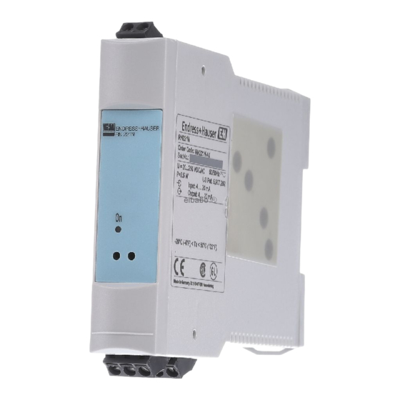
    "Secondary Master" in das Netzwerk eingefügt, unterbricht der RN221N ® automatisch seine HART -Kommunikation. Sobald der zusätzliche "Secondary Master" aus dem Netzwerk entfernt wird, setzt der RN221N seine Kommunikation fort. 3 Abmessungen Abb. 1: Abmessungen in mm (Angaben in Inches in Klammern)
  • Seite 8: Montage

    4 Montage Einbauhinweise ❑ Zulässige Umgebungstemperatur: -20 bis +50 °C ❑ Einbauort: Montage auf Hutschiene nach IEC 60715 ❑ Einbauhinweise: Vibrationsfreier Einbauort, Schutz vor Wärmeeinwirkung ❑ Einbaulage: keine Einschränkungen...
  • Seite 9: Verdrahtung Auf Einen Blick

    Relais 20...250 V DC/AC 50/60 Hz ® Abb. 2: Klemmenbelegung des RN221N mit HART Diagnose *) Der aktive Stromausgang muss immer beschaltet werden (wenn keine Auswertung des Ausgangsstroms erwünscht ist, kann eine Kurzschlussbrücke verwendet werden). " Achtung! In der Zuleitung in der Nähe des Gerätes (leicht erreichbar) muss ein als Trennvorrichtung gekennzeichneter Schalter sowie ein Überstromschutzor-...
  • Seite 10 Klemmenbelegung Ein- / Ausgang L für AC; + für DC Hilfsenergie N für AC; - für DC Klemmen für Relais Relais Reset Relais Eingang für Quittierung Status ® Messsignal + mit integriertem HART Messsignal Ausgangsseite (Non-Ex Bereich) Messsignal - Messsignal + Messsignal Eingangsseite (Ex-Bereich) (Anschluss Sensor) Messsignal -...
  • Seite 11: Inbetriebnahme

    6 Inbe- Belegung des DIP-Schalters triebnahme R = 250  R = 0  Relay Normally Closed Relay Normally Open Secondary Master Primary Master Bit 0 unmasked masked Bit 1 unmasked masked Bit 2 unmasked masked Bit 3 unmasked masked Bit 4 unmasked masked...
  • Seite 12 Einstellmöglichkeiten 1. Strommodus: Der RN221N wertet das Stromsignal in beiden Stromkreisen (Sensor und Auswertung) nach der NAMUR-Empfehlung NE-43 aus und steuert den Relaisausgang an, falls sich das Signal außerhalb des Messbereichs von 3,8 mA bis 20,5 mA befindet. Die NAMUR NE-43 definiert die Bereiche für die Ausfallsignalerkennung folgendermaßen:...
  • Seite 13 Bedeutung Bit 0 unmasked Primary variable out of limits Der Hauptmesswert des Messumformers liegt außerhalb der eingestellten Grenz- werte. Bit 1 unmasked Non-primary variable out of Mindestens ein zusätzlicher Messwert, limits der vom Messumformer geliefert wird, liegt außerhalb der eingestellten Grenze. Bit 2 unmasked Analog output saturated Das Ausgangssignal befindet sich außer-...
  • Seite 14 3. Auswertung des E+H-spezifischen Diagnosebefehls #231: Über diesen Diagnosebefehl wird der Gerätestatus anhand eines "Qua- lity-Code" mit vier Stufen dargestellt. Die Zuordnung eines bestimmten Gerätestatus zu einer entsprechenden Stufe im "Quality-Code" erfolgt im Messumformer. Weitere Informationen hierzu finden Sie in der Betriebsanleitung des verwendeten Messumformers.
  • Seite 15 Auswahl der Betriebsart Über den DIP-Schalter 10 kann bestimmt werden, ob der RN221N mit ® ® HART Diagnose die HART -Statusbytes oder den E+H-Diagnosebefehl #231 auswertet. Befinden sich die DIP-Schalter 4-9 alle in Position "OFF" (keine Maskierung eines Statusbits bzw. einer Stufe im "Quality-Code"), wird automatisch das 4-20 mA Signal für die Ausfallsignalerkennung verwendet,...
  • Seite 16: Wartung

    Steuereingang ’Reset Relais’: Führt ein Ereignis in der Messanordnung zur Aktivierung des Relais und der roten LED, bleibt der Zustand nach Wegfall des Ereignisses im RN221N gespeichert. Durch Brücken der beiden Klemmen, z.B. Rückstelltaster, wird die Meldung quittiert, die rote LED ausgeschaltet und das Relais deaktiviert, sobald das angeschlossene Gerät keinen Fehlerstatus mehr liefert.
  • Seite 17: Fehlerbehebung

    8 Fehler- behebung Modus Wirkung Ursache Fehlerbehebung entweder Ein- oder Aus- Verbindungen über- gangsstromkreis nicht prüfen geschlossen allgemein ’On’-LED leuchtet nicht Hilfsenergie nicht ange- Verbindungen über- schlossen prüfen ® Relais schaltet nicht bei Gerät in HART DIP-Schalter 4-9 auf ’off’ 4...20 mA Fehlerstrom, Kommu- Betriebsmodus...
  • Seite 18 Modus Wirkung Ursache Fehlerbehebung Gerät reagiert nicht auf Der Messumformer setzt Überprüfen Sie die den eingestellten Status das maskierte Bit nicht Zuordnung der Status- bits in der Betriebsanlei- tung des Messumformers ® Die HART -Kommu- Überprüfen Sie, ob sich ® nikation zum Mes- zusätzliche HART -Mas-...
  • Seite 19 Modus Wirkung Ursache Fehlerbehebung ® HART Gerät meldet einen Der angeschlossene Überprüfen Sie in der ® Betrieb Fehler, obwohl der Mes- HART -Messumformer Betriebsanleitung des sumformer keinen Fehler unterstützt den Befehl Messumformers, ob der liefert. DIP-Schalter 10 #231 nicht Befehl #231 unterstützt befindet sich in Stellung wird ®...
  • Seite 20: Technische Daten

    9 Technische Daten Eingangskenngrö- Anzahl ßen Speisespannung 16,7 V ± 0,2 V (bei I = 20 mA) Leerlaufspannung 26 V ± 5%  40 mA Kurzschlussstrom 328  Innenwiderstand Überbereich U/I-Diagramm Schleifenstrom (mA)
  • Seite 21 Eigensicherer Leerlaufspannung 27,3 V Eingang (Option) Kurzschlussstrom 87,6 mA Leistung 597 mW Kapazität 86 nF [EEx ia] IIC 683 nF [EEx ia] IIB, IIA 86 nF Group A, B 681 nF Group C 2278 nF Group D Induktivität 5,2 mH [EEx ia] IIC 18,9 mH [EEx ia] IIB, IIA 2,9 mH Group A, B 9,9 mH Group C...
  • Seite 22 Hilfsenergie Versorgungsspannung 20...250 V DC/AC, 50/60 Hz Leistungsaufnahme max. 5,0 W Stromaufnahme < 15 Elektrische Sicherheit Nach IEC 61 010-1, Schutzklasse I, Überspannungs- kategorie II, Verschmutzungsgrad 2, Überstrom- schutzorgan  10 A, Sicherung 500 mA T Galvanische Trennung zu allen anderen Stromkreisen Einsatz- Einbaubedingungen Vibrationsfreier Einbauort, Schutz vor Wärmeein-...
  • Seite 23 Konstruktiver Bauform/Abmessungen 110 x 22,5 x 112 mm (HxBxT) Gehäuse für Hut- Aufbau schiene nach IEC 60715 Gewicht ca.150g Werkstoffe Gehäuse: Kunststoff PC/ABS, UL 94V0 Anschlussklemmen • Codierte, steckbare Schraubklemme, Klemmbe- reich 2,5 mm² massiv, oder Litze mit Ade- rendhülse •...
  • Seite 24: Zubehör

    51002468 Schutzgehäuse IP66 zur Feldmontage 51004148 Aufklebe-Etikett bedruckt (max. 2x16 Zeichen) 51002393 Metall Schild für Tagnummer 11 Ergänzende • Technische Information RN221N (TI073R/09/de) • ATEX Sicherheitshinweise (XA005R/09/a3) Dokumenta- • Handbuch zur Funktionalen Sicherheit RN221N (SD008R/09/de) tion • Broschüre "Systemkomponenten (FA016K/09/de)
  • Seite 25 Table of contents 1 Safety instructions ..........26 2 Function .
  • Seite 26: Safety Instructions

    1 Safety instruc- Designated use ❑ Active barrier with power supply for safe separation of 4 to 20 mA current tions circuits with optional intrinsically safe input. The current transmitted from the passive transmitter to the input circuit (4 to 20 mA) is linearly trans- mitted to the output.
  • Seite 27 Safety icons Note! - leads to an indirect influence on the unit's operation or to an unforeseen reaction on the part of the device. " Caution! - leads to faulty operation or the destruction of the device. Warning! - leads to personal injury, safety hazards or the destruc- tion of the device.
  • Seite 28: Function

    ® RN221N can be selected as a HART primary or secondary master. The oper- ating mode of RN221N can be set on site by means of a DIP switch. ® Automatic switch-off of the HART master RN221N.
  • Seite 29: Dimensions

    If RN221N is working as the "secondary master" and if another "secondary ® master" is added to the network, RN221N automatically interrupts its HART communication. As soon as the additional "secondary master" is removed from the network, RN221N continues its communication.
  • Seite 30: Mounting

    4 Mounting Installation instructions ❑ Permitted ambient temperature: -20 to +50 °C ❑ Mounting location: Mounting on DIN rail as per IEC 60715 ❑ Installation instructions: Vibration-free mounting location, protect against external heating ❑ Orientation: No restrictions...
  • Seite 31: Quick Wiring Guide

    20...250 V DC/AC 50/60 Hz ® Fig. 2: Terminal assignment of RN221N with HART diagnosis *) The active current output must always be connected (if no evaluation of the output current is required, a jumper can be used). " Caution! A switch marked as a splitter and an overcurrent protector (rated current ...
  • Seite 32 Terminal assignment Input/output L for AC; + for DC Power supply N for AC; - for DC Terminals for relay Relay Reset relay Input for status acknowledgment Measuring signal + with integrated Measuring signal output side (non-Ex area) Measuring signal - Measuring signal + Measuring signal input side (Ex area) (sensor connection)
  • Seite 33: Commissioning

    6 Commission- Assignment of DIP switch R = 250  R = 0  Relay normally closed Relay normally open Secondary master Primary master Bit 0 unmasked masked Bit 1 unmasked masked Bit 2 unmasked masked Bit 3 unmasked masked Bit 4 unmasked masked...
  • Seite 34 Configuration options 1. Current mode: RN221N analyzes the current signal in both circuits (sen- sor and evaluation) in accordance with NAMUR Recommendation NE- 43 and triggers the relay output if the signal is outside the measuring range of 3.8 mA to 20.5 mA. NAMUR NE-43 defines the ranges for fail- ure signal detection as follows: •...
  • Seite 35 Meaning Bit 0 unmasked Primary variable out of limits The primary value of the transmitter is outside the set limit values. Bit 1 unmasked Non-primary variable out of lim- At least one additional measured value, supplied by the transmitter, is outside the set limit.
  • Seite 36 3. Evaluation of the E+H-specific diagnostic command #231: By means of this diagnostic code, the device status is displayed using a "quality code" with four stages. The assignment of a certain device status to a specific stage in the "quality code" takes place in the transmitter. More information on this can be found in the Operating Instructions of the transmitter used.
  • Seite 37 HART master to the communication jacks of RN221N. Primary/secondary master DIP switch 3 can be used to specify whether RN221N polls the transmitter as ® a primary or secondary master. This setting is important if another HART master, apart from RN221N, is in the network (e.g.
  • Seite 38: Maintenance

    If an event in the measuring arrangement activates the relay and the red LED, the status is saved in RN221N when the event has ceased. By jumpering the two terminals, e.g. reset switch, the message is acknowledged, the red LED switched off and the relay deactivated, as soon as the device connected no longer transmits an error status.
  • Seite 39: Fault Elimination

    8 Fault elimina- tion Mode Effect Cause Fault elimination Either the input circuit or Check connection output circuit is not closed 'On'-LED does not light General Power supply not con- Check connection nected ® Relay does not switch in Device in HART oper- Set DIP switches 4-9 to 4...20 mA...
  • Seite 40 Mode Effect Cause Fault elimination Device does not react to The transmitter does not Check the assignment of the set status set the masked bit the status bits in the Operating Instructions of the transmitter ® The HART communi- Check whether there are ®...
  • Seite 41 Mode Effect Cause Fault elimination ® ® HART Device reports an error The connected HART In the Operating Instruc- operation even though the trans- transmitter does not sup- tions of the transmitter, mitter does not return port command #231 check whether com- any error.
  • Seite 42: Technical Data

    9 Technical data Input Number Supply voltage 16.7 V ± 0.2 V (for I = 20 mA) Open-circuit voltage 26 V ± 5%  40 mA Short-circuit current 328  Internal resistance Overrange...
  • Seite 43 Intrinsically safe Open-circuit voltage 27.3 V input (option) Short-circuit current 87.6 mA Power 597 mW Capacitance 86 nF [EEx ia] IIC 683 nF [EEx ia] IIB, IIA 86 nF Group A, B 681 nF Group C 2278 nF Group D Inductance 5.2 mH [EEx ia] IIC 18.9 mH [EEx ia] IIB, IIA...
  • Seite 44 Power supply Supply voltage 20...250 V DC/AC, 50/60 Hz Power consumption Max. 5.0 W Current consumption < 15 Electrical safety To IEC 61 010-1, protection class I, overvoltage cat- egory II, pollution degree 2, overcurrent protection  10 A, fuse 500 mA T Galvanic isolation To all other circuits Operating condi-...
  • Seite 45 Mechanical con- Design/dimensions 110 x 22.5 x 112 mm (HxBxD) housing for DIN struction rail as per IEC 60715 Weight Approx.150g Materials Housing: plastic PC/ABS, UL 94V0 Terminals • Keyed, plug-on screw terminal, core size 2.5 mm² solid, or strands with ferrules •...
  • Seite 46: Accessories

    IP66 protective housing for field mounting 51004148 Printed adhesive label (max. 2x16 characters) 51002393 Metal sign for tag number 11 Documenta- • Technical Information RN221N (TI073R/09/en) • ATEX Safety Instructions (XA005R/09/a3) tion • Functional Safety Manual RN221N (SD008R/09/en) • "System Components" brochure (FA016K/09/en)
  • Seite 47 Índice de contenidos 1 Instrucciones de seguridad........48 2 Función .
  • Seite 48: Instrucciones De Seguridad

    1 Instrucciones Uso correcto del equipo ❑ Barrera activa con fuente de alimentación para el funcionamiento seguro de seguridad de circuitos de corriente de 4 a 20 mA, opcionalmente con entrada intrín- secamente segura. La corriente procedente del transmisor pasivo que pasa al circuito de entrada (4 a 20 mA) se transmite linealmente hacia la salida.
  • Seite 49 Iconos de seguridad Nota - repercute indirectamente sobre el funcionamiento del equipo o provoca una reacción imprevista por parte del mismo. " ¡Precaución! - causa un mal funcionamiento del equipo o incluso la destrucción de la misma. ¡Peligro! - causa lesiones personales, riesgos de seguridad o la des- trucción del equipo.
  • Seite 50: Función

    ® La RN221N puede definirse como equipo maestro HART primario o secun- dario. El modo de funcionamiento de la RN221N puede seleccionarse en campo mediante un microinterruptor. ® Desactivación automática del equipo maestro RN221N HART ®...
  • Seite 51: Dimensiones

    ® HART , entonces habrá que desactivar uno de los otros dos equipos maestros. Si la RN221N está funcionando como "equipo maestro secundario" y se añade otro "equipo maestro secundario" a la red, entonces la RN221N interrumpirá ® automáticamente su comunicación HART .
  • Seite 52: Montaje

    4 Montaje Instrucciones de instalación ❑ Temperaturas ambiente admisibles: -20 a +50 °C ❑ Lugar de instalación: montaje sobre raíl DIN según IEC 60715 ❑ Instrucciones para la instalación: lugar de instalación sin vibraciones, protegido contra calentamiento desde el exterior ❑...
  • Seite 53: Guía Rápida Para El Conexionado

    ® Fig. 2: Asignación de terminales de la RN221N con diagnóstico HART *) La salida de corriente activa tiene que encontrarse siempre conectada (si no se nece- sitase una evaluación de la salida de corriente, podría utilizarse entonces un puente de conexión).
  • Seite 54 Asignación de terminales Entrada/salida L para CA; + para CC Fuente de alimentación N para CA; - para CC Terminales para relé Relé Retroceso del relé Entrada para acuse de estado Señal de medida + con resistencia inte- Señal de medida en el lado de salida (zona no Ex) Señal de medida - Señal de medida +...
  • Seite 55: Puesta En Marcha

    6 Puesta en Asignación de microinterruptores marcha R = 250  R = 0  Relé normalmente cerrado Relé normalmente abierto Maestro secundario Maestro primario Bit 0 unmasked (sin enmascarar) masked (enmascarado) Bit 1 unmasked (sin enmascarar) masked (enmascarado) Bit 2 unmasked (sin enmascarar) masked (enmascarado) Bit 3...
  • Seite 56 Opciones de parametrización 1. Modo de corriente: la RN221N analiza la señal de corriente de los dos circuitos (sensor y evaluación) en conformidad con la recomendación NAMUR NE-43 y activa la salida de relé siempre que la señal se encuen- tre fuera del rango de medida de 3,8 mA a 20,5 mA.
  • Seite 57 Significado Bit 0 unmasked Primary variable out of limits El valor principal del transmisor está fuera (sin enmas- (Variable principal fuera de lími- de los límites establecidos. carar) tes) Bit 1 unmasked Non-primary variable out of Hay por lo menos un valor medido adi- (sin enmas- limits (Variable no principal cional, que proporciona el transmisor,...
  • Seite 58 3. Evaluación del comando de diagnóstico específico de E+H #231: Mediante este código de diagnóstico, se visualiza el estado del equipo utilizando un "código de calidad" de cuatro niveles. La asignación de un determinado estado del equipo a un nivel en el "código de calidad" se realiza en el transmisor.
  • Seite 59 Selección del modo de funcionamiento Se puede utilizar el microinterruptor 10 para seleccionar si la RN221N con ® ® diagnóstico HART ha de evaluar los bytes de estado HART o en cambio el comando de diagnóstico E+H #231. Si todos los microinterruptores 4-9 están en posición "OFF"...
  • Seite 60: Mantenimiento

    Si un evento en el sistema de medición activo el relé y el LED rojo, se guarda el estado en la RN221N cuando deja de existir el evento. Al puentear los dos terminales, p. ej., con el interruptor de reinicio, se confirma la recepción del mensaje, se apaga el LED rojo y se desactiva el relé...
  • Seite 61: Resolución De Fallos

    8 Resolución de fallos Modo Efecto Causa Resolución de fallos El circuito de entrada o Revise la conexión. el de salida no están cerrados. El LED 'On' no se General enciende Fuente de alimentación Revise la conexión. sin conectar El relé no conmuta en Equipo en modo de fun- Ponga los microinterrup- ®...
  • Seite 62 Modo Efecto Causa Resolución de fallos El equipo no responde al El transmisor no activa el Verifique las asignaciones estado establecido bit enmascarado de bits de estado indica- das en el manual de ins- trucciones del transmisor Se ha interrumpido la Compruebe si hay algún ®...
  • Seite 63 Modo Efecto Causa Resolución de fallos ® Modo El equipo señala un error El transmisor HART Consulte el manual de ® HART si bien el transmisor no que hay conectado no instrucciones del trans- comunica ningún error. soporta el comando #231 misor para ver si transmi- Microinterruptor 10 está...
  • Seite 64: Datos Técnicos

    9 Datos técnicos Entrada Número Tensión de alimentación 16,7 V ± 0,2 V (para I ≤20 mA) Tensión de circuito 26 V ± 5% abierto Corriente de cortocircuito  40 mA Resistencia interna 328 Sobrerrango Diagrama U/I Corriente de lazo (mA)
  • Seite 65 Entrada intrínseca- Tensión de circuito 27,3 V mente segura abierto (opción) Corriente de cortocircuito 87,6 mA Potencia 597 mW Capacidad 86 nF [EEx ia] IIC 683 nF [EEx ia] IIB, IIA 86 nF Grupos A, B 681 nF Grupo C 2278 nF Grupo D Inductancia 5,2 mH [EEx ia] IIC...
  • Seite 66 Salida de relé Tensión de conmutación a 250 Vca/ 30 Vcc (opción) Corriente máx. de conmutación hasta 3 A ca/cc Número de ciclos de conmutación 10 Aislamiento galvánico Con respecto a todos los demás circuitos Fuente de alimen- Tensión de alimentación 20...250 Vcc/Vca, 50/60 Hz tación Consumo de potencia...
  • Seite 67 Entorno Temperatura ambiente -20°C a +50°C Temperatura de almace- -20°C a +70°C namiento Clase de clima Según IEC 60654-1: clase B2 Grado de protección IP 20 Compatibilidad electro- Inmunidad a interferencias según IEC 61326, clase magnética (EMC) A (entorno industrial) Altura del lugar de instala- Según IEC 61010-1: <...
  • Seite 68 Interfaz de usuario LED 1 amarillo: "ON" - circuitos de entrada y salida están cerrados "OFF" - circuitos de entrada o/y salida no están cerrados -> circuito de cable abierto ® LED 2 amarillo: destella con cada intercambio de datos HART LED 3 rojo: se enciende cuando el equipo requiere mantenimiento Certificados Marca CE...
  • Seite 69: Accesorios

    Etiqueta adhesiva impresa (máx. 2x16 carac- teres) 51002393 Chapa metálica para número de etiqueta (TAG) 11 Documenta- • Información técnica RN221N (TI073R/09/en) • Instrucciones de seguridad ATEX (XA005R/09/a3) ción • Manual de seguridad funcional RN221N (SD008R/09/en) • Catálogo "Componentes de sistema" (FA016K/09/en)
  • Seite 72 www.endress.com/worldwide BA202R/09/es/13.10 FM9.0+SGML...

Inhaltsverzeichnis