Endress+Hauser RN221N Bedienungsanleitung
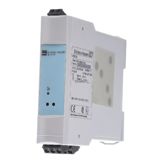
Speisetrenner
Vorschau ausblenden
Andere Handbücher für RN221N:
- Betriebsanleitung (76 Seiten) ,
- Bedienungsanleitung (72 Seiten) ,
- Handbuch (16 Seiten)

Verwandte Anleitungen für Endress+Hauser RN221N


Inhaltszusammenfassung für Endress+Hauser RN221N
- Seite 1 Compact Instructions RN221N de - Speisetrenner en - Active barrier fr - Alimentation 2 fils KA124R/09/a3/06.05 51003567...
-
Seite 3: Inhaltsverzeichnis
Speisetrenner Inhaltsverzeichnis 1 Sicherheitshinweise ..........4 2 Funktion . -
Seite 4: Sicherheitshinweise
1 Sicherheitshin- Bestimmungsgemäße Verwendung weise Speisetrenner mit Hilfsenergie zur sicheren Trennung von 4 bis 20 mA Normsignalstromkreisen mit optional eigensicherem Eingang. Der vom passiven Messumformer eingeprägte Strom im Eingangskreis (4 bis 20 mA) wird linear zum Ausgang übertragen. Das Gerät ist zur Montage auf Hutschiene nach IEC 60715 vorgesehen. - Seite 5 Sicherheitssymbole Wird das Gerät unsachgemäß oder nicht bestimmungsgemäß eingesetzt, kön- nen Gefahren von ihm ausgehen. Achten Sie deshalb in der Betriebsanleitung konsequent auf Sicherheitshinweise, die mit den folgenden Piktogrammen gekennzeichnet sind: Hinweis! - deutet auf Aktivitäten oder Vorgänge hin, die - wenn sie nicht ordnungsgemäß...
-
Seite 6: Funktion
2 Funktion Das Gerät dient der galvanischen Trennung und Speisung von 4 bis 20 mA Signalstromkreisen. Am Stromeingang werden Messumformer direkt ange- schlossen, ein zusätzliches Speisegerät ist nicht erforderlich. Das Stromsignal steht am Ausgang (aktiver Ausgang) zur weiteren Instrumentierung zur Ver- ®... -
Seite 7: Montage
4 Montage Einbauhinweise Zulässige Umgebungstemperatur: -20 bis +50 °C Einbauort: Montage auf Hutschiene nach IEC 60715 Einbauhinweise: Vibrationsfreier Einbauort, Schutz vor Wärmeeinwirkung Einbaulage: keine Einschränkungen 5 Verdrahtung Vergleichen Sie vor Inbetriebnahme die Übereinstimmung der Versorgungs- auf einen Blick spannung mit den Angaben auf dem Typenschild. Achtung! In der Zuleitung in der Nähe des Gerätes (leicht erreichbar) muss ein als Trennvorrichtung gekennzeichneter Schalter, sowie ein Überstromschutzor-... - Seite 8 Klemmenbelegung Abb. 2: Klemmenbelegung Eingang - Anschluss Sensor Die Versorgung von passiven Messumformern erfordert keine weiteren Kom- ponenten. Ist bei langen Signalleitungen mit energiereichen Transienten zurechnen, empfehlen wir einen Überspannungsschutz. Ausgang - Anschluss Auswerteeinheit Bei Einschleifung des Kommunikationswiderstandes in die Stromschleife ist- der Spannungsabfall zuberücksichtigen!
-
Seite 9: Wartung
Terminal layout In- / Output L für AC; + für DC N für AC; - für DC Hilfsenergie Schutzleiter (PE) Messsignal + Messsignal Ausgangsseite (Non-Ex Messsignal - Bereich) ® Messsignal + mit integriertem HART Kommunikationswiderstand (250 Ω) Messsignal + Messsignal Eingangsseite (Ex-Bereich) Messsignal - ®... -
Seite 10: Technische Daten
7 Technische Das Gerät stellt eine galvanische Trennung zwischen allen Stromkreisen Daten sicher. Eingangskenn- Speisespannung, nominal 16,7 V ± 0,2 V (bei I = 20mA) größen U/I-Diagramm Schleifenstrom (mA) Ausgang 4...20 mA Anzahl Leerlaufspannung 24 V ± 10% Überbereich 0...700 Ω (ohne Kommunikationswiderstand Bürde (Lastwiderstand) Klemme O+... - Seite 11 Hilfsenergie Versorgungsspannung 20...250 V DC/AC, 50/60 Hz Leistungsaufnahme max. 2,5 W Stromaufnahme < 15 Elektrische Sicherheit Nach IEC 61010-1, Schutzklasse I, Überspan- nungskategorie II, Verschmutzungsgrad 2, Installa- tionsseitiges Überstromschutzorgan ≤ 10 Messgenauigkeit Referenzbedingungen Kalibriertemperatur bei 25 °C, ± 5 K ≤...
- Seite 12 Konstruktiver Auf- Bauform/Abmessungen 110 x 22,5 x 112 mm (HxBxT) Gehäuse für Hut- schiene nach IEC 60715 Gewicht ca. 150g Werkstoffe Gehäuse: Kunststoff PC/ABS, UL 94V0 Anschlussklemmen • Codierte, steckbare Schraubklemme, Klemmbe- reich 2,5 mm² massiv, oder Litze mit Aderend- hülse •...
-
Seite 13: Ergänzende Dokumentation
8 Ergänzende • Technische Information (TI073R09de) • ATEX Sicherheitshinweise (XA005R09a3) Dokumenta- • Broschüre "Systemkomponenten" (FA016K09de) tion • Handbuch zur Funktionalen Sicherheit (SD008R09de)