Bender ISOMETER isoRW425 Installationsanleitung
Vorschau ausblenden
Andere Handbücher für ISOMETER isoRW425:
- Handbuch (72 Seiten) ,
- Kurzanleitung (41 Seiten) ,
- Kurzanleitung (13 Seiten)
Inhaltsverzeichnis
Quicklinks
ISOMETER® isoRW425
Isolationsüberwachungsgerät für ungeerdete
AC, AC/DC- und DC-Stromversorgungen (IT-Systeme)
für Bahn-Applikationen bis 3(N)AC, AC/DC 440 V
Insulation monitoring device for unearthed
IT AC-, AC/DC and DC systems (IT systems)
for railway applications up to 3(N)AC, AC/DC 440 V
isoRW425_D00052_05_Q_DEEN / 04.2021
Quickstart DE/EN
Inhaltsverzeichnis

Verwandte Anleitungen für Bender ISOMETER isoRW425


Inhaltszusammenfassung für Bender ISOMETER isoRW425
- Seite 1 ISOMETER® isoRW425 Isolationsüberwachungsgerät für ungeerdete AC, AC/DC- und DC-Stromversorgungen (IT-Systeme) für Bahn-Applikationen bis 3(N)AC, AC/DC 440 V Insulation monitoring device for unearthed IT AC-, AC/DC and DC systems (IT systems) for railway applications up to 3(N)AC, AC/DC 440 V isoRW425_D00052_05_Q_DEEN / 04.2021 Quickstart DE/EN...
-
Seite 2: Ordering Information
Bestandteil der Gerätedokumentation sind neben Part of the device documentation in addition to dieser Kurzanleitung die „Sicherheitshinweise für this quickstart is the enclosed “Safety instructions Bender-Produkte“ dazugehörige for Bender products“ and the manual, which can Handbuch, herunterladbar unter be downloaded from https://www.bender.de/en/ https://www.bender.de/service-support/down- service-support/downloads. -
Seite 3: Montage
ISOMETER® isoRW425 Abmessungen Dimensions Alle Maße in mm All dimensions in mm Montage Mounting Click & Click! Variante A / Option A: Variante B / Option B: Montage auf Hutschiene / DIN rail mounting Schraubbefestigung / Screw mounting isoRW425_D00052_05_Q_DEEN / 04.2021... -
Seite 4: Wiring Diagram
ISOMETER® isoRW425 Anschlussbild Wiring diagram L1/+ L2/- L1/+ Test / Reset MENU COM465IP RS-485 Legende Legend Klemme/ Anschlüsse Connections Terminal Anschluss an die Versorgungsspannung U über Connection to the supply voltage U via a fuse: A1, A2 Schmelzsicherung: If supplied from an IT system, both lines have to be protected by a Bei Versorgung aus IT-System beide Leitungen absichern.* fuse.* Jede Klemme jeweils separat an PE anschließen:... -
Seite 5: Menü-Übersicht
ISOMETER® isoRW425 Menü-Übersicht Menu overview Messwertanzeige Menüauswahl Parametereingabe Measurement display Menu selection Parameter selection > < 1.5 s > > . . . 1.5 s 1.5 s < t > 5 Min. < > 1.5 s Z [kΩ] R [kΩ] C [µF] U L1 L2 [V ] <... -
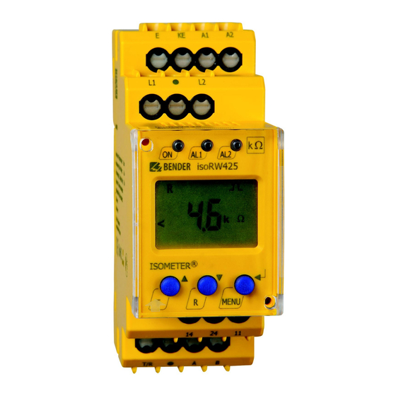
Seite 6: Display Elements
ISOMETER® isoRW425 Display-Elemente Display elements Funktion Gerätefront/ Device front Function grün - On green - On gelb - Alarm yellow - Alarm gelb - Alarm yellow - Alarm Aufwärts-Taste Up button Test-Taste (> 1,5 s drücken) Test button (press > 1.5 s) Bei gedrückter Test-Taste werden die By pressing and holding the test Display-Elemente angezeigt. - Seite 7 ISOMETER® isoRW425 Inbetriebnahme Commissioning 1. Prüfen auf korrekten Anschluss des ISOMETER®s an 1. Check that the ISOMETER® is properly connected to das zu überwachende Netz. the system to be monitored. 2. Versorgungsspannung U für ISOMETER® zuschal- 2. Connect the supply voltage U to the ISOMETER®.
-
Seite 8: Error Codes
If the error continues to exist after checking the device Fehler weiterhin auftritt, liegt ein Fehler im Gerät vor. connections, there is an error inside the device. E.xx Gerätefehler - Kontakt zum Bender-Service aufnehmen. Device error - Contact Bender Service isoRW425_D00052_05_Q_DEEN / 04.2021... -
Seite 9: Supply Voltage
ISOMETER® isoRW425 Technische Daten Technical data ()* = Werkseinstellung ()* = Factory settings Isolationskoordination nach IEC 60664-1/ Insulation coordination acc. to IEC 60664-1/ IEC 60664-3 IEC 60664-3 Bemessungsspannung ..............440 V Rated voltage ................440 V Überspannungskategorie ..............III Overvoltage category ..............III Versorgungsspannung Supply voltage Versorgungsspannung U ....AC 100…240 V/DC 24…240 V... - Seite 10 ISOMETER® isoRW425 Schnittstelle Interface Schnittstelle/Protokoll ....RS-485/BMS, Modbus RTU, isoData Interface/protocol .......RS-485/BMS, Modbus RTU, isoData Baudrate .................... Baud rate ................... ..BMS (9,6 kBit/s), Modbus RTU (einstellbar), isoData (115,2 kBits/s) .. BMS (9.6 kBit/s), Modbus RTU (selectable), isoData (115.2 kBits/s) Leitungslänge (9,6 kBits/s) ..........≤ 1 200 m Cable length (9.6 kBits/s)..........≤...
-
Seite 11: Normen, Zulassungen Und Zertifizierungen
ISOMETER® isoRW425 Normen, Zulassungen und Zertifizierungen Standards, approvals and certifications Das ISOMETER® wurde unter Beachtung folgender The ISOMETER® has been developed in compliance with Normen entwickelt: the following standards: • DIN EN 61557-8 (VDE 0413-8): 2015-12/ • DIN EN 61557-8 (VDE 0413-8): 2015-12/ Ber1: 2016-12 Ber1: 2016-12 •... - Seite 12 Nachdruck und Vervielfältigung Reprinting and duplicating nur mit Genehmigung des Herausgebers. only with permission of the publisher. Bender GmbH & Co. KG Bender GmbH & Co. KG Postfach 1161 • 35301 Grünberg • Deutschland PO Box 1161 • 35301 Grünberg • Germany Londorfer Str.