Denon DN-X300 Bedienungsanleitung
Inhaltsverzeichnis
Verfügbare Sprachen
Verfügbare Sprachen
Quicklinks
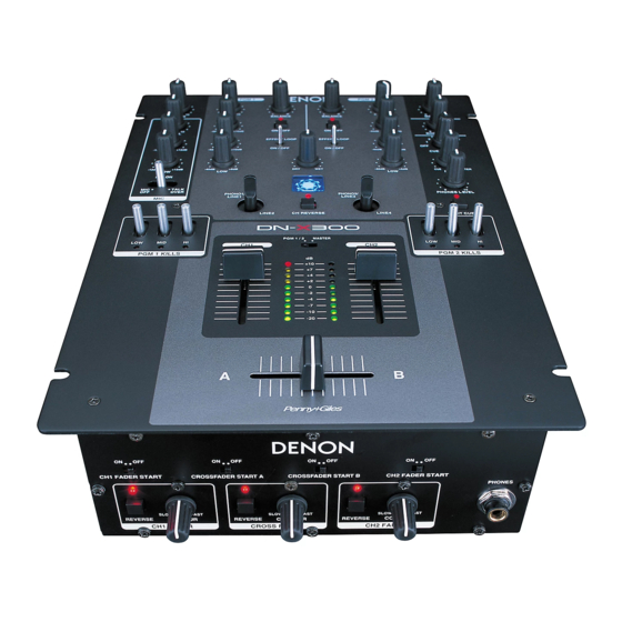
DJ MIXER / DJ 混音台
DN-X300
OPERATING INSTRUCTIONS
BEDIENUNGSANLEITUNG
MODE D'EMPLOI
ISTRUZIONI PER L'USO
INSTRUCCIONES DE OPERACION
GEBRUIKSAANWIJZING
BRUKSANVISNING
操作說明書
FOR ENGLISH READERS
PAGE
5 ~ PAGE
FÜR DEUTSCHE LESER
SEITE
11 ~ SEITE
POUR LES LECTEURS FRANCAIS
PAGE
17 ~ PAGE
PER IL LETTORE ITALIANO
PAGINA 23 ~ PAGINA 28
PARA LECTORES DE ESPAÑOL
PAGINA 29 ~ PAGINA 34
VOOR NEDERLANDSTALIGE LEZERS
PAGINA 35 ~ PAGINA 40
FOR SVENSKA LÄSARE
SIDA
41 ~ SIDA
中
文
第 47 頁
10
16
22
46
~
第 53 頁
Kapitel
Inhaltsverzeichnis

Verwandte Anleitungen für Denon DN-X300


Inhaltszusammenfassung für Denon DN-X300
-
Seite 1: Operating Instructions
DJ MIXER / DJ 混音台 DN-X300 OPERATING INSTRUCTIONS INSTRUCCIONES DE OPERACION BEDIENUNGSANLEITUNG GEBRUIKSAANWIJZING MODE D’EMPLOI BRUKSANVISNING 操作說明書 ISTRUZIONI PER L’USO FOR ENGLISH READERS PAGE 5 ~ PAGE FÜR DEUTSCHE LESER SEITE 11 ~ SEITE POUR LES LECTEURS FRANCAIS PAGE 17 ~ PAGE... -
Seite 11: Hauptmerkmale
Wir danken Ihnen sehr für den Kauf des DENON DN-X300 DJ MIXER. (Beziehen Sie sich auf Seite 3.) DENON ist stolz darauf, Audio-Freunden und Musikliebhabern diesen erweiterten DJ MIXER als einen weiteren Beweis der kompromisslosen Bestrebungen von DENON nach Erreichen der ultimativen Klangqualität zu präsentieren. - Seite 12 DEUTSCH SPLIT CUE-Taste (2) Hinteres anschlussfeld (3) Vorderes Bedienfeld • Im STEREO-Modus wird der Stereosound von MASTER und CUE in beide Ohrenkappen Netzbetriebschalter (POWER) PHONO1, 2 / LINE1, 3-Schalter CH 1/2 FADER START-Schalter eingespeist. Im SPLIT CUE-Modus liefert der • Zur Auswahl der Stromversorgung “ON” oder •...
-
Seite 13: Verbindungen
Stellen Sie sicher, dass alle Fader auf Null stehen und diese Einheit abgeschaltet ist. Achten Sie darauf, immer Kabel gleicheitig anzuschließen und beachten Sie die L- und R- Position der Buchsen an dem DN-X300 und an den externen Geräte. 5. Verbinden Stereoausgänge Endverstärkern, Tapedecks, MD-Recordern und/oder CD-Recordern. -
Seite 14: Technische Daten
DEUTSCH • Mik-Send-Ausgang: 1 Mono Spitze der 1/4” TRS-Buchsen TECHNISCHE DATEN Ausgangsimpedanz 1 kΩ/kOhm Pegel –14 dBV (200 mVrms) (10 kΩ/kOhm-Last) • Phono-Eingänge: 2 Stereo Asymmetrische Cinchbuchsen Eingangsimpedanz 50 kΩ/kOhm • Kopfhörer-Ausgang: Stereo 33 Ω/Ohm Pegel –50 dBV (3 mV) Ausgangsimpedanz (32 Ω/Ohm-Last) Pegel... -
Seite 15: Fader-Start
$1 zur Steuerung der FADER FADER FADER FADER Verwenden Sie die PGM1 PGM2 Channel-Fader-Startup- CROSSFADER DN-X300 CD-Player (DN-S3000) CD-Player (DN-S3000) Kurve. CONTOUR -Regler $3 für die Steuerung der Startkurve. Wenn Sie den Player starten wollen, schieben Sie den Channel-Fader @1 nach oben... -
Seite 16: Drehen Der Eingangswahlschalter
DEUTSCH DREHEN DER EINGANGSWAHLSCHALTER Wissenswertes über Kabel 1. Trennen Sie das Netzkabel ab. (Für RCA-Eingangs-/Ausgangsbuchse) 2. Entfernen Sie die Knöpfe vom oberen Bedienfeld. RCA-Pin-Stecker 3. Entfernen Sie die 6 Schrauben zur Befestigung des Kabel 1 Asymmetrisch oberen Bedienfeldes. 4. Entfernen Sie die 2 Schrauben zur Befestigung der Schaltereinheit.