Inhaltsverzeichnis

Verwandte Anleitungen für AFRISO WaterControl 01.1


Inhaltszusammenfassung für AFRISO WaterControl 01.1
- Seite 1 Betriebsanleitung Funkgesteuertes Wasserventil WaterControl 01.1 Typ: G1 Typ: G¾ Typ: G1¼ Typ: G1½ Copyright 2021 AFRISO-EURO-INDEX GmbH. Alle Rechte vorbehalten. Version: 02.2021.0 ID: 900.000.0944...
- Seite 2 Über diese Betriebsanleitung Über diese Betriebsanleitung Diese Betriebsanleitung beschreibt das Funkgesteuerte Wasserventil WaterControl 01.1 (im Folgenden auch „Produkt“). Diese Betriebsanleitung ist Teil des Produkts. • Sie dürfen das Produkt erst benutzen, wenn Sie die Betriebsanleitung vollständig gelesen und verstanden haben.
-
Seite 3: Warnhinweise Und Gefahrenklassen
Sie alle im Zusammenhang mit diesem Warnsymbol beschriebenen Hinweise, um Unfälle mit Todesfolge, Verlet- zungen und Sachschäden zu vermeiden. Dieses Symbol warnt vor gefährlicher elektrischer Span- nung. Wenn dieses Symbol in einem Warnhinweis gezeigt wird, besteht die Gefahr eines elektrischen Schlags. WaterControl 01.1... -
Seite 4: Informationen Zur Sicherheit
Führen Sie bei der Verwendung des Produkts alle Arbeiten ausschließlich unter den in der Betriebsanleitung und auf dem Typenschild spezifizierten Bedingungen und innerhalb der spezifizierten technischen Daten und in Übereinstimmung mit allen am Einsatzort geltenden Bestimmungen, Normen und Sicherheitsvorschriften durch. WaterControl 01.1... -
Seite 5: Vorhersehbare Fehlanwendung
Verbinden des Produkts mit EnOcean-Produkten Verbinden von EnOcean-Produkten darf nur von einer Fachkraft mit geeig- neter fachlicher Ausbildung, Kenntnissen und Erfahrung vorgenommen wer- den, die Gefahren erkennen und vermeiden kann, die von der Elektrizität ausgehen können. WaterControl 01.1... -
Seite 6: Persönliche Schutzausrüstung
Gefährdungen auftreten können, die nicht direkt vom Produkt ausge- hen. Veränderungen am Produkt Führen Sie ausschließlich solche Arbeiten an und mit dem Produkt durch, die in dieser Betriebsanleitung beschrieben sind. Nehmen Sie keine Verände- rungen vor, die in dieser Betriebsanleitung nicht beschrieben sind. WaterControl 01.1... -
Seite 7: Transport Und Lagerung
Benutzen Sie für den Transport die Originalverpackung. • Lagern Sie das Produkt nur in trockener, sauberer Umgebung. • Stellen Sie sicher, dass das Produkt bei Transport und Lagerung stoßge- schützt ist. Nichtbeachtung dieser Anweisungen kann zu Sachschäden führen. WaterControl 01.1... -
Seite 8: Übersicht Motorbetriebener Absperrkugelhahn
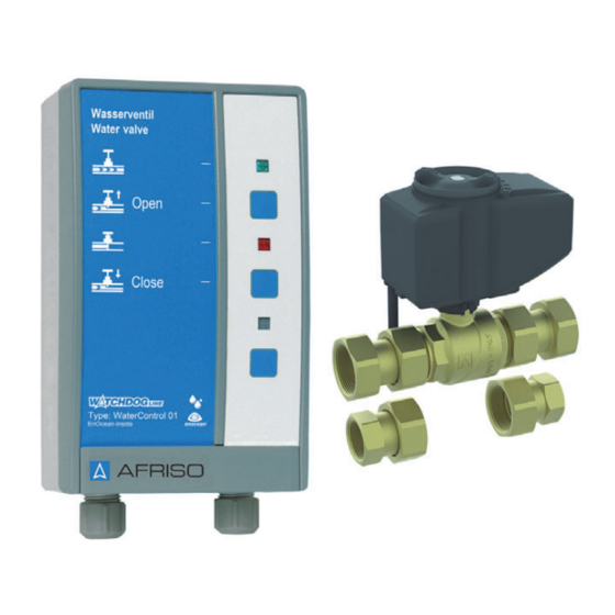
Motorantrieb mit Handrad für den manuellen Betrieb. Das Signalteil ist mit einem EnOcean®-Funkmodul ausgestattet. Übersicht motorbetriebener Absperrkugelhahn A. Motorantrieb D. Verschraubung G1i B. Handrad zum manuellen Betrieb E. Verschraubung G¾i C. Arretierclip (zum Lösen des Motors F. Messingkugelhahn G1 vom Kugelhahn) WaterControl 01.1... -
Seite 9: Produktbeschreibung
C. Taste: „Open“ D. Rote LED: Absperrkugel- hahn geschlossen E. Taste: „Close“ F. Ohne Funktion G. Ohne Funktion H. Icon aus der AFRISO- home App (in Verbindung mit dem Gateway) I. Typbezeichnung des Pro- dukts Abbildung 1: Signalteil WaterControl 01.1... - Seite 10 Taste Mit dieser Taste wird das Öffnen des Absperrkugel- hahns ausgelöst. Anzeige Absperrkugelhahn geschlossen. Die rote LED rechts neben dem Symbol signalisiert, dass der Absperrkugelhahn geschlossen ist. Taste Mit dieser Taste wird das Schließen des Absperrku- gelhahns ausgelöst. WaterControl 01.1...
- Seite 11 Produktbeschreibung Abmessungen 65 mm 100 mm 60 mm Abbildung 2: Abmessungen Signalteil WaterControl 01.1...
- Seite 12 Produktbeschreibung 108 mm G¾ 143 mm 156 mm Abbildung 3: Abmessungen Absperrkugelhahn G1 mit Verschraubungen G¾ und G1 WaterControl 01.1...
- Seite 13 Produktbeschreibung 108 mm G1¼ G1½ 184 mm Abbildung 4: Abmessungen Absperrkugelhahn G1½ mit Verschraubungen G1¼ und G1½ WaterControl 01.1...
- Seite 14 Wasserleitung ab. Über das AFRISOhome Gateway können automatisiert Meldungen verschickt werden, wenn der Absperrkugelhahn seinen Zustand geändert hat. Zulassungsdokumente, Bescheinigungen, Erklärungen Das Produkt entspricht: • EMV-Richtlinie (2014/30/EU) • Niederspannungsrichtlinie (2014/35/EU) • Radio Equipment Directive, RED (2014/53/EU) • RoHS-Richtlinie (2011/65/EU) WaterControl 01.1...
- Seite 15 Nennleistung Stehender Motor < 2 VA Laufender Motor < 5 VA Schutzklasse (EN 60730) Schutzart (EN 60529) IP 40 Anbringungsart fest angeschlossener Typ M Leitungen (EN 60730-1) Wirkungsweise Typ 1 Verschmutzungsgrad (EN 60730-1) PD II Bemessungs-Stoßspannung 2500 V WaterControl 01.1...
- Seite 16 Länge Verbindungskabel Umgebungsbedingungen Umgebungstemperatur Betrieb 0 ... 50 °C Umgebungstemperatur Lagerung -20 ... 70 °C Umgebungstemperatur Medium 4 ... 80 °C Relative Luftfeuchtigkeit 80 % Elektrische Daten Versorgungsspannung DC 24 V Schutzklasse (EN 60730) Schutzart (EN 60529) IP 40 WaterControl 01.1...
-
Seite 17: Montage
Wasserleitung entleert ist, bevor Sie den Absperrku- gelhahn montieren. Signalteil montieren Stellen Sie sicher, dass das Signalteil in Innenräumen an eine ebene, feste und trockene Wand montiert wird. Stellen Sie sicher, dass das Signalteil jederzeit zugänglich und einsehbar ist. WaterControl 01.1... - Seite 18 Stellen Sie sicher, dass das Signalteil vor Wasser und Spritzwasser geschützt ist. 1. Befestigen Sie die Schraube an der Wand. 2. Hängen Sie das Signalteil ein. 3. Befestigen Sie das Signal- teil an der Wand mit einer Schraube an der unteren Lasche. WaterControl 01.1...
- Seite 19 Wenn der Motor bei der Montage hindert, können Sie ihn vorübergehend vom Messingkugelhahn abbauen: 1. Schieben Sie den Halte- clip (A) auf die Stellung „Schloss offen“. 2. Nehmen Sie den Motor 3. Montieren Sie den Mess- ingkugelhahn. 4. Stecken Sie den Motor auf den Messingkugelhahn. WaterControl 01.1...
- Seite 20 2. Ziehen Sie die Verschraubungen mit dem angegebenen Anzugsmoment - G¾ und G1 = 60 Nm - G1¼ und G1½ = 80 Nm 3. Öffnen Sie die Absperrarmatur für die Leitung wieder. 4. Prüfen Sie die Leitung auf Dichtheit. WaterControl 01.1...
- Seite 21 Der Absperrkugelhahn ist fest am Signalteil angeschlossen. Das Verbin- dungskabel zwischen Signalteil und Absperrkugelhahn darf nicht verlängert oder gekürzt werden. Das Signalteil hat ein fest angeschlossenes Netzkabel mit Flachstecker. 1. Stecken Sie den Netzstecker des Signalteils in eine geeignete Schutzkon- takt-Steckdose ein. WaterControl 01.1...
-
Seite 22: Produkt Mit Einzulernenden Geräten Verbinden
Stellen Sie sicher, dass die Netzspannung unterbrochen ist. Für den Einlernvorgang werden am Produkt nur die beiden Tasten LRNMOD (A) und LRNTEL (B) auf der Platine es Signalteils benötigt. 1. Beachten Sie die Abbildung “Platine des Signalteils” auf Seite 23. WaterControl 01.1... - Seite 23 Inbetriebnahme A. LRNMOD-Taste B. LRNTEL-Taste C. Rote LED D. EnOcean-Funkmodul E. Trennbarriere F. Anschlussbereich 24 V DC G. Anschlussbereich 230 V AC H. Transformator Abbildung 5: Platine des Signalteils WaterControl 01.1...
- Seite 24 2. Verbinden Sie das einzu- lernende Gerät mit dem Produkt. Stellen Sie beim Schlie- ßen des Signalteils Fol- gendes sicher: - Die Antenne des EnO- cean-Funkmoduls muss auf der rechten Seite entlang der Gehäuse- wand in die Führungen (A) geklemmt sein. WaterControl 01.1...
- Seite 25 Inbetriebnahme 3. Schließen Sie das Signal- teil nach Beendigung des Verbindungsvorgangs. WaterControl 01.1...
- Seite 26 1. Schalten Sie die Netzspannung ein. 2. Drücken Sie die LRNTEL-Taste (B) auf der Platine des Signalteils. 3. Das Signalteil sendet ein Lern-Telegramm an das AFRISOhome Gate- way. - Das AFRISOhome Gateway ist mit dem Signalteil verbunden. WaterControl 01.1...
- Seite 27 Stellen Sie sicher, dass das Produkt ordnungsgemäß montiert und elekt- risch angeschlossen wurde. 1. Stecken Sie den Netzstecker des Signalteil in eine geeignete Schutzkon- takt-Steckdose ein. - Die grüne LED leuchtet, wenn der Absperrkugelhahn geöffnet ist. - Die rot LED leuchtet, wenn der Absperrkugelhahn geschlossen ist. WaterControl 01.1...
-
Seite 28: Betrieb
Wasserleitung ab und die rote LED am Signalteil leuchtet. Das Signalteil verschickt eine Meldung an das AFRISOhome Gateway, wenn der Absperr- kugelhahn seinen Zustand geändert hat. Über die AFRISO App erhält der Endanwender eine Meldung, dass Wasser detektiert wurde. - Seite 29 Absperrkugelhahn über Signalteil öffnen/schließen 1. Halten Sie die mittlere Taste (Close) gedrückt, bis die rote LED leuchtet. - Der Absperrkugelhahn ist geschlossen. 2. Halten Sie die obere Taste (Open) gedrückt, bis die grüne LED leuch- tet. - Der Absperrkugelhahn ist geöffnet. WaterControl 01.1...
-
Seite 30: Absperrkugelhahn Mit Funk-Flächentaster Öffnen/Schließen
Absperrkugelhahn mit Funk-Flächentaster öffnen/schließen Mit dem Funk-Flächentaster kann der Absperrkugelhahn geöffnet oder geschlossen werden. 7.4.1 Funktionsprüfung mit Funk-Flächentaster 1. Drücken Sie die Wippe am Funk-Flächentaster. - Der Absperrkugelhahn öffnet oder schließt die Wasserzufuhr. - Am Signalteil leuchtet die entsprechende LED. WaterControl 01.1... -
Seite 31: Wartung
LEDs leuchten nicht Keine Versorgungs- Stellen Sie die Versor- spannung gungsspannung her Absperrkugelhahn ist Schließen oder öffnen nicht vollständig geöff- Sie den Absperrkugel- net oder geschlossen hahn vollständig Sonstige Störungen Bitte wenden Sie sich an die AFRISO-Service Hotline WaterControl 01.1... -
Seite 32: Außerbetriebnahme Und Entsorgung
3. Entsorgen Sie das Produkt. Rücksendung Vor einer Rücksendung Ihres Produkts müssen Sie sich mit uns in Verbin- dung setzen (service@afriso.de). Gewährleistung Informationen zur Gewährleistung finden Sie in unseren Allgemeinen Geschäftsbedingungen im Internet unter www.afriso.com oder in Ihrem Kauf- vertrag. WaterControl 01.1... -
Seite 33: Ersatzteile Und Zubehör
Verwenden Sie nur Original Ersatz- und Zubehörteile des Herstellers. Nichtbeachtung dieser Anweisung kann zu Sachschäden führen. Produkt Artikelbezeichnung Art.-Nr. Abbildung Funkgesteuertes Wasserventil 42570 WaterControl 01.1 G¾ Funkgesteuertes Wasserventil 42571 WaterControl 01.1 G1 Ersatzteile und Zubehör Artikelbezeichnung Art.-Nr. Abbildung Absperrkugelhahn 24 V G¾ + G1 42574 WaterControl 01.1... - Seite 34 Sie auf www.enocean.com. • Funkstandard • Funktechnologie • AN001 • AN102 • AN103 • AN201 14.3 Möglichkeiten der EnOcean®-Technologie Unterlagen über EnOcean®-Technologien finden Sie im Internet unter www.afrisohome.de. Auf unserem YouTube-Channel finden Sie eine Reihe von Videos zu AFRISO-Produkten. WaterControl 01.1...
- Seite 35 Operating instructions Radio-controlled water valve WaterControl 01.1 Type: G1 Type: G¾ Type: G1¼ Type: G1½ Copyright 2021 AFRISO-EURO-INDEX GmbH. All rights reserved. Version: 02.2021.0 ID: 900.000.0944...
- Seite 36 About these operating instructions About these operating instructions These operating instructions describe the radio-controlled water valve WaterControl 01.1 (also referred to as "product" in these operating instruc- tions). These operating instructions are part of the product. • You may only use the product if you have fully read and understood these operating instructions.
- Seite 37 This symbol alerts to hazardous electrical voltage. If this symbol is used in a safety message, there is a hazard of electric shock. WaterControl 01.1...
-
Seite 38: Information On Safety
WaterControl 01.1... -
Seite 39: Qualification Of Personnel
Connecting the product to EnOcean® products Only skilled persons with relevant education and experience to enable him or her to perceive risks and to avoid hazards which electricity can create may connect EnOcean® products. WaterControl 01.1... - Seite 40 Modifications to the product Only perform work on and with the product which is explicitly described in these operating instructions. Do not make any modifications to the product which are not described in these operating instructions. WaterControl 01.1...
-
Seite 41: Transport And Storage
Use the original packaging when transporting the product. • Store the product in a clean and dry environment. • Verify that the product is protected against shocks and impact during trans- port and storage. Failure to follow these instructions can result in equipment damage. WaterControl 01.1... - Seite 42 Overview motor-driven shut-off ball valve A. Motor drive D. Screw connection G1 female B. Hand wheel for manual operation E. Screw connection G¾ female C. Locking clip (for releasing the motor F. Brass ball valve G1 from the ball valve) WaterControl 01.1...
-
Seite 43: Product Description
C. Key: "Open" D. Red LED: Shut-off ball valve closed E. Key: "Close" F. Without function G. Without function H. Icon from AFRISOhome App (in conjunction with gateway) I. Type designation of the product Fig. 1: Control unit WaterControl 01.1... - Seite 44 This key triggers opening of the shut-off ball valve. Indication Shut-off ball valve closed. The red LED to the right of the symbol indicates that shut-off ball valve is closed. This key triggers closing of the shut-off ball valve. WaterControl 01.1...
- Seite 45 Product description Dimensions 65 mm 100 mm 60 mm Fig. 2: Dimensions control unit WaterControl 01.1...
- Seite 46 Product description 108 mm G¾ 143 mm 156 mm Fig. 3: Dimensions shut-off ball valve G1 with screw connections G¾ and G1 WaterControl 01.1...
- Seite 47 Product description 108 mm G1¼ G1½ 184 mm Fig. 4: Dimensions shut-off ball valve G1½ with screw connections G1¼ and G1½ WaterControl 01.1...
- Seite 48 The AFRISOhome gateway allows for automatic transmission of messages when the shut-off ball valve has changed its state. Approvals, conformities, certifications The product complies with: • EMC Directive (2014/30/EU) • Low Voltage Directive (2014/35/EU) • Radio Equipment Directive, RED (2014/53/EU) • RoHS Directive (2011/65/EU) WaterControl 01.1...
- Seite 49 Motor running < 5 VA Protection class (EN 60730) Degree of protection (EN 60529) IP 40 Type of attachment of non-detachable Type M cord (EN 60730-1) Type of action Type 1 Pollution degree (EN 60730-1) PD II Rated impulse voltage 2500 V WaterControl 01.1...
- Seite 50 0 ... 50 °C Ambient temperature storage -20 ... 70 °C Ambient temperature medium 4 ... 80 °C Relative humidity 80 % Electrical data Supply voltage DC 24 V Protection class (EN 60730) Degree of protection (EN 60529) IP 40 WaterControl 01.1...
- Seite 51 Verify that the control unit is protected against water and splash water. 1. Mount the screw to the wall. 2. Fit the control unit. 3. Fasten the control unit by screwing the bottom lug to the wall. WaterControl 01.1...
- Seite 52 1. Push the locking clip (A) to the position "lock open". 2. Remove the motor. 3. Mount the brass shut-off ball valve. 4. Fit the motor to the brass shut-off ball valve. WaterControl 01.1...
- Seite 53 2. Tighten the screw connections with the specified tightening torque: - G¾ and G1 = 60 Nm - G1¼ and G1½ = 80 Nm 3. Open the shut-off fitting for the water pipe. 4. Verify tightness of the pipe. WaterControl 01.1...
- Seite 54 The control unit has a permanently connected mains cable with flat connec- tor. 1. Plug the control unit into a suitable isolated, earthed power outlet. WaterControl 01.1...
- Seite 55 Verify that the mains voltage has been interrupted. The two keys LRNMOD (A) and LRNTEL (B) on the printed circuit board of the control unit are required for teaching in. 1. Note “Printed circuit board of the control unit” on page 22. WaterControl 01.1...
- Seite 56 B. LRNTEL key C. Red LED D. EnOcean® wireless mod- E. Separator F. Area with DC 24 V con- nections G. Area with AC 230 V con- nections H. Transfomer Fig. 5: Printed circuit board of the control unit WaterControl 01.1...
- Seite 57 When closing the control unit, ensure the following: - The antenna of the EnOcean® wireless module must be located in the guides (A) along the right side of the hous- ing wall. WaterControl 01.1...
- Seite 58 Commissioning 3. Close the control unit after the teach-i procedure. WaterControl 01.1...
- Seite 59 2. Press the LRNTEL key (B) on the printed circuit board or the control unit. 3. The control unit sends a Learn telegram to the AFRISOhome gateway. - The control unit is now connected to the AFRISOhome gateway. WaterControl 01.1...
- Seite 60 1. Plug the control unit into a suitable isolated, earthed power outlet. - The green LED is on when the shut-off ball valve is open. - The red LED is on when the shut-off ball valve is closed. WaterControl 01.1...
-
Seite 61: Operation
The control unit sends a message to the AFRI- SOhome gateway when the shut-off ball valve changes its state. The user receives a message from the AFRISO app that water has been detected. Opening/closing the shut-off ball valve manually 1. - Seite 62 1. Hold down the centre key (Close) until the red LED lights. - The shut-off ball valve is closed. 2. Hold down the upper key (Open) until the green LED lights. - The shut-off ball valve is open. WaterControl 01.1...
- Seite 63 You can open or close the shut-off ball valve using the wireless rocker switch. 7.4.1 Function test with wireless rocker switch 1. Press the rocker of the wireless rocker switch. - The shut-off ball valve opens or shuts off the water supply. - The corresponding lights at the control unit. WaterControl 01.1...
-
Seite 64: Troubleshooting
Possible reason Repair LEDs do not light No supply voltage Apply supply voltage Shut-off ball valve is not Fully open or fully close fully open or closed the shut-off ball valve Other malfunctions Contact the AFRISO service hotline WaterControl 01.1... -
Seite 65: Decommissioning / Disposal
3. Dispose of the product. Returning the device Get in touch with us before returning your product (service@afriso.de). Warranty See our terms and conditions at www.afriso.com or your purchase contract for information on warranty. WaterControl 01.1... -
Seite 66: Spare Parts And Accessories
Failure to follow these instructions can result in equipment damage. Product Product designation Part no. Figure Radio-controlled water valve 42570 WaterControl 01.1 G¾ Radio-controlled water valve 42571 WaterControl 01.1 G1 Spare parts and accessories Product designation Part no. Figure Shut-off ball valve 24 V G¾... - Seite 67 Wireless technology • AN001 • AN102 • AN103 • AN201 14.3 Features of the EnOcean® technology Visit www.afrisohome.de for documents on EnOcean® technologies. A variety of videos on AFRISO products can also be found on the AFRISO YouTube channel. WaterControl 01.1...
-
Seite 68: Instrukcja Eksploatacji
Instrukcja eksploatacji Zawór wodny sterowany bezprzewodowo WaterControl 01.1 Typ: G1 Typ: G¾ Typ: G1¼ Typ: G1½ Copyright 2020 AFRISO-EURO-INDEX GmbH. Wszelkie prawa zastrzeżone. Version: 12.2020.0 ID: 900.000.0944... - Seite 69 Objaśnienia do niniejszej instrukcji eksploatacji Objaśnienia do niniejszej instrukcji eksploatacji Niniejsza instrukcja eksploatacji opisuje zawór wodny sterowany bezprzewo- dowo WaterControl 01.1 (poniżej zwany także „produktem“). Niniejsza instruk- cja eksploatacji jest częścią produktu. • Produkt wolno użytkować dopiero po całkowitym przeczytaniu i pełnym zro- zumieniu instrukcji eksploatacji.
- Seite 70 To jest ogólny symbol ostrzegawczy. Wskazuje on na wystę- powanie niebezpieczeństwa obrażeń oraz szkód material- nych. Należy przestrzegać wszystkich wskazówek opisanych w powiązaniu z tym symbolem ostrzegawczym w celu unik- nięcia wypadków ze skutkiem śmiertelnym, obrażeń oraz szkód materialnych. WaterControl 01.1...
-
Seite 71: Informacje Na Temat Bezpieczeństwa
Podczas użytkowania produktu wszystkie prace należy przeprowadzać wyłącznie w warunkach wyszczególnionych w instrukcji eksploatacji oraz na tabliczce znamionowej, w ramach danych technicznych zawartych w specyfi- kacji oraz w zgodzie ze wszystkimi warunkami, normami i przepisami bezpie- czeństwa obowiązującymi w miejscu użytkowania produktu. WaterControl 01.1... - Seite 72 Pracownikom wykwalifikowanym muszą być znane wszystkie obowiązujące warunki, normy i przepisy bezpieczeństwa, których należy przestrzegać pod- czas czynności wykonywanych przy produkcie oraz z jego pomocą. WaterControl 01.1...
- Seite 73 źródłem nie jest bezpośrednio sam produkt. Modyfikacje produktu Przy produkcie oraz z jego pomocą należy wykonywać wyłącznie takie czynno- ści, które są opisane w niniejszej instrukcji eksploatacji. Nie wolno wprowadzać zmian, które nie są opisane w niniejszej instrukcji eksploatacji. WaterControl 01.1...
-
Seite 74: Transport I Składowanie
• Do celów transportowych należy wykorzystywać oryginalne opakowanie. • Produkt należy przechowywać wyłącznie w suchym i czystym otoczeniu. • Należy upewnić się, że podczas transportu i składowania produkt jest chro- niony przed uderzeniami. Nieprzestrzeganie niniejszych zaleceń może doprowadzić do powstania szkód materialnych. WaterControl 01.1... -
Seite 75: Opis Produktu
Poglądowa ilustracja kulowego zaworu odcinającego z napę- dem silnikowym A. napęd silnikowy D. śrubunek G1i B. pokrętło do ręcznego trybu eksplo- E. śrubunek G¾i atacji F. mosiężny zawór kulowy G1 C. zatrzask blokujący (służący do odłą- czania silnika od zaworu kulowego) WaterControl 01.1... - Seite 76 C. przycisk: „Open“ D. czerwona dioda LED: kulowy zawór odcinający zamknięty E. przycisk: „Close“ F. bez funkcji G. bez funkcji H. ikona z aplikacji AFRISO- home (w powiązaniu z bramką Gateway) I. oznaczenie typu produktu Ilustracja 1: Sygnalizator WaterControl 01.1...
- Seite 77 Przycisk Ten przycisk inicjuje otwarcie kulowego zaworu odcina- jącego. Wskaźnik Kulowy zawór odcinający zamknięty. Czerwona dioda LED po prawej stronie symbolu sygna- lizuje, że kulowy zawór odcinający jest zamknięty. Przycisk Ten przycisk inicjuje zamknięcie kulowego zaworu odci- nającego. WaterControl 01.1...
- Seite 78 Opis produktu Wymiary 65 mm 100 mm 60 mm Ilustracja 2: Wymiary sygnalizatora WaterControl 01.1...
- Seite 79 Opis produktu 108 mm G¾ 143 mm 156 mm Ilustracja 3: Wymiary kulowego zaworu odcinającego G1 ze śrubunkami G¾ i G1 WaterControl 01.1...
- Seite 80 Opis produktu 108 mm G1¼ G1½ 184 mm Ilustracja 4: Wymiary kulowego zaworu odcinającego G1½ ze śrubunkami G1¼ i G1½ WaterControl 01.1...
- Seite 81 • dyrektywą unijną dotyczącą sprzętu elektrycznego przewidzianego do sto- sowania w określonych granicach napięcia (2014/35/UE), • Radio Equipment Directive, (RED) 2014/53/UE, • dyrektywą unijną dotyczącą ograniczenia stosowania niektórych niebez- piecznych substancji w sprzęcie elektrycznym i elektronicznym (2011/65/UE) (dyrektywa RoHS). WaterControl 01.1...
- Seite 82 < 5 VA klasa ochronności (EN 60730) stopień ochrony (EN 60529) IP 40 rodzaj mocowania trwale podłączonych typ M przewodów (EN 60730-1) tryb działania typ 1 stopień zanieczyszczenia (EN 60730-1) PD II obliczeniowe napięcie udarowe 2 500 V WaterControl 01.1...
- Seite 83 0 ... 50 °C pracy temperatura otoczenia podczas -20 ... 70 °C magazynowania temperatura otoczenia medium 4 ... 80 °C wilgotność względna 80 % Dane elektryczne napięcia zasilania DC 24 V klasa ochronności (EN 60730) stopień ochrony (EN 60529) IP 40 WaterControl 01.1...
- Seite 84 Należy upewnić się, że sygnalizator jest dostępny i widoczny o każdej porze. Należy upewnić się, że sygnalizator jest zabezpieczony przed zalaniem oraz działaniem wody rozpryskowej. 1. Zamocować śrubę w ścia- nie. 2. Zawiesić sygnalizator. 3. Przymocować sygnalizator do ściany śrubą przy wykorzystaniu dolnej wypustki. WaterControl 01.1...
- Seite 85 1. Przesunąć zatrzask mocu- jący (A) na pozycję „zamek otwarty“. 2. Zdjąć silnik. 3. Zamontować mosiężny zawór kulowy. 4. Nasunąć silnik na mosiężny zawór kulowy. WaterControl 01.1...
- Seite 86 „zamek zamknięty“. 1. Zamontować kulowy zawór odcinający. 2. Dociągnąć śrubunki podanym momentem dociągającym. - G¾ i G1 = 60 Nm - G1¼ i G1½ = 80 Nm 3. Ponownie otworzyć armaturę odcinającą przewodu. 4. Skontrolować szczelność przewodu. WaterControl 01.1...
- Seite 87 Kulowy zawór odcinający jest podłączony na stałe do sygnalizatora. Nie wolno przedłużać ani skracać przewodu łączącego sygnalizator z kulowym zaworem odcinającym. Sygnalizator jest wyposażony w trwale podłączony przewód sieciowy z płaską wtyczką. 1. Sygnalizator podłączyć do odpowiedniego gniazdka wtykowego z zesty- kiem ochronnym (uziemiającym). WaterControl 01.1...
- Seite 88 Należy upewnić się, że napięcie sieciowe jest przerwane. Do procedury programowania produktu wymagane są tylko oba przyciski LRNMOD (A) oraz LRNTEL (B) umieszczone na płytce drukowanej sygnaliza- tora. 1. Należy przestrzegać ilustracji "Płytka drukowana sygnalizatora". WaterControl 01.1...
- Seite 89 A. przycisk LRNMOD B. przycisk LRNTEL C. czerwona dioda LED D. moduł bezprzewodowy EnOcean® E. przegroda F. obręb przyłącza 24 V DC G. elementy znajdujące się pod napięciem: obręb przyłącza 230 V AC H. transformator Ilustracja 5: Płytka drukowana sygnalizatora WaterControl 01.1...
- Seite 90 1. Otworzyć sygnalizator. 2. Połączyć urzędzenie wymagające zaprogramo- wania z produktem. Przy zamknięciu sygnaliza- tora zapewnić następujący warunek: - antena modułu bezprze- wodowego EnOcean® musi być zamocowana po prawej stronie wzdłuż ścianki korpusu w pro- wadnicach (A). WaterControl 01.1...
- Seite 91 Uruchamianie 3. Po zakończeniu procedury programowania zamknąć sygnalizator. WaterControl 01.1...
- Seite 92 Należy upewnić się, że bramka sieciowa AFRISOhome Gateway znajduje się w „trybie programowania“. 1. Włączyć napięcie sieciowe. 2. Wcisnąć przycisk LRNTEL (B) na płytce drukowanej sygnalizatora. 3. Sygnalizator wysyła komunikat programujący do bramki AFRISOhome Gateway. - Bramka AFRISOhome Gateway jest połączona z sygnalizatorem. WaterControl 01.1...
- Seite 93 1. Sygnalizator podłączyć do odpowiedniego gniazdka wtykowego z zesty- kiem ochronnym (uziemiającym). - Zielona dioda LED świeci się, gdy kulowy zawór odcinający jest otwarty. - Czerwona dioda LED świeci się, gdy kulowy zawór odcinający jest zamknięty. WaterControl 01.1...
- Seite 94 świeci się czerwona dioda LED. Sygnalizator wysyła komunikat do bramki sieciowej AFRISOhome Gateway, gdy kulowy zawór odcinający zmienia swój stan. Użytkownik koń- cowy otrzymuje za pośrednictwem aplikacji AFRISO komunikat, że wykryta została woda. Ręczne otwieranie/zamykanie kulowego zaworu odcinającego 1.
- Seite 95 LED. - Kulowy zawór odcinający jest zamknięty. 2. Przytrzymać górny przy- cisk (Open) w stanie wci- śniętym aż do zaświecenia się zielonej diody LED. - Kulowy zawór odcinający jest otwarty. WaterControl 01.1...
- Seite 96 Za pośrednictwem przełącznika bezprzewodowego możliwe jest otwieranie i zamykanie kulowego zaworu odcinającego. 7.4.1 Kontrola działania przy pomocy przełącznika bezprzewodo- wego 1. Przycisnąć klawisz przełącznika bezprzewodowego. - Kulowy zawór odcinający otwiera i zamyka dopływ wody. - Na sygnalizatorze świeci się odnośna dioda LED. WaterControl 01.1...
-
Seite 97: Usuwanie Usterek
Usuwanie usterek diody LED nie świecą się brak napięcia zasilania zapewnić napięcie zasi- lania kulowy zawór odcinający całkowicie zamknąć lub nie jest całkowicie otworzyć kulowy zawór otwarty lub zamknięty odcinający pozostałe zakłócenia proszę skontaktować się z infolinią serwisową AFRISO WaterControl 01.1... - Seite 98 3. Produkt poddać utylizacji. Zwrot Przed zwrotną wysyłką produktu wymagany jest kontakt z producentem (service@afriso.de). Gwarancja Informacje dotyczące gwarancji są dostępne w naszych Ogólnych Warunkach Handlowych w internecie pod adresem www.afriso.com lub w umowie kupna. WaterControl 01.1...
-
Seite 99: Części Zamienne I Wyposażenie Dodatkowe
Nieprzestrzeganie niniejszego zalecenia może doprowadzić do powstania szkód materialnych. Produkt Nazwa artykułu Numer Ilustracja artykułu zawór wodny sterowany bezprzewodowo 42570 WaterControl 01.1 G¾ zawór wodny sterowany bezprzewodowo 42571 WaterControl 01.1 G1 Części zamienne i wyposażenie dodatkowe Nazwa artykułu Numer Ilustracja artykułu kulowy zawór odcinający 24 V G¾... - Seite 100 • AN001 • AN102 • AN103 • AN201 14.3 Możliwości technologii EnOcean® Informacje o zastosowaniach technologicznych systemu EnOcean® znajdują się w internecie na stronie www.afrisohome.de. Zestaw filmów wideo na temat produktów AFRISO znajduje się na kanale YouTube firmy AFRISO. WaterControl 01.1...