Herunterladen Inhalt Inhalt Diese Seite drucken
urmet Mikra Plus Konfigurationsanleitung
Vorschau ausblenden Andere Handbücher für Mikra Plus:
Inhaltsverzeichnis

Werbung

Verfügbare Sprachen
  • DE

Verfügbare Sprachen

  • DEUTSCH, seite 58
DS1784-003
PULSANTIERA MIKRA PLUS 4 TASTI / PULSANTIERA MIKRA DIGITAL
MIKRA PLUS 4-BUTTON PANEL / MIKRA DIGITAL PUSH BUTTON PANEL
PANNEAU À BOUTON-POUSSOIR MIKRA PLUS À 4 TOUCHES /
TECLADO MIKRA PLUS 4 PULSADORES / TECLADO MIKRA DIGITAL
TASTENFELD MIKRA PLUS 4 TASTEN / TASTENFELD MIKRA DIGITAL
DEURPLAAT MIKRA PLUS 4 TOETSEN / DEURPLAAT MIKRA DIGITAL
LINKLIN
Interactive Links
PANNEAU À BOUTON-POUSSOIR MIKRA DIGITAL
Sch./Ref. 1784/3 - 1784/4
LIBRETTO DI CONFIGURAZIONE
CONFIGURATION MANUAL
NOTICE DE CONFIGURATION
MANUAL DE CONFIGURACIÓN
KONFIGURATIONSANLEITUNG
HANDLEIDING CONFIGURATIE
Mod.
1784
LBT20713
IP65
IK07

Werbung

Inhaltsverzeichnis
loading

Inhaltszusammenfassung für urmet Mikra Plus

  • Seite 1 DS1784-003 LBT20713 PULSANTIERA MIKRA PLUS 4 TASTI / PULSANTIERA MIKRA DIGITAL MIKRA PLUS 4-BUTTON PANEL / MIKRA DIGITAL PUSH BUTTON PANEL PANNEAU À BOUTON-POUSSOIR MIKRA PLUS À 4 TOUCHES / PANNEAU À BOUTON-POUSSOIR MIKRA DIGITAL TECLADO MIKRA PLUS 4 PULSADORES / TECLADO MIKRA DIGITAL...
  • Seite 2: Inhaltsverzeichnis

    ITALIANO Interactive Links LINKLINKLINK Nel documento sono presenti LINK INTERATTIVI per rendere la consultazione più rapida ed efficiente. INDICE 1. DESCRIZIONE GENERALE ..........................3 2. DESCRIZIONE DEI COMPONENTI ........................3 3. CONFIGURAZIONE DELLA PULSANTIERA CON CONNESSIONE WIFI ............4 3.1 MODALITA’ DI CONNESSIONE E CONFIGURAZIONE ................4 3.1.1 PAGINA IMPOSTAZIONI ......................
  • Seite 3: Descrizione Generale

    1. DESCRIZIONE GENERALE Il seguente libretto descrive la modalità di configurazione e programmazione delle pulsantiere Mikra Plus 4 tasti Sch. 1784/3 e Mikra Digital Sch. 1784/4 dedicate al sistema 2Voice. 2. DESCRIZIONE DEI COMPONENTI VISTA FRONTALE Pulsantiera Mikra Plus Pulsantiera Mikra Digital Sch.
  • Seite 4: Configurazione Della Pulsantiera Con Connessione Wifi

    3. CONFIGURAZIONE DELLA PULSANTIERA CON CONNESSIONE WIFI 3.1 MODALITA’ DI CONNESSIONE E CONFIGURAZIONE Per poter accedere alla configurazione delle pulsantiere Sch. 1784/3 e 1784/4, occorre disporre di un terminale (personal computer, smartphone o tablet) che possa connettersi a reti wireless. Seguire le istruzioni seguenti.
  • Seite 5 3. Premere ripetutamente il tasto 3 fino a quando non viene visualizzata sul display, nella casella associata al tasto, la terza cifra della password. Sch. 1784/3 Sch. 1784/4 Tasto 3 Tasto 3 4. Premere ripetutamente il tasto 4 fino a quando non viene visualizzata sul display, nella casella associata al tasto, la quarta cifra della password.
  • Seite 6 B.5 È quindi possibile mediante il terminale rilevare tra le reti WiFi disponibili quella della pulsantiera, il cui nome, a seconda del modello è: - URMET_1784_3_XXXXXXXXXXXX (nel caso della pulsantiera Sch. 1784/3) - URMET_1784_4_XXXXXXXXXXXX (nel caso della pulsantiera Sch. 1784/4) I numeri XXXXXXXXXXXX indicano il MAC ADDRESS del dispositivo riportato sul retro della pulsantiera.
  • Seite 7: Pagina Impostazioni

    Una volta selezionata la lingua di funzionamento con l’icona in alto a sinistra, sarà possibile configurare tutti i parametri del posto esterno ed accedere alle seguenti pagine: – PULSANTI : dove è possibile consultare/variare(*) l’assegnazione dei pulsanti alle colonne montanti presenti nell’impianto.
  • Seite 8 AUTOINSERZIONE / INTERCOM INTERROMPIBILE Quando è in corso un’autoinserzione o una conversazione intercomunicante la colonna interessata o l’intero sistema risulta occupato, ma può essere (a seconda della configurazione di questo parametro) interrotto da una chiamata dal posto esterno (se è stato selezionato “SI”). Il parametro deve essere programmato nello stesso modo su tutte le postazioni di chiamata presenti nell’impianto.
  • Seite 9 RESTRIZIONE AUTOINSERZIONE IN FUNZIONE DELLA PARITÀ DELL’INDIRIZZO APT Il parametro abilita o disabilita gli utenti con codice identificativo pari, a poter autoinserirsi in modalità video solo sui posti esterni con indirizzo pari ID=0 (se secondario) o ID=2. Ne consegue che gli utenti con codice identificativo dispari potranno inserirsi in modalità video solo sui posti esterni con indirizzo dispari ID=1 (sia principale che secondario) o ID=3.
  • Seite 10: Valori Di Default

    INDIRIZZO PE SECONDARIO In una stessa colonna possono essere presenti 2 posti esterni secondari che devono avere indirizzo PE [o numero Identificativo (ID) del posto esterno] diversi fra loro; i valori che possono assumere sono “0” oppure “1”. 3.1.1.1 VALORI DI DEFAULT TIPO DI POSTO ESTERNO: PRINCIPALE PARAMETRO VALORE DI DEFAULT...
  • Seite 11: Pagina Pulsanti

    3.1.2 PAGINA PULSANTI è possibile passare alla pagina web PULSANTI; si aprirà la pagina seguente: Premendo sul tasto Nella pagina PULSANTI viene riportato l’elenco degli utenti presenti sul dispositivo e la loro associazione alle colonne e agli appartamenti presenti nell’impianto. Per aggiungere un utente è...
  • Seite 12: Pagina Trasferisci

    3.1.3 PAGINA TRASFERISCI viene visualizzata la pagina web TRASFERISCI. Premendo sul comando Qui sarà possibile: • inoltrare alla pulsantiera la configurazione appena descritta che verrà memorizzata nel dispositivo tramite il comando Il browser restituisce le seguenti videate: Premendo sul comando la procedura di configurazione sarà...
  • Seite 13: Reset Ai Parametri Di Fabbrica Della Pulsantiera

    4. RESET AI PARAMETRI DI FABBRICA DELLA PULSANTIERA Per riportare i parametri ai valori di fabbrica occorre effettuare il reset sulla pulsantiera. Seguire la seguente procedura: A. Premere il pulsante di programmazione (10) per 1 secondo. Le operazioni da fare successivamente sono le stesse descritte ai punti B4÷B12.
  • Seite 14 3. Premere ripetutamente il tasto 3 fino a quando non viene visualizzata sul display, nella casella associata al tasto, la terza cifra della password. Sch. 1784/3 Sch. 1784/4 Tasto 3 Tasto 3 4. Premere ripetutamente il tasto 4 fino a quando non viene visualizzata sul display, nella casella associata al tasto, la quarta cifra della password.
  • Seite 15: Manutenzione

    B.5. Premendo sul comando si presenta la schermata seguente: Sch. 1784/3 Sch. 1784/4 B.6. Premendo il pulsante in corrispondenza dell’icona il dispositivo si resetta ed in seguito si riavvia. 5. MANUTENZIONE Si suggerisce di pulire il frontale della pulsantiera con un panno umido non abrasivo. Non usare liquidi contenenti alcol o prodotti per la pulizia dei vetri.
  • Seite 16 ENGLISH Interactive Links The document contains INTERACTIVE LINKS for faster and more efficient consultation. INDEX 1. GENERAL DESCRIPTION ..........................17 2. DESCRIPTION OF COMPONENTS ........................ 17 3. BUTTON PANEL CONFIGURATION WITH WIFI CONNECTION ..............18 3.1 CONNECTION AND CONFIGURATION MODE ..................18 3.1.1 SETTINGS PAGE .........................
  • Seite 17: General Description

    1. GENERAL DESCRIPTION The following booklet describes the configuration and programming mode of the Mikra Plus 4-button panel Ref. 1784/3 and of the Mikra Digital button panel Ref. 1784/4 for 2Voice systems. 2. DESCRIPTION OF COMPONENTS FRONT VIEW Mikra Plus button panel Mikra Digital push button panel Ref.
  • Seite 18: Button Panel Configuration With Wifi Connection

    3. BUTTON PANEL CONFIGURATION WITH WIFI CONNECTION 3.1 CONNECTION AND CONFIGURATION MODE In order to be able to access configuration of button panels Ref. 1784/3 and 1784/4, you will need a terminal (personal computer, smartphone or tablet) capable of connecting to wireless networks. Follow the instructions below.
  • Seite 19 3. Press button 3 repeatedly until the third digit of the password appears on the display in the box associated with the button. Ref. 1784/3 Ref. 1784/4 Button 3 Button 3 4. Press button 4 repeatedly until the fourth digit of the password appears on the display in the box associated with the button.
  • Seite 20 B.5 Use the terminal to detect the buttons panel among the available WiFi networks. The name, depending on the model, is: - URMET_1784_3_XXXXXXXXXXXX (for Mikra Plus 4-button panel Ref. 1784/3) - URMET_1784_4_XXXXXXXXXXXX (for Mikra Digital push button panel Ref. 1784/4) Numbers XXXXXXXXXXXX indicate the MAC ADDRESS of the device shown on the back of the button panel.
  • Seite 21: Settings Page

    After selecting the operating language with the icon at the top left, you can configure all the parameters of the door unit and access the following pages: – BUTTONS : to consult/change(*) the button allocation to the columns in the system. (*) Depending on the parameters previously entered.
  • Seite 22 AUTO-ON / INTERRUPTIBLE INTERCOM When an auto-on or intercom conversation is in progress, the concerned column or the entire system will be busy but can be interrupted (according to the configuration of this parameter) by a call from the door unit (if “YES” is selected).
  • Seite 23 ID=1 (both main and secondary) or ID=3. During auto-on, the audio line (if the user has entered a conversation) and the door opener service will also be available on the selected door unit. The function works with both main and secondary video door units except in the case of the main door unit with ID=0, on which it is essential for each user to activate auto-on.
  • Seite 24: Default Settings

    3.1.1.1 DEFAULT SETTINGS DOOR UNIT TYPE: MAIN PARAMETER DEFAULT VALUE MAIN DOOR UNIT ADDRESS DOOR UNIT TYPE SECRET AUTO-ON / INTERRUPTIBLE INTERCOM GUARANTEED CONVERSATION TIME 30 SECONDS PEDESTRIAN DOOR OPENING TIME 1 SECOND CAMERA LIGHT (#) ENABLED AUTOMATIC DOOR OPENER DISABLED USE DOOR SENSOR FOR...
  • Seite 25: Page Buttons

    3.1.2 PAGE BUTTONS to go to the BUTTONS web page; the following page will open. Press the button The BUTTONS page shows the list of buttons present on the device and their association with the columns and apartments present in the system. To add a user, define the first and last name of the user to be stored in the “Complete Name”...
  • Seite 26: Transfer Page

    3.1.3 TRANSFER PAGE command displays the TRANSFER web page. Pressing on the Here you can: • Forward to the audio or audio-video door unit the configuration described above, which will be stored in the device using the control The browser shows the following screens: Press to end the configuration procedure.The following message will be shown: •...
  • Seite 27: How To Reset Default Button Panel Settings

    4. HOW TO RESET DEFAULT BUTTON PANEL SETTINGS The button panel must be reset to return the parameters to the default factory settings. Proceed as follows: A. Hold the program button (10) pressed for 1 second. The operations to be performed are those described in steps B4-B12.
  • Seite 28 3. Press button 3 repeatedly until the third digit of the password appears on the display in the box associated with the button. Ref. 1784/3 Ref. 1784/4 Button 3 Button 3 4. Press button 4 repeatedly until the fourth digit of the password appears on the display in the box associated with the button.
  • Seite 29: Maintenance

    B.5. Press control to open the following page: Sch. 1784/3 Sch. 1784/4 Erase user list, Erase user list, set default value set default value and restart the device. and restart the device. Confirm? Confirm? B.6. Press the button next to the icon to reset the device and then reboot it.
  • Seite 30 FRANÇAIS Interactive Links Le document contient des LIENS INTERACTIFS pour rendre la consultation plus rapide et plus efficace. SOMMAIRE 1. DESCRIPTION GÉNÉRALE ..........................31 2. DESCRIPTION DES COMPOSANTS ......................31 3. CONFIGURATION DU CLAVIER AVEC CONNEXION WiFi ................32 3.1 MODE DE CONNEXION ET DE CONFIGURATION ................32 3.1.1 PAGE DES RÉGLAGES DU CLAVIER ..................
  • Seite 31: Description Générale

    1. DESCRIPTION GÉNÉRALE La notice suivante explique comment configurer et programmer les claviers Mikra Plus à 4 touches Réf. 1784/3 et Mikra Digital Réf. 1784/4 dédiés au système 2Voice. 2. DESCRIPTION DES COMPOSANTS FAÇADE Panneau à bouton-poussoir Panneau à bouton-poussoir Mikra Plus Réf.
  • Seite 32: Configuration Du Clavier Avec Connexion Wifi

    3. CONFIGURATION DU CLAVIER AVEC CONNEXION WiFi 3.1 MODE DE CONNEXION ET DE CONFIGURATION Pour accéder à la configuration des claviers Réf. 1784/3 et 1784/4, il faut disposer d’un terminal (ordinateur, smartphone ou tablette) pouvant se connecter à des réseaux sans fil. Suivre les instructions suivantes.
  • Seite 33 3. Appuyer plusieurs fois sur la touche 3 jusqu’à ce que le troisième chiffre du mot de passe apparaisse à l’écran dans la case associée à la touche. Réf. 1784/3 Réf. 1784/4 Touche 3 Touche 3 4. Appuyer plusieurs fois sur la touche 4 jusqu’à ce que le quatrième chiffre du mot de passe apparaisse à...
  • Seite 34 B.5 Il est donc possible via le terminal de détecter entre les réseaux WiFi disponibles celui du panneau de boutons, dont le nom, en fonction du modèle, est: - URMET_1784_3_XXXXXXXXXXXX (en cas de claviers Mikra Plus à 4 touches Réf. 1784/3) - URMET_1784_4_XXXXXXXXXXXX (en cas de claviers Mikra Digital Réf. 1784/4) Les numéros XXXXXXXXXXXX indiquent l’ADRESSE MAC du dispositif reporté...
  • Seite 35: Page Des Réglages Du Clavier

    Après avoir sélectionné la langue de fonctionnement par l’icône en haut à gauche, il sera possible de configurer tous les paramètres du poste externe et d’accéder aux pages suivantes : – BOUTONS : ici il est possible de consulter/modifier(*) l’attribution des boutons aux colonnes montantes présentes dans le système.
  • Seite 36 AUTO-INSERTION / INTERCOM POUVANT ÊTRE INTERROMPUE Lorsqu’une auto-insertion ou une conversation intercom est en cours, la colonne concernée ou le système entier sont occupés, mais ils peuvent être (selon la configuration de ce paramètre) interrompus par un appel provenant du poste externe (si on a sélectionné « OUI »). Le paramètre doit être programmé...
  • Seite 37: Mot De Passe

    RESTRICTION AUTO-INSERTION EN FONCTION DES PARITÉS DE L’ADRESSE APP. (#)/(&) Le paramètre habilite ou déshabilite les utilisateurs avec code d’identification pair pour qu’ils puissent s’insérer automatiquement au mode vidéo uniquement sur les postes externes avec adresse paire ID = 0 (si secondaire) ou ID = 2.
  • Seite 38: Valeurs Par Défaut

    ADRESSE COLONNE DE COMPÉTENCE POSTE EXTERNE SECONDAIRE Si le poste externe est secondaire, son ADRESSE COLONNA DE COMPÉTENCE doit avoir une valeur comprise entre « 0 » et « 31 » et doit coïncider avec l’ID de colonne défini sur l’interface de colonne (Réf. 1083/50) qui l’alimente.
  • Seite 39: Page Boutons

    3.1.2 PAGE BOUTONS , il est possible d’accéder à la page Web BOUTONS ; la page suivante s’ouvrira : En appuyant sur la touche La page BOUTONS affiche la liste des utilisateurs présents sur le dispositif et leur attribution aux colonnes et aux appartements présents sur l’installation.
  • Seite 40: Page Transférer

    3.1.3 PAGE TRANSFÉRER pour afficher la page Web TRANSFÉRER. Appuyez sur la commande Ici il est possible de : • Transférer la configuration mentionnée ci-dessus au poste externe audio ou audio vidéo qui sera mémorisée dans le dispositif via la commande Le gestionnaire de navigation renvoie les écrans suivants : En appuyant sur la commande la procédure de configuration termine et la mention...
  • Seite 41: Rétablissement Des Paramètres D'usine Du Clavier

    4. RÉTABLISSEMENT DES PARAMÈTRES D’USINE DU CLAVIER Pour rétablir les paramètres au valeurs d’usine, il est nécessaire de rétablir le clavier. Suivre la procédure suivante : A. Appuyer sur le bouton de programmation (10) pendant 1 seconde. Les opérations à effectuer par la suite sont les mêmes que celles décrites aux points B4 à...
  • Seite 42 3. Appuyer plusieurs fois sur la touche 3 jusqu’à ce que le troisième chiffre du mot de passe apparaisse à l’écran dans la case associée à la touche. Réf. 1784/3 Réf. 1784/4 Touche 3 Touche 3 4. Appuyer plusieurs fois sur la touche 4 jusqu’à ce que le quatrième chiffre du mot de passe apparaisse à...
  • Seite 43: Maintenance

    B.5. En appuyant sur la commande , la page-écran suivante s’affiche : Réf. 1784/3 Réf. 1784/4 Effacer rubrique util., Effacer rubrique util., rétablir valeurs d'usine, rétablir valeurs d'usine, démarrer le dispositif. démarrer le dispositif. Confir.? Confir.? B.6. En appuyant sur le bouton à côté de l’icône , le dispositif est rétablit et redémarré.
  • Seite 44 ESPAÑOL Interactive Links El documento contiene ENLACES INTERACTIVOS para que la consulta sea más rápida y eficiente. ÍNDICE 1. DESCRIPCIÓN ..............................45 2. DESCRIPCIÓN DE LOS COMPONENTES ..................... 45 3. CONFIGURACIÓN DEL TECLADO CON CONEXIÓN WiFi ................46 3.1 MODO DE CONEXIÓN Y CONFIGURACIÓN ..................46 3.1.1 PÁGINA DE CONFIGURACIONES DEL TECLADO ..............
  • Seite 45: Descripción

    1. DESCRIPCIÓN En este manual se describe el modo de configuración y programación de los teclados Mikra Plus 4 pulsadores Ref. 1784/3 y Mikra Digital Ref. 1784/4 destinados al sistema 2Voice. 2. DESCRIPCIÓN DE LOS COMPONENTES DELANTERO Teclado Mikra Plus Teclado Mikra Digital Sch.
  • Seite 46: Configuración Del Teclado Con Conexión Wifi

    3. CONFIGURACIÓN DEL TECLADO CON CONEXIÓN WiFi 3.1 MODO DE CONEXIÓN Y CONFIGURACIÓN Para entrar en la configuración de los teclados Ref. 1784/3 y 1784/4, se debe contar con un terminal (ordenador personal, smartphone o tableta) que pueda conectarse a redes inalámbricas. Seguir estas instrucciones.
  • Seite 47 3. Accionar repetidamente el pulsador 3 hasta que en la pantalla, en la casilla asociada al pulsador, aparezca la tercera cifra de la contraseña. Ref. 1784/3 Ref. 1784/4 Pulsador 3 Pulsador 3 4. Accionar repetidamente el pulsador 4 hasta que en la pantalla, en la casilla asociada al pulsador, aparezca la cuarta cifra de la contraseña.
  • Seite 48 B.5 Por lo tanto, es posible a través del terminal detectar entre las redes WiFi disponibles la del panel de botones, cuyo nombre, dependiendo del modelo es: - URMET_1784_3_XXXXXXXXXXXX (si se trata de los teclados Mikra Plus 4 pulsadores Ref. 1784/3) - URMET_1784_4_XXXXXXXXXXXX (si se trata de los teclados Mikra Digital Ref. 1784/4) Los números XXXXXXXXXXXX indican la DIRECCIÓN MAC del dispositivo que se encuentra en...
  • Seite 49: Página De Configuraciones Del Teclado

    Después de seleccionar el idioma de funcionamiento con el icono de arriba, a la izquierda, se podrán configurar todos los parámetros del microaltavoz y acceder a las siguientes páginas: – PULSAD. : donde es posible consultar/variar(*) la asignación de los pulsadores a las columnas de cables presentes en el sistema.
  • Seite 50 secundario. La función se utiliza normalmente en los puestos secundarios. Lo que se indicó vale tanto para la cerradura eléctrica del pasaje de vehículos (portón) como para la de peatones. AUTOACTIVACIÓN / INTERCOM INTERRUPCIÓN Durante una autoactivación o una conversación intercomunicante, la columna involucrada o el sistema completo resultan ocupados, pero (según la configuración de este parámetro) puede interrumpirse con una llamada del microaltavoz (si se seleccionó...
  • Seite 51 RESTRICCIÓN ACTIVAC. AUTOM. SEGÚN LA PARIDAD DE LA DIRECCIÓN AP. El parámetro habilita o deshabilita a los usuarios con código de identificación par, para poder autoactivarse en modo vídeo solo en los microaltavoces con dirección par ID=0 (si es secundario) o ID=2. El resultado es que los usuarios con código de identificación impar podrán activarse en modo vídeo solo en los microaltavoces con dirección impar ID=1 (tanto principal como secundario) o ID=3.
  • Seite 52: Valores Predeterminados

    DIRECCIÓN MICROALTAVOZ SECUNDARIO En una misma columna puede haber 2 microaltavoces secundarios que deben tener la dirección PE [o número de IDentificación (ID) del microaltavoz] distintas entre sí; los valores que pueden adoptar son “0” o “1”. 3.1.1.1 VALORES PREDETERMINADOS TIPO DE MICROALTAVOZ: PRINCIPAL VALOR PARÁMETRO...
  • Seite 53: Página Pulsadores

    3.1.2 PÁGINA PULSADORES es posible pasar a la página web PULSADORES; se abre la página siguiente: Accionando el pulsador En la página PULSADORES se presenta la lista de los usuarios presentes en el dispositivo y su asociación a las columnas y a los apartamentos presentes en el sistema. Para añadir un usuario es necesario definir el nombre y apellido del usuario a memorizar en el campo “Nombre Compl”.
  • Seite 54: Página Transferir

    3.1.3 PÁGINA TRANSFERIR se muestra la página web TRANSFERIR. Al presionar el comando Aquí será posible: • Enviar al microaltavoz audio o audio vídeo la configuración apenas descrita, que se memorizará en el dispositivo mediante el mando El navegador restituye las siguientes pantallas: se termina el procedimiento de configuración y se muestra la siguiente Pulsando el mando frase:...
  • Seite 55: Restablecimiento De Los Parámetros De Fábrica Del Teclado

    4. RESTABLECIMIENTO DE LOS PARÁMETROS DE FÁBRICA DEL TECLADO Para llevar el teclado nuevamente a sus valores de fábrica se debe restablecer el teclado. Seguir estas instrucciones: A. Accionar el pulsador de programación (10) durante 1 segundo. Las operaciones que se deben realizar a continuación son las mismas que se describen en los puntos B4÷B12.
  • Seite 56 3. Accionar repetidamente el pulsador 3 hasta que en la pantalla, en la casilla asociada al pulsador, aparezca la tercera cifra de la contraseña. Ref. 1784/3 Ref. 1784/4 Pulsador 3 Pulsador 3 4. Accionar repetidamente el pulsador 4 hasta que en la pantalla, en la casilla asociada al pulsador, aparezca la cuarta cifra de la contraseña.
  • Seite 57: Mantenimiento

    B.5. Pulsando el mando aparece la siguiente pantalla: Ref. 1784/3 Ref. 1784/4 Cancela la agenda usuarios, Cancela la agenda usuarios, restablece los valores de restablece los valores de fábrica y reinicia fábrica y reinicia el dispositivo. ¿Acepta? el dispositivo. ¿Acepta? B.6.
  • Seite 58 DEUTSCH Interactive Links Das Dokument enthält INTERAKTIVE LINKS, um die Beratung schneller und effizienter zu gestalten. INHALT 1. BESCHREIBUNG ............................59 2. BESCHREIBUNG DER BESTANDTEILE ......................59 3. KONFIGURATION DES TASTENFELDS MIT WI-FI-VERBINDUNG ..............60 3.1 VORGEHENSWEISE BEI ANSCHLUSS UND KONFIGURATION ..............60 3.1.1 SEITE TASTENFELD-EINSTELLUNGEN ..................
  • Seite 59: Beschreibung

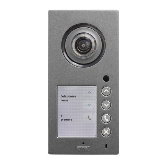
    Diese Anleitung beschreibt die Vorgehensweise zur Konfiguration und Programmierung der Tastenfelder Mikra Plus mit 4 Tasten BN 1784/3 und Mikra Digital BN 1784/4, die speziell für das 2Voice-System ausgelegt sind. 2. BESCHREIBUNG DER BESTANDTEILE FRONTAL Tastenfeld Mikra Plus Tastenfeld Mikra Digital BN 1784/3 BN 1784/4 1.
  • Seite 60: Konfiguration Des Tastenfelds Mit Wi-Fi-Verbindung

    3. KONFIGURATION DES TASTENFELDS MIT WI-FI-VERBINDUNG 3.1 VORGEHENSWEISE BEI ANSCHLUSS UND KONFIGURATION Um auf die Konfiguration der Tastenfelder BN 1784/3 und 1784/4 zugreifen zu können, muss ein Endgerät (PC, Smartphone oder Tablet) zur Verfügung stehen, das sich mit Wireless-Netzwerken verbinden kann. Die folgenden Anweisungen beachten: Den Wi-Fi-Zugangspunkt der Tastenfelder einschalten (der Wi-Fi-Zugangspunkt ist automatisch abgeschaltet).
  • Seite 61 3. Wiederholt die Taste 3 betätigen, bis auf dem Display in dem mit der Taste verbundenen Feld die dritte Ziffer des Passworts erscheint. BN 1784/3 BN 1784/4 Taste 3 Taste 3 4. Wiederholt die Taste 4 betätigen, bis auf dem Display in dem mit der Taste verbundenen Feld die vierte Ziffer des Passworts erscheint.
  • Seite 62 B.5 Somit ist es über das Endgerät möglich, zwischen den verfügbaren WLAN-Netzwerken das des Tastfeldes zu erkennen, dessen Name je nach Modell ist: - URMET_1784_3_XXXXXXXXXXXX (im Fall von Tastenfelder Mikra Plus mit 4 Tasten BN 1784/3) - URMET_1784_4_XXXXXXXXXXXX (im Fall von Mikra Digital BN 1784/4) Die Zahlen XXXXXXXXXXXX geben die MAC ADDRESS des Geräts an, die auf der Rückseite des...
  • Seite 63: Seite Tastenfeld-Einstellungen

    Sobald die Betriebssprache mit dem Symbol oben links ausgewählt wurde, ist es möglich, alle Parameter der Außenstelle zu konfigurieren und auf die folgenden Seiten zuzugreifen: – TASTEN : auf der es möglich ist, die Zuordnung der Tasten zu den Steigleitungen in der Anlage einzusehen/zu verändern (*).
  • Seite 64: Türöffnerzeit Fussgänger

    derselben Nebenaußenstelle gehört. Diese Steigleitung wird durch die Eingabe der ID der Nebenaußenstelle definiert. Dieses Merkmal wird normalerweise auf Nebenstellen eingesetzt. Wenn sie angegeben ist, gilt sie sowohl für die Elektroverriegelung der Zufahrt (Tor) als auch für die des Fußgänger-Eingangs. SELBSTEINSCHALTUNG / INTERCOM UNTERBRECHBAR Wenn eine Selbsteinschaltung oder ein Intercom-Gespräch vorliegt, erweisen sich die jeweilige Steigleitung oder das gesamte System als besetzt, können jedoch (abhängig von der Konfiguration dieses Parameters) durch einen...
  • Seite 65: Benutzerschnittstellensprache Des Displays

    KAMERABETRIEBSART (#) Der Parameter gestattet die Auswahl des Standardvideos der Kamera der Audio-Video-Außenstelle unter: • "PAL" (625 Linien/50 Hz, in den europäischen Ländern gängig); • "NTSC" (525 Linien/60 Hz, vorrangig in Nordamerika und in Japan verwendet). SELBSTEINSCHALTUNGSBEGRENZUNG ABHÄNGIG VON PARITÄT DER W.ADRESSE (#)/(&) Der Parameter aktiviert oder deaktiviert die Benutzer mit geradem Identifikationscodes, um sich im Videomodus nur auf den Außenstellen mit gerader Adresse zuschalten zu können ID=0 (wenn sekundär) oder ID=2.
  • Seite 66: Standardwerte

    AUSSENSTELLENTYP: NEBENSTELLEN Wird im Parameter AUSSENSTELLENTYP „NEBEN“ ausgewählt, erscheinen in der Webseite EINSTELLUNGEN zweii neue Parameter, die nachstehend beschrieben werden: ADRESSE ZUSTÄNDIGEN SÄULE NEBEN-AUSSENSTELLE Ist die Außenstelle eine Nebenstelle muss ihre ADRESSE ZUSTÄNDIGEN SÄULE NEBEN-AUSSENSTELLE einen Wert zwischen „0“ und „31“ aufweisen und mit der auf der Schnittstelle der Steigleitung eingegebenen Steigleitungs-ID übereinstimmen (BN 1083/50), von der sie versorgt wird.
  • Seite 67: Seite Tasten

    3.1.2 SEITE TASTEN kann auf die Website TASTEN gewechselt werden. Es öffnet sich die folgende Durch Betätigen der Taste Seite: In der Seite TASTEN werden die Liste der auf dem Gerät vorhandenen Benutzer und ihre Zuordnung zu den in der Anlage vorhandenen Steigleitungen und Wohnungen angegeben. Um einen Benutzer hinzuzufügen, müssen Vor- und Nachname des zu speichernden Benutzers im Feld “Voller Name”...
  • Seite 68: Seite Übertragen

    3.1.3 SEITE ÜBERTRAGEN wird die ÜBERTRAGEN-Webseite angezeigt. Durch Drücken des Befehls Hier können Sie: • Die soeben beschriebene Konfiguration an die Audio- oder Audio-Video-Außenstelle weiterleiten, die im Gerät mit dem Befehl gespeichert wird. Der Browser zeigt die folgenden Ansichten: Durch Betätigen des Befehls wird der Konfigurationsvorgang abgeschlossen und die folgende Meldung erscheint: •...
  • Seite 69: Reset Des Tastenfelds Auf Die Werkseitigen Parameter

    4. RESET DES TASTENFELDS AUF DIE WERKSEITIGEN PARAMETER Um die Parameter wieder auf die werkseitigen Parameter zurückzubringen, muss der Reset auf dem Tastenfeld erfolgen. Wie folgt vorgehen: A. Die Programmiertaste (10) 1 Sekunde lang betätigen. Die anschließend auszuführenden Vorgänge sind die unter den Punkten B4÷B12 beschriebenen.
  • Seite 70 3. Wiederholt die Taste 3 betätigen, bis auf dem Display in dem mit der Taste verbundenen Feld die dritte Ziffer des Passworts erscheint. BN 1784/3 BN 1784/4 Taste 3 Taste 3 4. Wiederholt die Taste 4 betätigen, bis auf dem Display in dem mit der Taste verbundenen Feld die vierte Ziffer des Passworts erscheint.
  • Seite 71: Wartung

    B.5. Durch Betätigen von erscheint folgende Ansicht: BN 1784/3 BN. 1784/4 Löscht das Löscht das Benutzerverzeichnis, Benutzerverzeichnis, stellt Daten auf stellt Daten auf werkseitige Werte und werkseitige Werte und startet Gerät neu. startet Gerät neu. Bestätigen? Bestätigen? B.6. Durch Betätigen der Taste bei dem Symbol erfolgt der Reset des Geräts und anschließend der Neustart.
  • Seite 72 NEDERLANDS Interactive Links Het document bevat INTERACTIEVE LINKS om raadpleging sneller en efficiënter te maken. INHOUDSOPGAVE 1. ALGEMENE BESCHRIJVING .......................... 73 2. BESCHRIJVING VAN DE COMPONENTEN ....................73 3. CONFIGURATIE VAN DE DEURPLAAT MET WIFI-VERBINDING ..............74 3.1 METHODE VOOR DE VERBINDING EN CONFIGURATIE ..............74 3.1.1 PAGINA INSTELLINGEN ......................
  • Seite 73: Algemene Beschrijving

    1. ALGEMENE BESCHRIjVING In deze handleiding wordt de configuratie en het programmeren beschreven van de deurplaten Mikra Plus 4 toetsen Sch. 1784/3 en Mikra Digital Sch. 1784/4 die zijn voorbehouden voor het 2Voice-systeem. 2. BESCHRIjVING VAN DE COMPONENTEN VOORKANT Deurplaat Mikra Plus Deurplaat Mikra Digital Sch.
  • Seite 74: Configuratie Van De Deurplaat Met Wifi-Verbinding

    3. CONFIGURATIE VAN DE DEURPLAAT MET WIFI-VERBINDING 3.1 METHODE VOOR DE VERBINDING EN CONFIGURATIE Om de configuratie te kunnen openen van de deurplaten Sch. 1784/3 en 1784/4 moet u beschikken over een terminal (personal computer, smartphone of tablet) die een draadloze internetverbinding kan maken. Volg onderstaande de instructies.
  • Seite 75 3. Druk herhaaldelijk de toets 3 in totdat op het display, in het vakje dat bij de toets hoort, het derde cijfer van het wachtwoord verschijnt. Sch. 1784/3 Sch. 1784/4 Toets 3 Toets 3 4. Druk herhaaldelijk de toets 4 in totdat op het display, in het vakje dat bij de toets hoort, het vierde cijfer van het wachtwoord verschijnt.
  • Seite 76 B.5 Het is daarom mogelijk om via de terminal te detecteren tussen de beschikbare WiFi-netwerken die van het knoppenpaneel, waarvan de naam, afhankelijk van het model is: - URMET_1784_3_XXXXXXXXXXXX (deurplaten Mikra Plus 4 toetsen Sch. 1784/3) - URMET_1784_4_XXXXXXXXXXXX (Mikra Digital Sch. 1784/4) De cijfers XXXXXXXXXXXX signaleren het MAC ADDRESS van het toestel dat op de achterkant van de deurplaat staat.
  • Seite 77: Pagina Instellingen

    Zodra u de werktaal heeft geselecteerd met het pictogram bovenaan links, kunt u alle parameters van de buitenpost configureren en de volgende pagina’s openen: – DE TOETSEN : daar waar de toewijzing van toetsen aan de montagekolommen in het systeem kan worden geraadpleegd/gewijzigd(*).
  • Seite 78 AUTOMATISCH INSCHAKELEN / INTERCOM ONDERBREEKBAAR Als een automatische inschakeling of een intercom-conversatie bezig is, is de bijbehorende kolom of het hele systeem bezet, maar kan dit (afhankelijk van de configuratie van deze parameter) worden onderbroken door een oproep van de buitenpost (als “JA” is geselecteerd). De parameter moet op dezelfde manier worden geprogrammeerd op alle oproepposten in het systeem.
  • Seite 79 AUTOMATISCH INSCHAKELEN BEPERKEN IN FUNCTIE VAN DE EQUIVALENTIE VAN HET WONINGADRES (#)/(&) Deze parameter schakelt de gebruikers met een even identificatiecode in of uit voor het automatisch inschakelen van de videomodus, alleen op de buitenposten met een even adres ID=0 (indien secundair) of ID=2. Hieruit volgt dat de gebruikers met een oneven identificatiecode de video-modus alleen automatisch kunnen inschakelen op buitenposten met een oneven adres ID=1 (zowel de primaire als de secundaire) of ID=3.
  • Seite 80: Standaard Waarden

    ADRES SECUNDAIR BUITENPOST In één kolom kunnen 2 secundaire buitenposten staan met een verschillend PE-adres [IDdentificatienummer (ID) van de buitenpost]. De waarde kan “0” of “1” zijn. 3.1.1.1 STANDAARD WAARDEN TYPE BUITENPOST: PRIMAIR PARAMETER STANDAARD WAARDE ADRES PRIMAIRE BUITENPOST TYPE DEUROPENER GEHEIM AUTOMATISCH INSCHAKELEN / INTERCOM ONDERBREEKBAAR GEGARANDEERDE GESPREKSTIJD...
  • Seite 81: Pagina Voor De Toetsen

    3.1.2 PAGINA VOOR DE TOETSEN opent u de webpagina TOETSEN; De volgende pagina verschijnt. Met deze toets Op de pagina TOETSEN vindt men de lijst van de gebruikers van het toestel en de kolommen die eraan zijn toegewezen en de woningen in het systeem. Om een gebruiker toe te voegen, moeten naam en achternaam van de gebruiker worden gedefinieerd die verschijnen in het veld “Volledige Naam”.
  • Seite 82: Pagina Verzenden

    3.1.3 PAGINA VERZENDEN drukt, wordt de webpagina VERZENDEN weergegeven. Als u op de opdracht Hier kunt u: • De net beschreven configuratie verzenden naar de audio-video- of audio-buitenpost en opslaan in het apparaat met het commando In de browser verschijnen de volgende pagina's: Als u op het commando drukt, is de configuratie ten einde en ziet u de volgende melding: •...
  • Seite 83: De Fabrieksparameters Van De Deurplaat Resetten

    4. DE FABRIEKSPARAMETERS VAN DE DEURPLAAT RESETTEN Om de standaard parameters weer in te stellen, moet de deurplaat gereset worden. Doe dit als volgt: A. Druk de programmeertoets (10) 1 seconde. Wat u vervolgens moet doen, is beschreven in de punten B4÷B12.
  • Seite 84 3. Druk herhaaldelijk de toets 3 in totdat op het display, in het vakje dat bij de toets hoort, het derde cijfer van het wachtwoord verschijnt. Sch. 1784/3 Sch. 1784/4 Toets 3 Toets 3 4. Druk herhaaldelijk de toets 4 in totdat op het display, in het vakje dat bij de toets hoort, het vierde cijfer van het wachtwoord verschijnt.
  • Seite 85: Onderhoud

    B.5. Als u op dit commando drukt , opent zich de volgende pagina: Sch. 1784/3 Sch. 1784/4 B.6. Als u op de toets van het pictogram drukt, wordt het toestel gereset en start het vervolgens weer 5. ONDERHOUD Wij raden aan om de voorkant van de deurplaat met een zachte, vochtige doek te reinigen. Gebruik geen alcohol bevattende producten of reinigingsproducten voor ramen.
  • Seite 86 DS1784-003...
  • Seite 87 DS1784-003...
  • Seite 88 DS1784-003 LBT20713 URMET S.p.A. Area tecnica 10154 TORINO (ITALY) servizio clienti +39 011.23.39.810 VIA BOLOGNA 188/C http://www.urmet.com Telef. +39 011.24.00.000 (RIC. AUT.) e-mail: info@urmet.com +39 011.24.00.300 - 323...

Diese Anleitung auch für:

Mikra digital1784/31784/4

Inhaltsverzeichnis