
Verwandte Anleitungen für Leica Leica DM5500 B


Inhaltszusammenfassung für Leica Leica DM5500 B
- Seite 1 Leica DM5500 B Leica DM6000 B Leica DM6000 M Operating Manual Bedienungsanleitung Manuel d’utilisation...
- Seite 2 Published September 2007 by: Herausgegeben September 2007 von: Publié en septembre 2007 par : Leica Microsystems CMS GmbH Ernst-Leitz-Straße D-35578 Wetzlar (Germany) Responsible for contents: Verantwortlich für den Inhalt: Responsable du contenu : Dr. Jasna Roeth, Stefan Motyka (Product manager „Life Science Research“) (Produktmanager „Life Science Research“)
- Seite 3 Leica DM5500 B Leica DM6000 B Leica DM6000 M Operating Manual...
- Seite 4 (in whole or in part) by print, photocopy, microfilm or other method (in- cluding electronic systems) is not allowed with- out express written permission from Leica Microsystems CMS GmbH. The term "Windows" can be used in the follow- ing text without further identification.
-
Seite 5: Inhaltsverzeichnis
Important Notes about this Manual ..7.1 Functional Principle ........39 7.2 Switching on ..........46 Intended Purpose of Microscopes ..7.3 The Leica SmartTouch ......47 7.4 The Function Keys at the stand ....48 Safety Notes ..........7.5 The Remote Control Element 3.1 General Safety Notes ....... - Seite 6 Contents Contrasting Methods for 11. Trouble Shooting ........82 Leica DM5500 B and DM6000 B ..... 72 9.1 Transmitted Light ........72 12. Care of the Microscope ......85 9.1.1 Bright Field ........72 12.1 Dust Cover ..........85 9.1.2 Phase Contrast ........ 73 12.2 Cleaning ............
-
Seite 7: Important Notes About This Manual
Therefore, it must be kept and bled, put into operation or used. taken care of. For the operation of the LeicaScreen and the Leica Application Suite (LAS), please see separate operating manual. Text symbols, pictograms and their meanings: (1.2) Numbers in parentheses, such as "(1.2)", corre-... -
Seite 8: Intended Purpose Of Microscopes
2. Intended Purpose of Microscopes 2. Intended Purpose of Microscopes The Leica DM5500 B and DM6000 B micro- scopes, to which this user manual belongs, are Caution! designed for biological routine and research applications. This includes the examination of The manufacturer assumes no liability for... -
Seite 9: Safety Notes
The responsible Leica affiliate or the main plant in Wetzlar must be consulted when- ever the device is altered, modified or used Caution! in conjunction with non-Leica components that are outside of the scope of this manual. -
Seite 10: Electrical Safety
3. Safety Notes 3.2 Electrical Safety Leica EL6000 General specifications For indoor use only. Supply voltage: 100-240 V~ (±10%) Leica CTR5500 and CTR6000 electronics box Frequency: 50-60 Hz For indoor use only. Power consumption: max. 210 VA Supply voltage: 90-250 V~ Fuses: 5x20, 2.5 A, slow,... -
Seite 11: Disposal
Caution! Through activating to the grounding connec- Before exchanging the fuses or lamps, be tion (earth screw on the back of the Leica absolutely certain to switch-off the main CTR5500 and CTR6000 Electronics Box) power switch and remove the power cable. -
Seite 12: Overview Of The Instrument
4. Overview of the Instrument 4. Overview of the Instrument Leica DM5500 B/DM6000 B Specification Leica DM6000 M • transmitted light: Contrasting Method • transmitted light: BF, Pol BF, DF, PH, ICT (DIC), Pol • incident light: • incident light: Fluo... - Seite 13 4. Overview of the Instrument Specification Leica DM5500 B/DM6000 B Leica DM6000 M Magnification Changer • manual • manual (optional) • absolute coded • absolute coded • magnification steps: • magnification steps: 1x; 1.25x; 1.6x 1x; 1.5x; 2x Objective Turret •...
- Seite 14 • Leica SmartTouch: touch sensitive LC display • SmartMove: ergonomic control element for x,y,z control with additional variable function keys • Leica STP6000: ergonomic control element for x,y,z control with 11 additional variable function keys and touch sensitive LC display •...
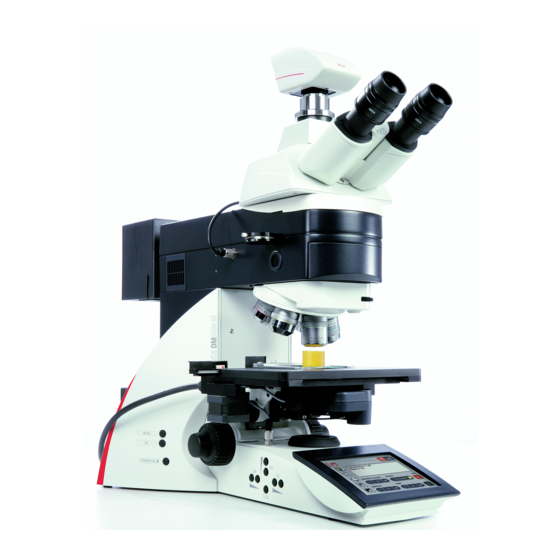
- Seite 15 4. Overview of the Instrument Abb. 1 Control elements of the Leica STP6000 Touchscreen Information key 3,4 Variable function keys, user-programmable Fine focus adjustment Coarse focus adjustment Movement in Y direction Movement in X direction Fig. 1 System overview DM6000 B...
- Seite 16 Motorized objective nosepiece with objectives 12 Focus wheel Motorized specimen stage with specimen holder Condenser 13 Variable function keys (factory pre-assigned) 14 Lamp adjustment window Leica SmartTouch n.b.: Illustrations for Leica DM5500 B similar, but with manual objective nosepiece and manual specimen stage...
- Seite 17 4. Overview of the Instrument 19 18 Fig. 3 Right side of the stand Leica DM6000 B Fig. 4 Remote control element SmartMove Movement (x-direction) 15 Lamp housing for incident light Movement (y-direction) 16 Lamp housing for transmitted light 17 Transmitted light filter, optional...
-
Seite 18: Unpacking The Microscope
5. Unpacking the Microscope 5. Unpacking the Microscope The Leica CTR5500 or CTR6000 Electronics Box, The device is delivered in several boxes. the remote control element SmartMove, the external ebq 100 supply unit* and the external The stand box contains the following compo-... - Seite 19 5. Unpacking the Microscope Installation location Transport Work with the microscope should be performed For shipping or transporting the microscope in a dust-free room, which is free of oil vapors and its accessory components, the original and other chemical vapors, as well as extreme packaging should be used.
-
Seite 20: Assembling The Microscope
6. Assembly 6. Assembling the Microscope When using intermediate systems and optical The microscope components are logically as- accessories, the sequence may vary. sembled in this order: In this case, read Chapter "6.10 Optional accessories" → p. 35. • Stage •... -
Seite 21: Stage
6. Assembly 6.1 Stage Note: Caution: For thicker specimens (Leica DM6000 M) the stage can be set to a correspondingly lower Before assembling the stage, make sure no ob- level. jectives are installed! • Place the specimen holder on the stage and Caution: fasten it with the two screws (5.1). -
Seite 22: Condenser
6. Assembly 6.2 Condenser • Screw the condenser head into the con- Note: denser. The condenser must be centered before using the microscope. • Using the condenser height adjuster (7.4), turn → Köhler illumination p. 49. the condenser holder (7.1) completely down- wards. -
Seite 23: Tube And Eyepieces
Note: For eyepieces that are not included in shipment, we recommend to learn them in with the Software Leica Application Suite (LAS), module: Fig. 13 Motorized tube connection Set-Up. This ensures that the information about Connector socket total magnification on the LeicaScreen is correct. -
Seite 24: Objectives
UV-radiation, IR-radiation). Therefore, lamps have to be operated in Note: closed housings. We recommend to perform a parfocality adjust- ment with the Software Leica Application Suite (LAS), module: Fine Tuning. Fig. 15 Releasing the fastening screw at lamp housing 107/2 Fig. - Seite 25 Caution! Do not remove the lamp’s dust cover until you have installed the lamp. Avoid finger- Fig. 18 Rear side of Leica CTR6000 Connection for lamp power cable from the stand prints on the lamp. • Replace the housing and fasten it in place us- ing the fastening screw.
-
Seite 26: Light Sources For The Incident Light Axis
6. Assembly 6.6 Light Sources for the Incident Light Axis 6.6.1 106 z lamp housing This lamp housing is used with a 12V 100W halo- gen lamp or various gas discharge lamps. Caution! Light sources pose a potential irradiation Caution! risk (glare, UV-radiation,... - Seite 27 ) (22.4). Caution! • Now connect the lamp power cable of the mi- croscope (22.5) to the Leica CTR5500 or Do not remove the lamp’s dust cover until CTR6000 electronics box (18.1, p. 25) you have installed the lamp. Avoid finger- prints on the lamp.
- Seite 28 6. Assembly Inserting the gas discharge lamps (Hg and Xe) into the 106z lamp housing Hg and Xe lamps are powered by separate sup- ply units. Read the separate instruction manual provided with these supply units. The following gas discharge lamps may be used and require different supply units and lamp mounts (Fig.
- Seite 29 6. Assembly • To open the 106 z lamp housing, unscrew the fastening screws on the cover. Caution! • Remove the transport anchorage (red plastic Hg 50 burner: rod in place of the burner) in the lamp mount. After installation, the labeling must be upright. To do so, remove the lower clamp (23.1).
- Seite 30 6. Assembly • Insert the lamp mount, with the burner in- stalled, into the lamp housing and tighten it with the screws (24.8). • Put the lid down again. Plug in the contact Fig. 24 106 z lamp housing (on the side, open) Cover raised plug as far as it goes and retighten the Collector...
- Seite 31 Connect the light guide to the microscope first to prevent exposing the user to the Fig. 27 Light guide with adapter high-energy light output of the Leica EL6000 Light guide compact light source. Adapter for Leica microscopes • Insert the light guide (27.1) into the microscope adapter (27.2) and secure it with...
-
Seite 32: Equipping The Incident Light Turret Disc
6. Assembly 6.7 Equipping the Incident Light Turret Disc Fig. 30a Removing the front cover (4-fold filter turret) The receptacles on the turret are numbered. Ac- Filter receptacle cording to your equipment, the individual filter Retention pin Front cover and/or reflector cubes have already pre-as- signed positions. -
Seite 33: Polarizer And Analyzer
• Remove the plug cap on the right side of the incident light axis (Fig. 34). Note: At the Leica DM6000 M, 2 positions for bright • Insert the polarizer into the receptacle until it field and dark field reflector cubes may be set latches in place. - Seite 34 Motorized polarizer 6.9 DIC Prisms • A motorized polarizer is already installed and With the microscopes Leica DM5500 B and ready for operation in the DIC condenser. DM6000 B the DIC objective prisms are already mounted in the DIC turret above the objective revolving nosepiece (Fig.
-
Seite 35: Optional Accessories
• Screw on the camera. Note: The use of a c-Mount or a Vario-Mount should be learned in with the Software Leica Application Suite (LAS), module: Set-up. Connecting two cameras The dual port enables you to connect two cam- eras (one digital and e.g. - Seite 36 6. Assembly Ergomodule Manual Booster Lens For raising the eye level of the tube opening, the Manual Excitation Manager ergomodule may be used. • Insert the filter slide into the front receptacle It is fastened in place with the side clamping on the right side of the stand (36.1, 37.1).
-
Seite 37: Connecting The Leica Ctr5500/Ctr6000
• Connect the motorized stage to the socket XY- Note: Stage (38a.2). We generally advise you not to use the Leica CTR5500 or CTR6000 box with other mic- • If the lamp power cable of the microscope roscopes. The serial no. of the matching stand (38b.3) has not been connected during assem-... -
Seite 38: Connecting The Computer
• When using the ebq 100 supply unit, this also has to be connected to the power supply (port 39a.1). • If using the compact light source Leica EL6000, connect it to the power supply as well (port 39b.1). Fig. 39b Rear panel of the EL6000 compact light source Port for power supply cable Fig. -
Seite 39: Startup
7. Startup 7. Startup 7.1 Functional Principle Based on an intelligent automation concept, the Leica DM5500 B or DM6000 B/M can be operated via several control elements. 1. Intelligent automation • Switch between different contrasting methods by pressing just one button. Light rings, DIC-prisms, etc. - Seite 40 7. Startup The table on the opposite page shows which mi- croscope components can be operated with Note: (Reset-Function) which control elements. The microscope can be reset to the default settings: • When the microscope is switched off, press all 3 variable function keys (40.1) on the left stand section.
- Seite 41 7. Startup Function LeicaScreen Fixed Variable Turning Knobs Software Function Function SmartMove Keys at Keys at the STP6000 the Stand Stand, at the SmartMove, STP6000 Change contrasting methods Toggle between TL and IL Select objectives (DM6000 only) learn in parfocality change operating mode (Dry/Imm) Illumination manager...
- Seite 42 7. Startup Possible assignments for the variable Function Keys at the stand and at the SmartMove For Leica DM5500 B and DM6000 B: Function key Meaning Bright field (transmitted light) Phase contrast (transmitted light) Interference contrast (transmitted light) Dark field (transmitted light)
- Seite 43 7. Startup Function key Meaning OBJ_n Select objective at position n (DM6000 B only) OBJ _1-7 Switch through objectives 1 to 7 (DM6000 B only) OBJ_7-1 Switch through objectives 7 to1 (DM6000 B only) DRY/IMM Switch between DRY / IMM objectives TOP_IN/OUT Swing condenser top in/out SHEARING+...
- Seite 44 7. Startup For Leica DM6000 M: Function key Meaning BF_RL Bright field (incident light) Interference contrast (incident light) DF_RL Dark field (incident light) POL_RL Polarization (incident light) CHANGE_RL Switch through all incident light processes INT_RL_UP Increase brightness (incident light) INT_RL_Down...
- Seite 45 7. Startup Function key Meaning CHG_FW Switch through all filter wheel functions Activate internal filter wheel EXMAN Activate Excitation Manager Activate Fluorescence Intensity Manager COMBI_CONT Combination mode (PH/fluorescence or ICT/fluorescence) CHG_COMBI Switch through all combination modes CHG_TUBE Toggle between different beam splitting modes 100%_VIS 100% Documentation port 50:50...
-
Seite 46: Switching On
Leica SmartTouch. See chapter ‘Trouble Shooting’, → p. 84. • Switch on the Leica CTR5500 or CTR6000 Electronics Box at the on/off switch (41.1). The microscopic components such as dia- When in operation, the pilot lamp will light up phragms, condenser, light and phase rings are green (41.2). -
Seite 47: The Leica Smarttouch
7. Startup 7.3 The Leica SmartTouch Navigation panel On the status page, the Leica SmartTouch The navigation panel allows for quickly select- shows the current microscope settings. The dis- ing the navigation items: play depends on the microscope’s configuration. Apart from this, the microscope can be operated via several menu levels on the LeicaScreen. -
Seite 48: The Function Keys At The Stand
The last contrast The setting of the variable function keys can method used is restored. only be altered via the Software Leica The INT (43.3) keys adjust the light intensity indi- Application Suite, module: Set-up. vidually. Settings can be made either in large or small increments. -
Seite 49: The Remote Control Element Smartmove
‘Identification Sheet’. For the list of abbreviations see page → 42f. Note: The setting of the variable function keys can only be altered via the Software Leica Application Suite (LAS), module: Set-up. 7.6 Köhler Illumination Fig. 45 Stage with specimen holder 7.6.1 Transmitted Light... - Seite 50 BF key (one of the variable the help of the two centering bolts (46.1). function keys at the stand, STP6000 or at the Leica SmartTouch). • Open the field diaphragm just enough for it to disappear from the field of view (47d).
-
Seite 51: Incident Light
IL-BF/Fluo (one of the variable func- til it just disappears from the field of view. tion keys at the stand, STP6000 or at the Leica SmartTouch). • When using a digital camera, rectangular field diaphragms are recommended. -
Seite 52: Checking Phase Contrast Rings
2/3 of the field of view. • Press the BF (Bright Field) button (one of the variable function keys at the stand, STP6000 or at the Leica SmartTouch). • In the place of an eyepiece, insert the focus- ing telescope (Fig. 49) into the observation tube. - Seite 53 7. Startup • Focus the ring structure (50a) by slightly loos- • Turn the centering screws until the dark ring ening the clamping ring (49.2) and moving the (phase ring in the objective) is congruent with eyelens (49.1). the slightly narrower bright ring (light ring in condenser) (50 c).
-
Seite 54: Adjusting Motorized Polarizer
• Activate the incident light axis using the TL/IL function key. FLUO (Leica DM5500 B/DM6000 B) or IL (Leica DM6000 M) appears in the Leica SmartTouch. • Insert the reflector cube for lamp adjustment (Fig. 52) into the filter turret in place of a filter cube. - Seite 55 7. Startup Caution! Never look directly into the beam path! When switching to the BF or Smith reflectors, there is a danger of being glared! Caution! Light sources pose a potential irradiation risk (glare, UV-radiation, IR-radiation). For the 106 z lamp housing, the direct filament im- age (for halogen lamps) or direct arc image (for gas discharge lamps), and its mirror image are fo- cused separately and adjusted to each other.
- Seite 56 7. Startup Centering the 12 V 100 W Halogen Lamp Fig. 54 Direct lamp filament image focused, but not centered • In the adjustment window, you see the direct (in reality, the image is less focused) filament image and the mirror image, which in most cases are not aligned.
- Seite 57 7. Startup Centering the Hg 50 W mercury lamp Fig. 57 Direct arc image focused but decentered (in reality, the image is less focused) • In the adjustment window, you see the direct arc image and the mirror image, which in most cases are not aligned.
- Seite 58 7. Startup Centering the Hg 100 W and Xe 75 W Fig. 60 Direct arc image focused but not centered (in reality, the image is less focused) mercury lamps • In the adjustment window, you see the direct arc image and the mirror image, which in most cases are not aligned.
- Seite 59 7. Startup Caution: In older lamps, the structure of the arc is no longer clearly recognizable. The image is then more like that of a HG 50 lamp. The im- age and mirror image can no longer be su- perimposed exactly. In this case, align both images.
-
Seite 60: Operation
If you have connected a PC, please switch on the electronics box first and the computer after- wards. Fig. 63c Front side of Leica EL6000 compact light source Fig. 63b Front view of the ebq 100 supply unit Power switch... - Seite 61 8. Operation After the initialization is completed, the status menu of the Leica SmartTouch (Fig. 64) shows Note: the current microscope setting. If initializing failed (“InitError” on the Leica SmartTouch), please see chapter “Trouble Shooting”, → p. 84. Note: (Reset-Function)
-
Seite 62: Stages And Specimen Displacement
8. Operation 8.2 Stages and Specimen Displacement Rotating the stage 8.2.1 Manual stage (DM5500 B) The swiveling range of the rotating stages is 0°- 110°. The stage can be moved with the coaxial pinion (fig. 66a.1, 66a.2). • In order to revolve the stage, loosen the fas- tening screw (66a.1). -
Seite 63: Motorized Stage (Dm6000 B/M)
8.2.2 Motorized stage (DM6000 B/M) Store and recall stage positions Specimen Displacement with SmartMove With the Software Leica Application Suite, mod- ule: Acquire, different stage positions can be The motorized stage can be moved with the temporarily stored. Only the XY position is turning knobs (66b.1, 66b.2) at the remote control... -
Seite 64: Focusing
If it is turned out of the light path, it may damage Leica DM5500 B and DM6000 B only: the condenser plug. An additional focus position, which can not be overrode, can be set. -
Seite 65: Tubes
Make sure that the connector cable is plugged settings can be changed with the Software in on the MBDT25+ motorized tube (67.1). Leica Application Suite, module: Fine Tuning. In the Coarse mode, the value is the same for all objectives. Coarse represents the maximum ve- Adjusting the Viewing Distance locity. - Seite 66 100 % extended up to 30 mm (Fig. 68). Select beam splitting via: Beam Splitting in Photo Tubes Leica SmartScree – navigation item EDT22 tube: Variable function keys at the stand The beam splitting between the observation and Leica STP6000...
-
Seite 67: Eyepieces
• the optimal setting for the aperture diaphragm object is brought into sharp focus. This does not affect the Z-position. • the settings for light intensity for the chosen contrast methode. The objective magnification and the total magni- fication appear in the Leica SmartTouch → p. 61. - Seite 68 It is possible to assign one objective to both op- eration modes, especially with dry objectives with >2mm working distance. The setting can be Caution! changed with Software Leica Application Suite, module: Fine Tuning. Follow safety data sheet for immersion oil! Changing the operation mode •...
- Seite 69 If one of the buttons for changing the operation When retrofitting objectives, they have to be mode (DRY or IMM) is pressed by mistake, the learned in with the Software Leica Application previous mode can be reactivated by pressing Suite, module: Set-up. Afterwards, parfocality the correct button.
-
Seite 70: Magnification Changer
1,25x 1,5x setting. The display on the Leica SmartTouch, 1,6x menu page ‘Light’ (fig. 74), changes accord- ingly. The selected factor is indicated in the Leica Coarse adjustment: 0-20 SmartTouch or in the corresponding window of Fine adjustment: 0-255 the Leica Application Suite software and in- cluded in the total magnification. -
Seite 71: Aperture Diaphragm And Field Diaphragm
FD keys (73.4) for the field diaphragm Leica STP6000 may be used to change each diaphragm’s set- ting at any time. The display on the Software Leica Application Suite, module: LeicaScreen, menu page ‘Light’ (Fig. 74), Acquire changes accordingly. -
Seite 72: Contrasting Methods For Leica Dm5500 B And Dm6000 B
9. Contrasting Methods for Leica DM5500 B/DM6000 B 9. Contrasting Methods for Leica DM5500 B and DM6000 B All contrasting methods can be selected and op- 9.1 Transmitted Light erated via the Leica SmartTouch, the variable 9.1.1 Bright Field (TL) function knobs, STP6000 and the Software Leica •... -
Seite 73: Phase Contrast
9. Contrasting Methods for Leica DM5500 B/DM6000 B 9.1.2 Phase Contrast 9.1.3 Dark Field (TL) • Switch to the transmitted light axis (TL) by • Switch to the transmitted light axis (TL) by pushing the TL/IL button. pushing the TL/IL button. -
Seite 74: Polarization
9. Contrasting Methods for Leica DM5500 B/DM6000 B 9.1.4 Polarization (TL) • Bring the polarizer and analyzer into cross po- sition until they reach maximum darkness. • Switch to the transmitted light axis (TL) by pushing the TL/IL button. • Insert a specimen and select an appropriate objective. -
Seite 75: Differential Interference Contrast
9. Contrasting Methods for Leica DM5500 B/DM6000 B 9.1.5 Differential Interference Contrast (TL) Alternatively: • Manually rotate the polarizer on the underside • Switch to the transmitted light axis (TL) by of the condenser into the light path (Fig. 75). -
Seite 76: Fluorescence
9. Contrasting Methods for Leica DM5500 B/DM6000 B 9.2 Fluorescence Selecting the fluorescence filter cube: • Switch to the fluorescent light axis (FLUO) by Leica SmartTouch – navigation item pushing the TL/IL button. Variable function keys at the stand and at •... -
Seite 77: Combi Mode
• Select the BGR filter cube (or another suitable duo or triple cube). • Select the combi mode. Do so by pressing the COMBI • You will see the new control field on the Leica variable key. SmartTouch under the menu item “FLUO“. Alternatively: Press the CHANGE COMBI variable key. -
Seite 78: Contrasting Methods For Leica Dm6000 M
10. Contrasting Methods for Leica DM6000 M 10. Contrasting Methods for Leica DM6000 M All contrasting methods can be selected and op- 10.1.2 Dark Field (IL) erated via the Leica SmartTouch, the variable • Switch to the incident light axis (IL) by push- function knobs and the Software Leica Applica- ing the TL/IL button. -
Seite 79: Polarization
10. Contrasting Methods for Leica DM6000 M 10.1.3 Polarization (IL) Automatic procedure: • Switch to the incident light axis (IL) by push- • The ICR filter cube is automatically brought ing the TL/IL button. into the light path. • Select the POL (polarization) contrast method. -
Seite 80: Interference Contrast
10. Contrasting Methods for Leica DM6000 M 10.1.4 Interference Contrast (IL) 10.1.5 Fluorescence • Switch to the incident light axis (IL) by push- • Switch to the incident light axis (IL) with the ing the TL/IL button. function key TL/IL. -
Seite 81: Transmitted Light
Combined procedure: 10.2.2 Polarization (TL) • For the Leica DM6000 M microscope, it is pos- • Switch to the transmitted light axis (TL) by sible to combine mechanical and motorized pushing the TL/IL button. -
Seite 82: Trouble Shooting
11. Trouble Shooting 11. Trouble Shooting Problem Cause/Remedy Stand The microscope does not respond. Make sure that voltage is impressed. Make sure that the CTR5500 or CTR6000 electronics box is connected to the power supply. Check the cable connections. Inform service technician to change the fuses. Illumination The image is completely dark. - Seite 83 11. Trouble Shooting Problem Cause/Remedy Bright Field The specimen can not be brought into focus. Use the correct immersion medium. Lay the specimen with the cover glass to- wards the top. Make sure that the cover glass thickness is correct and that it suits the indication on the objective.
- Seite 84 11. Trouble Shooting Problem Cause/Remedy Polarization No polarization contrast is possible. Bring the polarizer and analyzer into cross po- sition until they reach maximum darkness (without specimen) (→ p. 74, 79). Fluorescence The image is completely dark (no fluorescence). Open the shutter (→ p. 76). Select the incident light axis (IL) (→...
-
Seite 85: Care Of The Microscope
12. Care of the Microscope 12.Care of the Microscope 12.2 Cleaning Caution! Unplug the power supply before performing Caution: cleaning and maintenance work! Residual fiber and dust can create unwanted Protect electrical components from background fluorescence. moisture! Cleaning Coated Parts Microscopes in warm and warm-damp climatic Dust and loose dirt particles can be removed zones require special care in order to prevent... -
Seite 86: Handling Acids And Bases
Be absolutely certain to prevent the optics faces, the objectives must be sent to your and mechanical parts from coming into con- Leica subsidiary for repair. We also advise tact with these chemicals. against cleaning the inside surfaces of the eyepieces. -
Seite 87: Essential Wear And Spare Parts
13. Essential Wear and Spare Parts 13. Essential Wear and Spare Parts Order No. Material No. Name Used for Replacement Lamp 11 500 974 Halogen lamp 12 V 100 W 107/2 lamp housing 11 500 137 High-pressure mercury burner 50 W 106 z lamp housing 11 500 138 High-pressure mercury burner 100 W... -
Seite 88: Abbreviations And Pictograms
14. Abbreviations and Pictograms 14. Abbreviations and Pictograms Basic setting of microscope Contrasting method Magnification Stage and focus settings Leica SmartTouch configuration Transmitted light shutter open Transmitted light shutter closed Incident light shutter open Incident light shutter closed... - Seite 89 14. Abbreviations and Pictograms Advanced Ergo Tube Aperture diaphragm Bright field COMBI Combination contrast method CUBE Filter cube Darkfield Differential interference contrast EXMAN Excitation manager Field diaphragm Fluorescence intensity manager FLUO Fluo axis (incident light) Interference contrast (reflected light) Interference contrast (transmitted light) Ultra-fast internal filter wheel Incident light (axis) Intensity...
-
Seite 90: Index
Condenser holder 22 Incident light shutter 44 SmartMove 49, 63 Connection to power supply 38 Initialization 46, 61 Software Leica Application Suite 14, 18 Contrasting methods 12, 72, 78 Interference contrast 80 Specimen displacement 62, 63 Intermediate systems 20 Specimen holder 21... -
Seite 91: Eu Declaration Of Conformity
16. EU Declaration of Conformity 16. EU Declaration of Conformity Download: Leica DM5500 B: http://www.light-microscopy.com/down_ce-declaration_dm5500_b Leica DM6000 B: http://www.light-microscopy.com/down_ce-declaration_dm6000_b Leica DM6000 M: http://www.light-microscopy.com/down_ce-declaration_dm6000_m... - Seite 92 Leica DM5500 B Leica DM6000 B Leica DM6000 M Bedienungsanleitung...
- Seite 93 Copyrights Copyrights Alle Rechte an dieser Dokumentation liegen bei der Leica Microsystems CMS GmbH. Eine Ver- vielfältigung von Text und Abbildungen - auch von Teilen daraus - durch Druck, Fotokopie, Mi- krofilm oder andere Verfahren, inklusive elektro- nischer Systeme, ist nur mit ausdrücklicher schriftlicher Genehmigung der Leica Micro- systems CMS GmbH gestattet.
- Seite 94 Inhalt Inhalt Inbetriebnahme ......... 39 Wichtige Hinweise zur Anleitung ..7.1 Funktionsprinzip ......... 39 7.2 Einschalten ..........46 Zweckbestimmung der Mikroskope ..7.3 Der LeicaSmartTouch ....... 47 7.4 Die Funktionstasten am Stativ ....48 Sicherheitshinweise ........ 7.5 Das Fernsteuermodul SmartMove ..49 3.1 Allgemeine Sicherheitshinweise ...
- Seite 95 Inhalt Kontrastverfahren für 11. Trouble Shooting ........82 Leica DM5500 B und Leica DM6000 B .. 72 9.1 Durchlicht ........... 72 12. Pflege des Mikroskops ......85 9.1.1 Hellfeld ..........72 12.1 Staubschutz ..........85 9.1.2 Phasenkontrast ....... 73 12.2 Reinigung ............ 85 9.1.3 Dunkelfeld ........
-
Seite 96: Wichtige Hinweise Zur Anleitung
Montage, Inbetriebnahme und Gebrauch und der Zubehörteile. Sie muss daher sorgfältig sorgfältig gelesen werden. aufbewahrt werden. Für die Bedienung des LeicaScreen und der Software Leica Application Suite (LAS) liegen gesonderte Anleitungen bei. Textsymbole, Piktogramme und ihre Bedeu- tung: (1.2) Ziffern in Klammern, z.B. -
Seite 97: Zweckbestimmung Der Mikroskope
2. Zweckbestimmung der Mikroskope 2. Zweckbestimmung der Mikroskope Die Mikroskope Leica DM5500 B und DM6000 B, zu denen diese Bedienungsanleitung gehört, Achtung! sind für biologische Routine- und Forschungs- anwendungen vorgesehen. Dies schließt die Für jegliche nicht-bestimmungsgemäße Ver- Untersuchung von aus dem menschlichen wendung und bei Verwendung außerhalb... -
Seite 98: Sicherheitshinweise
Kombination mit Nicht-Lei- ca-Komponenten, die über den Umfang die- ser Anleitung hinausgehen, muss die Achtung! zuständige Leica-Vertretung oder Stammwerk in Wetzlar konsultiert werden! Um diesen Auslieferungszustand zu erhalten und einen gefahrlosen Betrieb sicherzustellen, Bei einem nicht autorisierten Eingriff in das muss der Anwender die Hinweise und Warn- Gerät oder bei nicht bestimmungsgemäßem... -
Seite 99: Elektrische Sicherheit
3. Sicherheitshinweise 3.2 Elektrische Sicherheit Leica EL6000 Allgemeine technische Daten Verwendung nur in Innenräumen. Versorgungsspannung: 100-240 V~ (±10%) Elektronikbox Leica CTR5500 und CTR6000 Frequenz: 50-60 Hz Verwendung nur in Innenräumen. Leistungsaufnahme: max. 210 VA Versorgungsspannung: 90-250 V~ Sicherungen: 5x20, 2.5 A, träge,... -
Seite 100: Entsorgung
Durch Anschluss an die Erdung (Erdungs- Schalten Sie vor dem Austausch der Siche- schraube auf der Rückseite der Elektronik- rungen oder der Lampen unbedingt den box Leica CTR5500 und CTR6000) können an Netzschalter aus und entfernen Sie das das Mikroskop angeschlossene Zusatzgerä- Netzkabel. -
Seite 101: Geräteübersicht
4. Geräteübersicht 4. Geräteübersicht Leica DM5500 B/DM6000 B Spezifikation Leica DM6000 M • Durchlicht: BF, DF, PH, Kontrastverfahren • Durchlicht: BF, Pol ICT (DIC), Pol • Auflicht: BF, DF, ICR (DIC), • Auflicht: Fluo Pol, Fluo Durchlichtachse • automatischer Beleuchtungsmanager (autom. - Seite 102 4. Geräteübersicht Spezifikation Leica DM5500 B/DM6000 B Leica DM6000 M Vergrößerungswechsler • manuell • manuell (optional) • 3-fach absolut codiert • 3-fach absolut codiert • Vergrößerungsstufen: • Vergrößerungsstufen: 1x; 1,25x; 1,6x 1x; 1,5x; 2x Objektivrevolver • DM6000 B: motorisiert • motorisiert DM5500 B: manuell •...
- Seite 103 • Handräder zum Fokussieren • Leica SmartTouch: Berührungsempfindliches LC-Display • SmartMove: Ergonomisches Bedienelement für x,y,z-Kontrolle mit zusätzlichen variablen Funktionstasten • Leica STP6000: Ergonomisches Bedienelement für x,y,z-Kontrolle mit 11 zusätzlichen variablen Funktions- tasten und Berührungsempfindliches LC-Display • separate Einheit für die Steuerung von Elektronikbox •...
- Seite 104 4. Geräteübersicht Abb. 1 Bedienelemente des Leica STP6000 Touchscreen Informationstaste 3,4 Variable Funktionstasten, frei programmierbar Fokus-Feineinstellung Fokus-Grobeinstellung Verfahren in Y-Richtung Verfahren in X-Richtung Abb. 2 Gesamtansicht Leica DM6000 B...
- Seite 105 Motorisierter Tubus MBDT 11 Bedientasten für Helligkeitseinstellung Motorisierter Objektivrevolver mit Objektiven Motorisierter Präparatetisch mit Präparatehalter 12 Fokushandrad 13 Variable Funktionstasten (werkseitig vorbelegt) Kondensor 14 Lampen-Justierfenster Leica SmartTouch Hinweis: Abbildungen für Leica DM5500 B analog, jedoch mit manuellem Objektivrevolver und manuellem Präparatetisch...
- Seite 106 4. Geräteübersicht 19 18 Abb. 3 Rechte Stativseite Leica DM6000 B Abb. 4 Fernsteuermodul SmartMove Verfahren in X-Richtung 15 Lampenhaus für Auflicht 16 Lampenhaus für Durchlicht Verfahren in Y-Richtung Fokuseinstellung 17 Durchlichtfilter, optional 18 Durchlichtfilter, optional Variable Funktionstasten (werkseitig vorbelegt)
-
Seite 107: Auspacken
• Präparatetisch mit Tischwinkel • Netzkabel und PC-Verbindungskabel Hinweis: Das Berühren der Linsenoberfläche der Objekti- • CD mit dem Softwarepaket Leica Application Suite (LAS) ve ist möglichst zu vermeiden. Entstehen den- noch Fingerabdrücke auf den Glasflächen, so • Anleitungen und Liste der Mikroskopvorein- sind diese mit einem weichen Leder- oder stellung („Identification Sheet“) - Seite 108 5. Auspacken Aufstellungsort Transport Das Arbeiten mit dem Mikroskop sollte in einem Für den Versand oder Transport des Mikroskops staubfreien Raum erfolgen, der frei von Öl- und und seiner Zubehörkomponenten sollte die anderen chemischen Dämpfen und extremer Originalverpackung verwendet werden. Luftfeuchtigkeit ist.
-
Seite 109: Montage Des Mikroskops
6. Montage 6. Montage des Mikroskops Bei Verwendung von Zwischensystemen und Die Mikroskopkomponenten werden sinnvoller- optischem Zubehör kann die Reihenfolge ab- weise in dieser Reihenfolge montiert: weichen. Lesen Sie dazu das Kapitel • Objekttisch „6.10 Optionales Zubehör“ → S. 35. •... -
Seite 110: Objekttisch
6. Montage 6.1 Objekttisch Hinweis: Achtung: Bei dickeren Präparaten (Leica DM6000 M) kann der Tisch entsprechend niedriger angesetzt Vor dem Montieren des Objekttisches dürfen werden. noch keine Objektive eingeschraubt sein! Achtung: • Setzen Sie den Präparatehalter auf den Tisch auf und befestigen Sie ihn mit den beiden Dadurch werden die zuvor definierte Fokus- Schrauben (5.1). -
Seite 111: Kondensor
6. Montage 6.2 Kondensor • Schrauben Sie den Kondensorkopf in den Hinweis: Kondensor ein. Vor dem Mikroskopieren muss der Kondensor zentriert werden. • Drehen Sie den Kondensorhalter (7.1) mittels → Köhlersche Beleuchtung S. 49. der Kondensorhöhenverstellung (7.4) ganz nach unten. Abb. -
Seite 112: Tubus Und Okulare
• Die Okulare werden in die Okularstutzen am Tubus eingesetzt. Hinweis: Es wird empfohlen, Okulare, die nicht im Liefer- umfang enthalten sind, über die Software Leica Abb. 13 Anschluss motorischer Tubus Application Suite (LAS) - Modul: Set-Up einzu- Anschlussbuchse lernen. -
Seite 113: Objektive
Gefährdung durch Strahlung (Blendung, UV- Strahlung, IR-Strahlung). Lampen müssen daher in geschlossenen Gehäusen betrie- Hinweis: ben werden. Es wird empfohlen, einen Parfokalitätsausgleich über die Software Leica Application Suite (LAS) Abb. 15 - Modul: Fine Tuning durchzuführen. Lösen der Befesti- gungsschraube am Lampenhaus 107/2 Abb. - Seite 114 Sie es mit der seitlichen Klemm- schraube. • Schließen Sie das Lampenhaus an die Strom- versorgung für Durchlicht (Symbol: ) (17.3) • Verbinden Sie dann das Kabel für die Lampen- versorgung (17.5) mit der Elektronikbox Leica CTR5500 oder CTR6000 (18.1).
-
Seite 115: Lichtquellen Für Die Auflichtachse
6. Montage 6.6 Lichtquellen für die Auflichtachse 6.6.1 Lampenhaus 106 z Dieses Lampenhaus wird mit einer Halogen- glühlampe 12V 100W oder verschiedenen Gas- Achtung! entladungslampen verwendet. Es besteht generell bei den Lichtquellen die Achtung! Gefährdung durch Strahlung (Blendung, UV- Strahlung, IR-Strahlung). Lampen müssen daher in geschlossenen Gehäusen betrie- Beachten Sie unbedingt die Gebrauchsan- ben werden. - Seite 116 Auflicht (Symbol ) (22.4) an. ein. • Verbinden Sie dann das Kabel für die Lampen- versorgung (22.5) mit der Elektronikbox Leica Achtung! CTR5500 oder CTR6000 (18.1, S.25). Schutzhülle der Lampe erst nach dem Ein- setzen entfernen. Fingerabdrücke unbedingt vermeiden.
- Seite 117 6. Montage Einsetzen der Gasentladungslampen (Hg und Xe) in das Lampenhaus 106z Hg- und Xe-Lampen werden mit separaten Vor- schaltgeräten betrieben. Bitte unbedingt die gesonderte Anleitung dieser Vorschaltgeräte beachten. Folgende Gasentladungslampen sind einsetzbar erfordern unterschiedliche Stromver- sorgungsgeräte und Lampenfassungen (Abb. 23): Typische Lebensdauer* Hg-Höchstdrucklampe 50 W (Wechselstrom) 100 h...
- Seite 118 6. Montage • Zum Öffnen des Lampenhauses 106 z lösen Sie die Befestigungsschrauben am Ver- Achtung! schlussdeckel. Hg 50-Brenner: • Entfernen Sie die Transportsicherung (roter Die Beschriftung muss nach dem Einbau Kunststoffstab anstelle des Brenners) der aufrecht stehen. Ein evtl. vorhandener Glas- Lampenfassung.
- Seite 119 6. Montage • Setzen Sie die Lampenfassung wieder ein und ziehen Sie die Befestigungsschrauben (24.8) wieder an. Abb. 24 Lampenhaus 106 z (seitlich, geöffnet) • Schließen Sie das Lampenhaus und ziehen Deckel hochgestellt Sie die Befestigungsschrauben wieder an. Kollektor Glühlampe 12 V 100 W oder •...
- Seite 120 6. Montage 6.6.2 Externe Kompaktlichtquelle Leica EL6000 Achtung! • Das Einsetzen der Lampe entnehmen Sie bitte der Anleitung zur Kompaktlichtquelle Leica Schließen Sie den Lichtleiter beidseitig an EL6000. (Lichtquelle/Adapter) bevor Sie den Shutter oder den Attenuator öffnen! • An der Rückseite des Stativs wird der Das austretende Licht kann zu Schäden an...
-
Seite 121: Bestückung Der Auflicht-Revolverscheibe
6. Montage 6.7 Bestückung der Auflicht-Revolverscheibe Abb. 30a Entfernen der Frontabdeckung (4-fach Filterrevolverscheibe) Die Aufnahmen an der Revolverscheibe sind Filteraufnahme nummeriert. Entsprechend Ihrer Ausrüstung Arretierungsstift Frontabdeckung sind den einzelnen Filter-bzw. Reflektorwürfeln bereits werkseitig bestimmte Positionen zuge- ordnet. Eine Aufstellung liegt Ihrer Lieferung bei („Identification Sheet“). -
Seite 122: Polarisator Und Analysator
Seite der Auflichtachse (Abb. 34). • Schieben Sie den Polarisator bis zur Rastung Hinweis: in die Aufnahme. Beim Leica DM6000 M können, je nach Ausrü- stung, bis zu zwei Positionen für Hellfeld- und Achtung: Dunkelfeld- Reflektorwürfel vorgegeben sein. Polarisator nur in die vordere Aufnahme schieben. -
Seite 123: Dic-Prismen
6. Montage Motorischer Polarisator 6.9 DIC-Prismen • Im Kondensor DIC ist ein motorischer Polari- Bei den Mikroskopen Leica DM5500 B und sator bereits eingebaut und betriebsbereit. DM6000 B sind die DIC-Prismen bereits in der DIC-Scheibe oberhalb des Objektivrevolvers eingesetzt (Abb. 34.2). -
Seite 124: Optionales Zubehör
Service zentriert werden. • Schrauben Sie die Kamera auf. Hinweis: Die Verwendung eines c-Mounts bzw. eines Vario-Mounts sollte über die Software Leica Application Suite (LAS) - Modul: Set-Up einge- lernt werden. Anschluss von zwei Kameras Über einen Duo-Aufsatz können auch zwei Ka- meras, eine Digitalkamera und z. - Seite 125 6. Montage Ergomodul Manuelle Booster-Linse Manueller Excitation-Manager Zur Erhöhung des Tubuseinblicks kann zwischen Tubus und Tubusaufnahme das Ergomodul ein- • Setzen Sie den Filterschieber in die vordere gesetzt werden. Aufnahme an der rechten Stativseite ein Die Befestigung erfolgt durch die seitliche (36.1, 37.1).
-
Seite 126: Anschluss An Die Elektronikbox Ctr5500/Ctr6000
Buchse XYZ-Control für SmartMove Buchse Trigger Buchse Ext Abb. 38b Stativrückseite USB Schnittstelle USB-Schnittstelle Anschluss Elektronikbox Leica CTR5500 bzw. CTR6000 Buchse 12V, max 100W für das Lampenkabel des Stativs DL: Reset-Knopf Lampenversorgungskabel des Stativs Buchse Microscope für Mikroskop Ext1/Ext2 Buchsen... -
Seite 127: Anschluss An Den Computer
• Falls das externe Vorschaltgerät ebq 100 ver- wendet wird, schließen Sie auch dieses an die Spannungsversorgung an (Buchse 39a.1). • Bei Verwendung der Kompaktlichtquelle Leica EL6000 verbinden Sie diese ebenfalls mit der Spannungsversorgung (Buchse 39b.1). Abb. 39b Rückseite der Kompaktlichtquelle EL6000 Buchse für Netzkabel Abb. -
Seite 128: Inbetriebnahme
7. Inbetriebnahme 7. Inbetriebnahme 7.1 Funktionsprinzip Aufbauend auf einer intelligenten Automatisierung kann das Leica DM5500 B bzw. DM6000 B/M über verschiedene Bedienelemente gesteuert werden. 1. Intelligente Automatisierung • Umschalten zwischen verschiedenen Kontrastverfahren auf Knopfdruck. Lichtringe, DIC- Prismen, etc. werden automatisch in den Strahlengang gebracht. - Seite 129 7. Inbetriebnahme Die Tabelle auf der folgenden Seite gibt einen Überblick, welche Mikroskopkomponenten über Hinweis: (Reset-Funktion) die jeweiligen Bedienelemente gesteuert wer- den können. Das Mikroskop kann auf die werkseitig pro- grammierten Funktionen zurückgesetzt werden: • Drücken Sie im ausgeschalteten Zustand alle 3 variablen Funktionstasten (40.1) auf dem lin- ken Stativflügel.
- Seite 130 7. Inbetriebnahme Funktion LeicaScreen Festgelegte Variable Drehknöpfe Software Funktions- Funktions- SmartMove tasten tasten STP6000 Stativ Stativ, SmartMove, STP6000 Kontrastverfahren wechseln Durchlicht/Auflichtachse wechseln Objektive anfahren (nur DM6000) Parfokalität einlernen Betriebsmodus ändern (Dry/Imm) Beleuchtungsmanager Vergrößerungswechsler* nur manuell Fokussierung Setzen der Schwellen Anfahren der Schwellen Schrittweite ändern (Coarse/Fine) XY-Tischpositionierung...
- Seite 131 7. Inbetriebnahme Möglichen Belegungen der variablen Funktionstasten am Stativ und SmartMove Für Leica DM5500 B und DM6000 B: Funktionstaste Bedeutung Hellfeld Durchlicht Phasenkontrast Durchlicht Interferenzkontrast Durchlicht Dunkelfeld Durchlicht Polarisation Durchlicht CHANGE_TL Alle Durchlichtkontrastverfahren durchschalten INT_TL_UP Helligkeit erhöhen (Durchlicht) INT_TL_DOWN Helligkeit reduzieren (Durchlicht) FD_TL_UP Feldblende öffnen (Durchlicht)
- Seite 132 7. Inbetriebnahme Funktionstaste Bedeutung OBJ_n Objektiv an Position n wählen (nur DM6000 B) OBJ _1-7 Objektive 1 bis 7 durchschalten (nur DM6000 B) OBJ_7-1 Objektive7 bis 1 durchschalten (nur DM6000 B) DRY/IMM Wechsel des Betriebsmodus Trocken/Immersion TOP_IN/OUT Kondensorkopf ein-/ausschwenken SHEARING+ Wechsel der Objektivprismen für DIC Z_FINE Feinfokus aktivieren...
- Seite 133 7. Inbetriebnahme Für Leica DM6000 M: Funktionstaste Bedeutung BF_RL Hellfeld Auflicht Interferenzkontrast Auflicht DF_RL Dunkelfeld Auflicht POL_RL Polarisation Auflicht CHANGE_RL Alle Auflichtkontrastverfahren durchschalten INT_RL_UP Helligkeit erhöhen (Auflicht) INT_RL_DOWN Helligkeit reduzieren (Auflicht) FD_RL_UP Feldblende öffnen (Auflicht) FD_RL_DOWN Feldblende schließen (Auflicht) AP_RL_UP Aperturblende öffnen (Auflicht)
- Seite 134 7. Inbetriebnahme Funktionstaste Bedeutung CHG_FW Filterradfunktionen durchschalten Internes Filterrad aktivieren EXMAN Excitation-Manager aktivieren Fluoreszenz-Intensitätsmanager aktivieren COMBI_CONT Kombinationsverfahren (BF RL und BF TL) CHG_COMBI Alle Kombinationsverfahren durchschalten CHG_TUBE Unterschiedliche Strahlenteilung durchschalten 100%_VIS 100% Beobachtungsausgang 50:50 50% Beobachtungsausgang/50% Kamera 100%_CAM 100% Kamera OBJ_n Objektiv an Position n wählen OBJ+...
-
Seite 135: Einschalten
Haben Sie einen PC angeschlossen, so schalten Sie zuerst die Elektronikbox und danach den Computer ein. Achtung! Nach Abschluss der Initialisierung wird im Leica Nach dem Einschalten der Gasentladungs- SmartTouch die aktuelle Mikroskopeinstellung lampe muss der Brenner sofort justiert wer- angezeigt (Abb. -
Seite 136: Der Leicasmarttouch
7. Inbetriebnahme 7.3 Der Leica SmartTouch Navigationsleiste Der Leica SmartTouch zeigt auf der Statusseite Die Navigationsleiste ermöglicht den schnellen die aktuellen Mikroskopeinstellungen. Die An- Wechsel zwischen den Navigationspunkten: zeige hängt von der jeweiligen Mikroskopaus- rüstung ab. Darüberhinaus kann über das Aufru- fen verschiedener Menüseiten das Mikroskop... -
Seite 137: Die Funktionstasten Am Stativ
Hinweis: licht- und Durchlichtachse um. Dabei wird Das Ändern der Tastenbelegung ist nur über jeweils das zuletzt genutzte Kontrastverfahren die Software Leica Application Suite - Modul: wiedereingestellt. Set-Up möglich. Mit den Tasten INT (43.3) wird die Lichtintensität individuell angepasst. Die Einstellung kann in groben und feinen Schritten erfolgen. -
Seite 138: Das Fernsteuermodul Smartmove
„Identification Sheet“. Die Bedeutung der Abkürzungen entnehmen Sie bitte der Liste → S. 42f. Hinweis: Das Ändern der Tastenbelegung ist nur über die Software Leica Application Suite (LAS) - Modul: Set-Up möglich. 7.6 Köhlersche Beleuchtung Abb. 45 Tisch mit Präparatehalter Präparatehalter 7.6.1 Durchlicht... - Seite 139 Drücken der Taste BF (eine der varia- feldes bewegt werden. blen Funktionstasten am Stativ, STP6000 oder auf dem Leica SmartTouch). • Öffnen Sie die Leuchtfeldblende so weit, dass sie gerade aus dem Sehfeld verschwindet • Legen Sie nun ein Präparat in den Präparate- (47d).
-
Seite 140: Auflicht
7. Inbetriebnahme 7.6.2 Auflicht • Fokussieren Sie auf das Präparat mit dem SmartMove, STP6000 oder Fokus- Für jedes Objektiv sind bereits sinnvolle Werte handrädern. für die Aperturblende und die Leuchtfeldblende eingestellt. Außerdem ist das Auflichtmodul be- • Stellen Sie die Lichtintensität mit den Tasten reits werkseitig zentriert. -
Seite 141: Phasenkontrastringe Überprüfen
7. Inbetriebnahme Justieren der Aperturblende (nur für DM6000 M) 7.7 Phasenkontrastringe überprüfen • Entfernen Sie ein Okular (z.B. rechts). Ist Ihr Mikroskop für die Verwendung von Phasenkontrast ausgerüstet, sind im Kondensor • Schließen Sie die Aperturblende mit der Funk- die zu den Objektiven passenden Lichtringe ein- tionstaste AP (43.2) bis der Rand der Blende in gebaut. - Seite 142 7. Inbetriebnahme • Stellen Sie die Ringstruktur (50a) scharf, in- • Drehen Sie die Zentrierschlüssel, bis der dem Sie den Klemmring (49.2) etwas lockern dunkle Ring (Phasenring im Objektiv) de- und die Augenlinse (49.1) verschieben. ckungsgleich mit dem geringfügig schmaleren hellen Ring (Lichtring im Kondensor) ist (50c).
-
Seite 143: Einstellung Des Motorischen Polarisators
• Aktivieren Sie bei Bedarf die Auflichtachse mit der Funktionstaste TL/IL. Es erscheint FLUO (Leica DM5500 B/DM6000 B) oder IL (Leica DM6000 M) im Leica SmartTouch. • Setzen Sie den Reflektor zur Lampen- justierung (Abb. 52) statt eines Filterwürfels in den Filterrevolver ein. - Seite 144 7. Inbetriebnahme Achtung! Nie in den direkten Strahlengang blicken! Bei Umschaltung auf Reflektor BF oder Smith besteht Blendgefahr! Achtung! Es besteht generell bei den Lichtquellen die Gefährdung durch Strahlung (Blendung, UV- Strahlung, IR-Strahlung). Beim Lampenhaus 106 z werden direktes Wendelbild (bei Halogen-Glühlampe) bzw. direk- tes Bild des Lichtbogens (bei Gasentladungs- lampen) und dessen Spiegelbild getrennt fokus- siert und zueinander justiert.
- Seite 145 7. Inbetriebnahme Zentrieren der Halogen-Glühlampe 12 V 100 W Abb. 54 Direktes Wendelbild fokussiert, aber dezentriert (in Wirklichkeit ist das Bild unschärfer) • Im Justierfenster sehen Sie das direkte Wendelbild und das Spiegelbild, die in der Re- gel gegeneinander verschoben sind. •...
- Seite 146 7. Inbetriebnahme Zentrieren der Quecksilberlampe Hg 50 W Abb. 57 Direktes Bild des Lichtbogens fokussiert, aber dezentriert (in Wirklichkeit ist das Bild • Im Justierfenster sehen Sie das direkte Bild unschärfer) des Lichtbogens und das Spiegelbild, die in der Regel gegeneinander verschoben sind. •...
- Seite 147 7. Inbetriebnahme Zentrieren der Quecksilberlampen Abb. 60 Direktes Bild des Lichtbogens fokussiert, aber dezentriert (in Wirklichkeit ist das Bild Hg 100 W und Xe 75 W unschärfer) • Im Justierfenster sehen Sie das direkte Bild des Lichtbogens und das Spiegelbild, die in der Regel gegeneinander verschoben sind.
- Seite 148 7. Inbetriebnahme Achtung! Bei älteren Lampen ist die Struktur des Lichtbogens nicht mehr klar erkennbar. Das Bild ähnelt dann mehr dem einer HG 50-Lam- pe. Bild und Spiegelbild können daher nicht mehr exakt übereinander plaziert werden. Bringen Sie in diesem Fall beide Bilder zur Deckung.
-
Seite 149: Bedienung
Initialisierungs- Bei Verwendung einer Gasentladungslampe phase. muss das Vorschaltgerät ebq 100 zunächst se- parat eingeschaltet werden (63b.1). Abb. 63a Ebenso muss die externe Lichtquelle Leica Vorderseite EL6000 gegebenenfalls am Netzschalter (63c.1) Leica CTR6000 eingeschaltet werden. Ein/Aus-Schalter Kontrolllampe Schalten Sie die Elektronikbox CTR5500 bzw. - Seite 150 8. Bedienung Nach Abschluss der Initialisierung wird im Leica SmartTouch die Statusseite mit der aktu- Hinweis: ellen Mikroskopeinstellung angezeigt (Abb. 64). Bei fehlerhafter Initialisierung ( „Init Error“-Mel- dung auf dem Leica SmartTouch) siehe Kapitel Trouble Shooting → S. 84. Hinweis: (Reset-Funktion) Bei der Initialisierung fährt der Tisch an eine...
-
Seite 151: Tische Und Objektverschiebung
8. Bedienung 8.2 Tische und Objektverschiebung Drehen des Tisches 8.2.1 Manueller Tisch (DM5500 B) Der Schwenkbereich bei den drehbaren Tischen beträgt 0°- 110°. Das Verfahren des Tisches erfolgt über den Koaxialtrieb (Abb. 66a.1, 66a.2). • Um den Tisch zu drehen, lösen Sie die Fest- stellschraube (66a.1). -
Seite 152: Motorischer Tisch (Dm6000 B/M)
8.2.2 Motorischer Tisch (DM6000 B/M) Tischpositionen speichern und anfahren Objektverschiebung über SmartMove Es können verschiedene Tischpositionen über die Software Leica Application Suite - Modul: Das Verfahren des motorischen Tisches erfolgt Acquire temporär gespeichert werden. Dabei über die Drehknöpfe (66b.1, 66b.2) am Fernsteuer- wird die XY-Position, nicht jedoch die aktuelle Z- modul SmartMove oder STP6000 (66c.7, 66c.8). -
Seite 153: Fokussierung
überfahren werden. polarisator* eingeschwenkt ist, wenn der Tisch auf die unterste Position gefahren Nur für Leica DM5500 B und DM6000 B: wird. Ein ausgeschwenkter Polarisator kann Zusätzlich kann eine Fokusposition, die nicht den Kondensorstecker beschädigen. -
Seite 154: Tuben
Die Werte sind bereits sinnvoll vor- bus MBDT25+ das Anschlusskabel eingesteckt definiert. Die Zuordnung kann über die Software ist (67.1). Leica Application Suite - Modul: Fine Tuning ge- ändert werden. Augenabstand einstellen Wird der Wert Coarse gewählt, ist die Ver- •... - Seite 155 Tubus EDT22: Variable Funktionstasten am Stativ Die Lichtaufteilung zwischen Beobachtungs- Leica STP6000 und Dokumentationsausgang ist fest eingestellt (50:50). Software Leica Application Suite-Modul: Acquire Tubus BDT25+: Die Lichtaufteilung wird manuell durch Heraus- Tubus HC L 2TU: ziehen einer Schaltstange eingestellt. Die Lichtaufteilung wird manuell durch Heraus- ziehen einer Schaltstange eingestellt.
-
Seite 156: Okulare
Es wird empfohlen, Okulare, die nicht im Liefer- Hinweis: umfang enthalten sind oder nachgerüstet Der Blendschutz der Okulare muss beim Mikro- werden, über die Software Leica Application skopieren mit Brille abgenommen bzw. zurück- Suite-Modul: Set-Up einzulernen. Dadurch ist gestülpt werden. - Seite 157 Ölimmersion. Es ist möglich ein Objektiv beiden Betriebsmodi zuzuordnen, insbesondere bei Trockenobjek- Achtung! tiven mit einem Arbeitsabstand > 2mm. Die Zuordnung erfolgt über die Software Leica Sicherheitsdatenblatt zum Immersionsöl be- Application Suite-Modul: Fine Tuning. achten! Wechsel des Betriebsmodus Anfahren der Objektive •...
- Seite 158 Wurde versehentlich eine der Tasten Imm oder Werden Objektive nachgerüstet, müssen sie Dry für den Wechsel des Betriebsmodus ge- über die Software Leica Application Suite - Mo- drückt, kann der ursprüngliche Modus durch dul: Set-Up eingelernt werden. Danach sollte Drücken der entsprechenden Taste wieder her- ebenfalls die Parfokalität neu eingelernt wer-...
-
Seite 159: Vergrößerungswechsler
1,5x beiden INT-Tasten schaltet zwischen Grob-und 1,6x Feineinstellung um. Die Anzeige der Licht- intensität im Leica SmartTouch, Menüseite Der gewählte Faktor wird im Leica SmartTouch, bzw. Light (Abb. 74), ändert sich entsprechend. im entsprechenden Fenster der Software Leica Grobeinstellung: 0-20... -
Seite 160: Aperturblende Und Leuchtfeldblende
Bei Verwendung von PH oder DF ist die Apertur- blende voll geöffnet und kann nicht geschlossen werden. Blenden einstellen über Feste Funktionstasten am Stativ Leica SmartTouch Abb. 74 Menüseite Light des LeicaScreens Variable Funktionstasten am Stativ und SmartMove Leica STP6000 Software Leica Application Suite – Modul: Acquire... -
Seite 161: Kontrastverfahren Für Leica Dm5500 B Und Leica Dm6000 B
9. Kontrastverfahren für Leica DM5500 B/DM6000 B 9. Kontrastverfahren für Leica DM5500 B und Leica DM6000 B Alle Kontrastverfahren können sowohl über die 9.1 Durchlicht Tasten des Leica SmartTouch wie auch über va- 9.1.1 Hellfeld (TL) riable Funktionstasten, STP6000 und die Softwa- •... -
Seite 162: Phasenkontrast
9. Kontrastverfahren für Leica DM5500 B/DM6000 B 9.1.2 Phasenkontrast 9.1.3 Dunkelfeld (TL) • Schalten Sie mit der Funktionstaste TL/IL auf • Schalten Sie mit der Funktionstaste TL/IL auf die Durchlichtachse (TL) um. die Durchlichtachse (TL) um. • Wählen Kontrastverfahren • Wählen Kontrastverfahren (Phasenkontrast). -
Seite 163: Polarisation
Auch der Analysator-Würfel wird automa- tisch in den Strahlengang gebracht. Manuelles Verfahren: Kombinierte Verfahren: • Beim Mikroskop Leica DM5500 B/DM6000 B be- • Schwenken Sie den Polarisator an der Unter- seite des Kondensors in den Strahlengang ein steht die Möglichkeit, rein mechanische und (Abb. -
Seite 164: Differentieller Interferenzkontrast (Tl)
9. Kontrastverfahren für Leica DM5500 B/DM6000 B 9.1.5 Differentieller Interferenzkontrast (TL) Alternativ: • Schwenken Sie den Polarisator an der • Schalten Sie mit der Funktionstaste TL/IL auf Kondensorunterseite manuell in den Strahlen- die Durchlichtachse (TL) um. gang ein (Abb. 75). - Seite 165 9. Kontrastverfahren für Leica DM5500 B/DM6000 B 9.2 Fluoreszenz Wechsel des Fluoreszenz-Filterwürfels • Schalten Sie mit der Funktionstaste TL/IL auf Leica SmartTouch-Navigationspunkt die Fluoachse (FLUO) um. Variable Funktionstasten am Stativ und SmartMove: Cube CW or Cube CCW • Legen Sie ein Präparat auf und fahren Sie ein Leica STP6000 geeignetes Objektiv an.
-
Seite 166: Kombi-Verfahren
9. Kontrastverfahren für Leica DM5500 B/DM6000 B • Ist das Mikroskop mit einem ultraschnellen in- 9.3 Kombi-Verfahren ternen Filterrad* und einem motorischen Je nach Ausstattung Ihres Mikroskops sind bis Excitation-Manager* ausgerüstet, verfahren zu zwei Kombi-Verfahren möglich: Sie folgendermaßen: FLUO/PH und FLUO/DIC •... -
Seite 167: Kontrastverfahren Für Leica Dm6000 M
10.Kontrastverfahren für Leica DM6000 M Alle Kontrastverfahren können sowohl über die 10.1.2 Dunkelfeld (IL) Tasten des Leica SmartTouch wie auch über va- • Schalten Sie mit der Funktionstaste TL/IL auf riable Funktionstasten und die Software „Leica die Auflichtachse (IL) um. -
Seite 168: Polarisation
CHANGE RL Sie dann Polarisator und Analysator bis zur (Tastenbelegung siehe „Identification Sheet“) maximalen Dunkelheit in Kreuzstellung. Auf der Statusseite des Leica SmartTouch er- scheint POL. • Legen Sie ein geeignetes Präparat auf und fahren Sie ein entsprechendes Objektiv an. -
Seite 169: Interferenzkontrast
• Legen Sie ein Präparat auf und fahren Sie ein geeignetes Objektiv an. geeignetes Objektiv an. • Wählen Sie das Kontrastverfahren DIC. • Auf der Statusseite des Leica SmartTouch er- Drücken Sie dazu die variable Taste DIC. scheint der aktuelle Fluoreszenz-Filterwürfel Alternativ: Drücken Sie die variable Taste... -
Seite 170: Durchlicht
• Schalten Sie mit der Funktionstaste TL/IL auf die Durchlichtachse (TL) um. Kombinierte Verfahren: • Wählen Sie das Kontrastverfahren POL (Pola- • Beim Mikroskop Leica DM6000 M besteht die risation). Möglichkeit, rein mechanische und motori- Drücken Sie dazu die variable Taste POL. -
Seite 171: Trouble Shooting
11. Trouble Shooting Problem Ursache/Abhilfe Stativ Das Mikroskop reagiert nicht. Stellen Sie sicher, dass Spannung auf der Steckdose liegt. Stellen Sie sicher, dass die Elektronikbox CTR5500 bzw. CTR6000 an das Netz ange- schlossen ist. Überprüfen Sie die Kabelverbindungen. Informieren Sie den Service und lassen Sie überprüfen, ob die Sicherung defekt ist. - Seite 172 11. Trouble Shooting Problem Ursache/Abhilfe Hellfeld Das Präparat ist nicht zu fokussieren. Verwenden Sie das korrekte Immersions- medium. Legen Sie das Präparat mit dem Deckglas nach oben. Stellen Sie sicher, dass die Deckglasdicke korrekt ist und mit den Angaben am Objektiv übereinstimmt.
- Seite 173 11. Trouble Shooting Problem Ursache/Abhilfe Polarisation Es lässt sich kein Polarisationskontrast ein- Kreuzen Sie Polarisator und Analysator bis zur stellen. maximalen Dunkelheit (ohne Präparat) (→ S. 74, 79). Fluoreszenz Das Bild ist absolut dunkel (keine Fluoreszenz). Öffnen Sie den Shutter (→ S. 76). Wählen Sie die Auflichtachse (IL) an (→...
-
Seite 174: Pflege Des Mikroskops
12. Pflege des Mikroskops 12.Pflege des Mikroskops 12.2 Reinigung Achtung! Vor Reinigungs- und Wartungsarbeiten Netz- Achtung: stecker ziehen! Faser- Staubreste können Elektrische Komponenten vor Feuchtigkeit Fluoreszenzmikroskopie störende Untergrund- schützen! fluoreszenz erzeugen. Mikroskope in warmen und feucht-warmen Kli- Reinigen lackierter Teile maten brauchen besondere Pflege, um einer Staub und lose Schmutzpartikel können mit Fungusbildung vorzubeugen. -
Seite 175: Umgang Mit Säuren Und Basen
Berührung von Optik und mechani- so sind die Objektive zur Instandsetzung an schen Teilen mit diesen Chemikalien. Ihre Leica-Niederlassung zu schicken. Auch von einer Reinigung der Innenflächen der Okulare wird abgeraten. Bei Objektiven wird die Frontlinse wie bei „Rei- nigen von Glasflächen“... -
Seite 176: Wichtigste Verschleiß- Und Ersatzteile
13. Wichtigste Verschleiß- und Ersatzteile 13.Wichtigste Verschleiß- und Ersatzteile Bestell-Nummer Sach-Nummer Bezeichnung Verwendung für Ersatzlampen 11 500 974 Halogenglühlampe 12 V 100 W Lampenhaus 107/2 11 500 137 Hg-Höchstdrucklampe 50 W Lampenhaus 106 z 11 500 138 Hg-Höchstdrucklampe 100 W Lampenhaus 106 z 11 500 321 Hg-Höchstdrucklampe 100 W... -
Seite 177: Abkürzungen Und Piktogramme
14. Abkürzungen und Piktogramme 14. Abkürzungen und Piktogramme Mikroskop-Grundeinstellung Kontrastverfahren Vergrößerung Tisch- und Fokus-Bedienung Leica SmartTouch-Konfiguration Durchlicht-Shutter auf Durchlichtshutter zu Auflicht-Shutter auf Auflicht-Shutter zu... - Seite 178 14. Abkürzungen und Piktogramme Advanced Ergo Tube Aperturblende Hellfeld COMBI Kombinationsverfahren CUBE Fluo-Würfel Dunkelfeld Auflicht/Durchlicht Differentieller Interferenzkontrast EXMAN Excitation-Manager Feldblende Fluoreszenz-Intensitätsmanager FLUO Fluoreszenzachse (Auflicht) Interferenzkontrast Auflicht Interferenzkontrast Durchlicht Ultraschnelles internes Filterrad Auflicht Helligkeit MBDT Motorized Basic Documentation Tube Phasenkontrast Polarisation Auflicht/Durchlicht Auflicht Durchlicht...
-
Seite 179: Index
Durchlichtachse 12 Shutter 76 Kombi-Verfahren 77 Durchlicht- /Auflichtanalysator 34 SmartMove 49, 63 Durchlichtfilter 17 Kondensor 16, 22 Software Leica Application Suite 14, 18 Kondensorhalter 22 Durchlicht-Polarisator ICT/P 33 Spiegelhaus 36 Kondensorhöhenverstellung 21, 22 Strahlenteilung bei Fototuben 66 Durchlichtshutter 42 Kondensorzentrierung 50... -
Seite 180: Eu-Konformitätserklärung
16. EU-Konformitätserklärung 16. EU-Konformitätserklärung Download: Leica DM5500 B: http://www.light-microscopy.com/down_ce-declaration_dm5500_b Leica DM6000 B: http://www.light-microscopy.com/down_ce-declaration_dm6000_b Leica DM6000 M: http://www.light-microscopy.com/down_ce-declaration_dm6000_m... - Seite 181 Leica DM5500 B Leica DM6000 B Leica DM6000 M Manuel d’utilisation...
- Seite 182 Droits d’auteur Droits d’auteur Leica Microsystems CMS GmbH détient tous les droits sur cette documentation. La reproduction du texte ou des illustrations (en totalité ou en partie) par impression, photocopie, microfilm ou autres méthodes (dont les systèmes électroni- ques) sans l’autorisation écrite expresse de Leica Microsystems CMS GmbH n’est pas...
- Seite 183 7.1 Principe fonctionnel ........39 le mode d’emploi ........7.2 Mise sous tension ........46 7.3 L'écran Leica SmartTouch ....... 47 Usages prévus des microscopes ... 7.4 Les touches de fonction sur le statif ..48 7.5 La télécommande SmartMove ....49 Consignes de sécurité...
- Seite 184 Table des matières Méthodes de contraste pour 11. Dépannage ..........82 Leica DM5500 B et Leica DM6000 B ..72 9.1 Diascopie ............ 72 12. Entretien du microscope ......85 9.1.1 Fond clair .......... 72 12.1 Housse de protection ....... 85 9.1.2 Contraste de phase ......
-
Seite 185: Remarques Importantes Concernant Le Mode D'emploi
Par conséquent, il faut le ou l’utilisation du microscope. garder en lieu sûr. Pour l’utilisation de l’écran LeicaScreen et du logiciel Leica Application Suite (LAS), veuillez consulter séparément les modes d’emploi correspondants. Symboles textuels, pictogrammes et leur signification : Les nombres entre parenthèses, tels que (1.2),... -
Seite 186: Usages Prévus Des Microscopes
Leica Microsystems CMS GmbH. des mesures thérapeutiques. Dans de tels cas, la déclaration de conformi- té est invalidée. Le microscope Leica modèle DM6000 M est conçu pour les examens et recherches menés dans le domaine des matériaux. Attention! Tous ces microscopes sont conformes à... -
Seite 187: Consignes De Sécurité
été contrôlés par rapport aux risques EN 61010-1:2001, éventuels. IEC 1010-1:2001, La filiale compétente de Leica ou l’usine les réglementations concernant la sécurité des principale à Wetzlar doivent être consultées instruments électriques de mesure, de contrôle pour chaque modification de l’appareil ou et de laboratoire. -
Seite 188: Sécurité Électrique
3.2 Sécurité électrique Leica EL6000 Spécifications générales Pour un usage en intérieur uniquement. Tension d’alimentation : 100-240 V~ (±10 %) Boîtier électronique Leica CTR5500 et CTR6000 Fréquence : 50-60 Hz Pour un usage en intérieur uniquement. Alimentation électrique : max. 210 VA Tension d’alimentation :... -
Seite 189: Elimination Des Déchets
L’utilisation de fusibles de veuillez contacter le S.A.V. ou le service de ven- récupération ou le shuntage du porte-fusi- tes Leica en vue de l’élimination des déchets. bles ne sont pas autorisés. Il y a un risque d’incendie en cas d’utilisation d’autres Veuillez observer les lois et règlements natio-... -
Seite 190: Vue D'ensemble
4. Vue d’ensemble 4. Vue d’ensemble Leica DM5500 B/DM6000 B Spécification Leica DM6000 M • diascopie : BF, DF, PH, Méthodes de contraste • diascopie : BF, Pol ICT (DIC), Pol • épiscopie : BF, DF, ICR (DIC), • épiscopie : Fluo... - Seite 191 4. Vue d’ensemble Spécification Leica DM5500 B/DM6000 B Leica DM6000 M Changeur de • manuel • manuel grossissement • à triple codage absolu • à triple codage absolu (en option) • grandissements : • grandissements : 1x ; 1.25x ; 1.6x 1x ;...
- Seite 192 Panneaux de contrôle • touches de fonction variables supplémentaires • boutons de mise au point • Leica SmartTouch : écran tactile à CL • SmartMove : module ergonomique de télécommande sur les axes x, y, z avec touches de fonction variables supplémentaires...
- Seite 193 4. Vue d’ensemble Abb. 1 Éléments de commande du Leica STP6000 Écran tactile Touche d’information 3,4 Touches de fonction variables et librement programmables Réglage précis de la mise au point Réglage approximatif de la mise au point Déplacement en direction Y Déplacement en direction X...
- Seite 194 12 Bouton de mise au point 13 Touches de fonctions variables (préréglées en usine) Condenseur 14 Fenêtre d’ajustement de la lampe Ecran Leica SmartTouch Remarque: Illustrations analogues pour Leica DM5500 B, mais avec révolver à objectifs manuel et platine pour préparations manuelle...
- Seite 195 4. Vue d’ensemble 19 18 Fig. 3 Côté droit du statif Leica DM6000 B Fig. 4 Télécommande SmartMove Mouvement (axe x) 15 Boîtier de lampe pour épiscopie 16 Boîtier de lampe pour diascopie Mouvement dans l’axe y Mise au point...
-
Seite 196: Déballage Du Microscope
• Câble d’alimentation et câble de connexion Remarque: au PC Eviter de toucher les surfaces de lentille des ob- • CD avec progiciel Leica Application Suite jectifs. Si des empreintes digitales sont visibles (LAS) sur les surfaces en verre, les enlever avec une peau de chamois ou un chiffon en lin. - Seite 197 5. Déballage du microscope Site d’installation Transport Le travail au microscope doit avoir lieu dans une Pour l’expédition ou le transport du microscope pièce non poussiéreuse, exempte de vapeurs et de ses accessoires, il faut utiliser l’emballage (d’huile ou de produits chimiques) et protégée d’origine.
-
Seite 198: Assemblage Du Microscope
6. Assemblage 6. Assemblage du microscope En cas d’utilisation de systèmes intermédiaires Les composants du microscope se montent et d’accessoires optiques, l’ordre d’assemblage logiquement dans l’ordre suivant : peut varier. Le cas échéant, lire le chapitre • Platine « 6.10 Accessoires optionnels » → p. 35 •... - Seite 199 6. Assemblage 6.1 Platine Remarque: Attention: Pour les échantillons plus épais (Leica DM6000 M), il est possible de régler la platine plus bas. Avant de monter la platine, s’assurer qu’aucun objectif n’est installé ! Attention: • Placer le guide objet sur la platine et le fixer L’opération modifie la position préréglée de mise...
-
Seite 200: Condenseur
6. Assemblage 6.2 Condenseur • Visser la tête de condenseur sur le conden- Remarque: seur. Il faut centrer le condenseur avant d’utiliser le microscope. • Au moyen du dispositif de réglage en hauteur → Eclairage de Köhler p. 49 du condenseur (7.4), tourner le porte conden- seur (7.1) complètement vers le bas. -
Seite 201: Tubes Et Oculaires
Remarque: Pour les oculaires qui ne sont pas livrés avec le microscope, il est vivement conseillé de les paramétrer avec le logiciel Leica Application Suite (LAS), module : Set-Up. Fig. 13 Connexion du tube motorisé Ainsi, on obtient la garantie que l’information de... -
Seite 202: Objectifs
UV, rayons IR). Par conséquent, elles ne doivent être allumées qu’une fois instal- Il est vivement conseillé de procéder à un lées dans leur boîtier clos. réglage de parafocalité avec le logiciel Leica Application Suite (LAS), module : Fine Tuning. Fig. 15 Desserrage de la vis de fixation sur le Boîtier de lampe 107/2... - Seite 203 Ne retirer l’enveloppe protectrice de l’am- poule qu’après avoir installé l’ampoule, afin d’éviter les traces d’empreintes digitales. Fig. 18 Vue arrière du Leica CTR6000 Raccordement entre fil d’alimentation de la lampe et statif • Remettre en place le boîtier et le fixer avec la vis.
-
Seite 204: Sources De Lumière Pour L'axe D'épiscopie
6. Assemblage 6.6 Sources de lumière pour l’axe d’épiscopie 6.6.1 Boîtier de lampe 106 z Ce boîtier de lampe s’utilise avec une ampoule halogène 12 V 100 W ou diverses ampoules à Attention! décharge de gaz. Les sources lumineuses présentent un fort Attention! risque de rayonnements (éblouissement, rayons UV, rayons IR). - Seite 205 • Connecter à présent le fil d’alimentation de la lampe du microscope (22.5) au boîtier électro- Attention! nique Leica CTR5500 ou CTR6000 (18.1, p. 25). Ne retirer l’enveloppe protectrice de l’am- poule qu’après avoir installé l’ampoule, afin d’éviter les traces d’empreintes digitales.
- Seite 206 6. Assemblage Mise en place des ampoules à décharge de gaz (Hg et Xe) dans le boîtier de lampe 106 z Les ampoules au Hg et Xe sont alimentées par un régulateur de puissance indépendant. Lire le manuel d’instructions séparé fourni avec les régulateurs de puissance.
- Seite 207 6. Assemblage • Pour ouvrir le boîtier de lampe 106 z, dévisser les vis du capot. Attention! • Retirer le dispositif de protection (baguette en Brûleur Hg 50 : plastique rouge à la place du brûleur) situé Après l’installation, l’étiquetage doit être dans le support de lampe.
- Seite 208 6. Assemblage • Insérer le support de lampe équipé du brûleur dans le boîtier de lampe et serrer les vis (24.8). • Fermer le boîtier de lampe. Resserrer les vis. Fig. 24 Boîtier de lampe 106 z (sur le côté, ouvert) •...
- Seite 209 à des dangers liés à la Adaptateur pour microscopes Leica lumière à haute énergie projetée par la sour- ce de lumière compacte Leica EL6000. • Enfichez le guide de lumière (27.1) à fond dans l’adaptateur de microscope (27.2) et fixez–le avec la vis de serrage.
-
Seite 210: Equipement De La Tourelle D'épiscopie
6. Assemblage 6.7 Equipement de la tourelle d’épiscopie Fig. 30a Dépose du capot avant (tourelle à filtres 4 positions) Les logements de la tourelle sont numérotés. En Logement des filtres fonction de l’équipement, les positions des Broche d’arrêt Capot avant blocs de filtres et de réflecteur sont attribuées usine. -
Seite 211: Polariseur Et Analyseur
(Fig. 34). Remarque: • Introduire le polariseur dans le logement jus- Sur le modèle Leica DM6000 M, il est possible qu’à l’enclenchement. de définir 2 positions pour les blocs de réflecteur, sur fond clair et sur fond noir (en Attention: fonction de la configuration). -
Seite 212: Prismes Dic
Polariseur motorisé 6.9 Prismes DIC • Un polariseur motorisé est déjà en place, prêt Sur les microscopes Leica DM5500 B et à fonctionner dans le condenseur DIC. DM6000 B, les prismes d’objectif DIC sont déjà montés dans la tourelle DIC située au-dessus du revolver d’objectifs (Fig. -
Seite 213: Accessoires Optionnels
6. Assemblage 6.10 Accessoires optionnels Caméra Remarque: Montage d’une caméra Veuillez consulter séparément le manuel d’utili- Il est possible d’adapter une caméra au micros- sation de la caméra numérique utilisée. cope via une monture c-Mount ou Vario-Mount. • Fixer la monture c-Mount ou Vario-Mount au Remarque: port supérieur du tube, puis la serrer suffi- samment avec la vis latérale. - Seite 214 6. Assemblage Module ergonomique Lentille d'appoint manuelle Gestionnaire d’excitation manuel Le module ergonomique permet d’élever la hauteur de vision du tube • Insérer le coulisseau de filtres dans la fente Il est fixé au moyen de la vis de serrage latérale. située à...
-
Seite 215: Raccordement Du Boîtier
(38b.2). Utilisez à cet effet le câble du Attention! microscope à 25 broches. Pour éviter toute surchauffe des ports, véri- Fig. 38a Vue arrière du Leica CTR6000 fier que les connecteurs sont convenable- Prise du cordon d’alimentation électrique ment enfichés et suffisamment serrés. -
Seite 216: Raccordement De L'ordinateur
électronique statif. Utiliser pour cela le câble USB fourni. Leica CTR 5500 ou CTR6000 à l’alimentation électrique avec le cordon d’alimentation fourni (port 38a.1). • En cas d’utilisation de l’appareil d’alimenta- tion externe ebq 100, branchez également cet appareil à... -
Seite 217: Démarrage
• Ecran Leica SmartTouch : Permet de commander les fonctions du microscope via l’écran tactile. • Télécommande SmartMove : Permet de commander la platine et la mise au point. • Leica STP6000 : Permet de commander la platine et la mise au point et les fonctions du microscope via l’écran tactile •... - Seite 218 7. Démarrage Le tableau page suivante répertorie les fonc- tions du microscope pouvant être pilotées par Remarque: (fonction de RAZ) les différents éléments de commande. Il est possible de rétablir la programmation initiale du microscope : • Le microscope étant hors tension, appuyer sur l’intégralité...
- Seite 219 7. Démarrage Fonction LeicaScreen Touches Touches Boutons Logiciel de fonction de fonction rotatifs définies variables SmartMove, statif statif, STP6000 SmartMove, STP6000 Sélection de la méthode de contraste Changement axe de diascopie/épiscopie Sélection des objectifs (uniquement DM6000) Réglage du point parfocal Changement de mode opératoire (à...
- Seite 220 7. Démarrage Affectations possibles des touches de fonction variables sur le statif et la télécommande SmartMove Pour Leica DM5500 B et Leica DM6000 B : Touche de fonction Signification fond clair (diascopie) contraste de phase (diascopie) contraste interférentiel (diascopie) fond noir (diascopie)
-
Seite 221: Mise Sous Tension
7. Démarrage OBJ_n sélection de l’objectif en position n (uniquement DM6000 B) OBJ _1-7 commutation des objectifs 1 à 7 (uniquement DM6000 B) OBJ_7-1 commutation des objectifs 7 à 1 (uniquement DM6000 B) DRY/IMM changement de mode opératoire Sec/Immersion TOP_IN/OUT amenée de la tête de condenseur dans le / hors du trajet optique SHEARING+ changement de prismes d’objectif pour DIC... - Seite 222 7. Démarrage Pour Leica DM6000 M: Touche de fonction Signification BF_RL fond clair (épiscopie) contraste interférentiel réfléchi (épiscopie) DF_RL fond noir (épiscopie) POL_RL polarisation (épiscopie) CHANGE_RL commutation de toutes les méthodes d’épiscopie INT_RL_UP augmentation de la luminosité (épiscopie) INT_RL_DOWN réduction de la luminosité (épiscopie) FD_RL_UP ouverture du diaphragme de champ (épiscopie)
- Seite 223 7. Démarrage Touche de fonction Signification CHG_FW commutation des fonctions de la tourelle à filtres activation de la roue de filtres interne EXMAN activation du gestionnaire d’excitation activation du gestionnaire d’intensité en fluorescence COMBI_CONT mode combiné (BF RL et BF TL) CHG_COMBI commutation de tous les modes combinés CHG_TUBE...
- Seite 224 Leica SmartTouch indique • Mettre sous tension le boîtier électronique une erreur. Leica CTR 5500 ou CTR6000 à l’aide de l’inter- Voir au chapitre « Dépannage », → p. 84. rupteur marche/arrêt (41.1). Lorsque celui-ci est opérationnel, le témoin d’état s’allume en Les composants microscopiques tels que vert (41.2).
-
Seite 225: L'écran Leica Smarttouch
7. Démarrage 7.3 L’écran Leica SmartTouch Panneau de navigation Sur la page « Status », l’écran Leica SmartTouch Le panneau de navigation permet une sélection affiche les réglages actuels du microscope. L’af- rapide des options de navigation : fichage est fonction de la configuration du microscope. -
Seite 226: Les Touches De Fonction Sur Le Statif
Les touches INT (43.3) permettent d’ajuster indi- variables ne peut être modifiée qu’avec le logi- viduellement l’intensité lumineuse. Les réglages ciel Leica Application Suite l, module : Set-Up. peuvent être effectués avec des incréments petits ou grands. Une pression simultanée sur les deux boutons INT permet de passer du réglage grossier au réglage fin. -
Seite 227: La Télécommande Smartmove
La liste des abréviations est en page → S. 42 et suivante. Remarque: La programmation des touches de fonction va- riables ne peut être modifiée qu’avec le logiciel Leica Application Suite (LAS), module : Set-Up. Fig. 45 Platine avec guide objet Guide objet 7.6 Eclairage de Köhler Dispositif de réglage de la hauteur du condenseur... - Seite 228 (touche de fonction variable, au choix sur le moyen des deux vis de centrage (46.1). statif, STP6000 ou à l’écran Leica Smart- Touch). • Ouvrir le diaphragme de champ suffisamment pour qu’il disparaisse du champ de vision •...
-
Seite 229: Episcopie
7. Démarrage 7.6.2 Episcopie • Faire la mise au point sur l’échantillon avec la télécommande SmartMove, STP6000 ou le Pour chaque objectif, les diaphragmes d’ouver- bouton de mise au point. ture et de champ sont déjà réglés à des valeurs raisonnables. -
Seite 230: Contrôle Des Anneaux De Contraste De Phase
• Appuyer sur la touche BF (fond clair) (touche de fonction variable, au choix sur le statif, STP6000 ou à l’écran Leica SmartTouch). • A la place de l’oculaire, insérer la lunette té- lescopique de mise au point (Fig. 49) dans le tube d’observation. - Seite 231 7. Démarrage • Faire la mise au point de la structure annulaire • Tourner les vis de centrage jusqu’à ce que (50a) en desserrant légèrement la vis (49.2) et l’anneau sombre (anneau de phase de l’objec- en déplaçant la lentille d’œil (49.1). tif) recouvre exactement l’anneau de lumière qui est légèrement plus étroit (anneau de lu- •...
-
Seite 232: Ajustement Du Polariseur Motorisé
• Sélectionner la méthode de contraste POL (avec l’une des touches de fonction variables, Axe de diascopie (TL) avec boîtier de lampe au choix sur le statif, STP6000 ou l’écran Leica 107/2 SmartTouch). Le boîtier de lampe 107/2 avec ampoule halogè- ne 12 V 100 W est réglé... - Seite 233 7. Démarrage Attention! Ne jamais regarder directement dans le trajet optique ! En cas de commutation sur un réflecteur BF ou Smith, il y a un risque d’aveuglement ! Attention! Les sources lumineuses présentent un fort risque de rayonnements (éblouissement, rayons UV, rayons IR).
- Seite 234 7. Démarrage • Dans la fenêtre d’ajustement, vous pouvez Fig. 54 Image directe du filament d’ampoule focalisée, mais non centrée voir l’image directe du filament et l’image (dans la réalité, l’image est moins nette) donnée par le miroir qui, en règle générale, ne sont pas alignées.
- Seite 235 7. Démarrage • Dans la fenêtre d’ajustement, vous pouvez Fig. 57 Image directe d’arc focalisée mais décentrée (dans la réalité, l’image est moins nette) voir l’image directe de l’arc et l’image donnée par le miroir qui, en règle générale, ne sont pas alignées.
- Seite 236 7. Démarrage • Dans la fenêtre d’ajustement, vous pouvez Fig. 60 Image directe de l’arc focalisée mais décentrée (dans la réalité, l’image est moins nette) voir l’image directe de l’arc et l’image donnée par le miroir qui, en règle générale, ne sont pas alignées.
- Seite 237 7. Démarrage Dans les vieilles ampoules, la structure de l’arc n’est plus nettement reconnaissable. L’image ressemble davantage à celle d’une ampoule Hg 50. La superposition exacte de l’image et de l’image donnée par le miroir n’est alors plus possible. Dans ce cas, ali- gner les deux images.
-
Seite 238: Fonctionnement
100 (63b.1) séparé- ment. Fig. 63a Vue avant du De même, la source de lumière externe Leica Leica CTR6000 EL6000 doit, le cas échéant, être mise sous ten- Interrupteur sion sur l'interrupteur principal (63c.1). - Seite 239 La position de mise au point (DM5500 B et l’initialisation. DM6000 B seulement) et la butée basse sont également mémorisés à la mise hors tension • Le message standard apparaît à l’écran Leica du microscope. SmartTouch. • Eteindre l’appareil et le rallumer. La configu- ration est enregistrée.
-
Seite 240: Platines Et Déplacement Des Échantillons
8. Fonctionnement 8.2 Platines et déplacement des échantillons Rotation de la platine 8.2.1 Platine manuelle (DM5500 B) La plage de rotation des platines rotatives est de 0°- 110°. Le déplacement de la platine est réalisé par le levier de commande coaxiale (fig. 66a.1, 66a.2). •... - Seite 241 Réglage de la vitesse de déplacement Mémorisation et rappel des positions de platine Le mouvement de la platine peut être commandé Avec le logiciel Leica Application Suite, module : selon deux modes correspondant à deux vites- Acquire, il est possible de mémoriser temporai- ses de déplacement Fast et Precise.
-
Seite 242: Mise Au Point
Uniquement pour Leica DM5500 B et Leica DM6000 B : platine est réglée en position la plus basse. Une position de mise au point supplémentaire, non Lorsqu’il est amené... -
Seite 243: Tubes
Les valeurs de vitesse sont prédéfinies. Le paramétrage est toutefois Ajustement de la distance inter-pupillaire modifiable avec le logiciel Leica Application • Ajuster la distance inter-pupillaire des oculai- Suite, module : Fine Tuning. res de façon à ce que l’image soit congruente En mode Coarse, la vitesse est identique pour (Fig. - Seite 244 En cas d'utilisation d'une double sortie, la répar- indiquées dans la page « Status » de l’écran tition lumineuse est réglée soit de manière fixe Leica SmartTouch. Après mise sous tension, la (50:50) entre les deux caméras ou commutable position 100 %VIS est automatiquement activée.
-
Seite 245: Oculaires
La protection de l’oculaire doit être enlevée ou qui sont livrés ultérieurement avec le logiciel au moins rabattue par les utilisateurs porteurs Leica Application Suite, module : Set-Up. Ainsi, de lunettes. on obtient la garantie que l’information de gros- Il est vivement conseillé aux porteurs de lunet- sissement total fournie par l’écran Leica Smart-... - Seite 246 Changement de mode opératoire Sélection des objectifs (DM6000 B/M) via • Commencer par sélectionner le mode opéra- Ecran Leica SmartTouch – option toire (IMM ou DRY) à l'écran Leica Smart- de navigation Touch, option de navigation Il est également possible de sélectionner le Touches de fonction variables sur le statif mode opératoire avec le logiciel Leica Appli-...
- Seite 247 IMM), on peut rétablir le mode précédemment cope, les nouveaux objectifs doivent être para- utilisé en appuyant sur la touche correspondan- métrés avec le logiciel Leica Application Suite, te. La platine ne descend alors pas une nouvelle module : Set-Up. Ensuite, on devra procéder à...
-
Seite 248: Changeur De Grossissement
Le facteur sélectionné est indiqué à l’écran L’affichage à l’écran Leica SmartTouch, dans Leica SmartTouch ou dans la fenêtre correspon- la page de menu « Light » (Fig. 74), est modifié dante du logiciel Leica Application Suite, et en conséquence. -
Seite 249: Diaphragme D'ouverture Et Diaphragme De Champ
Touches de fonction variables sur le statif (IL). et la télécommande SmartMove Leica STP6000 Attention: Logiciel Leica Application Suite, module : Les anciennes valeurs sont supprimées et les Acquire nouvelles valeurs sont enregistrées ! Attention: L’utilisation des touches PH ou DF entraîne l’ouverture complète du diaphragme d’ouverture. -
Seite 250: Méthodes De Contraste Pour Leica Dm5500 B Et Leica Dm6000 B
9. Méthodes de contraste pour Leica DM5500 B/DM6000 B 9. Méthodes de contraste pour Leica DM5500 B et Leica DM6000 B 9.1 Diascopie Toutes les méthodes de contraste sont sélec- tionnables et utilisables via l’écran Leica Smart- 9.1.1 Fond clair (TL) Touch, les touches de fonction variables, •... -
Seite 251: Contraste De Phase
9. Méthodes de contraste pour Leica DM5500 B/DM6000 B 9.1.2 Contraste de phase 9.1.3 Fond noir (TL) • Commuter sur l’axe de diascopie (TL) en en- • Commuter sur l’axe de diascopie (TL) en fonçant la touche TL/IL. enfonçant la touche TL/IL. -
Seite 252: Polarisation (Tl)
9. Méthodes de contraste pour Leica DM5500 B/DM6000 B 9.1.4 Polarisation (TL) • Amener le polariseur et l’analyseur en posi- tion croisée jusqu’à l’obscurcissement maxi- • Commuter sur l’axe de diascopie (TL) en mum. enfonçant la touche TL/IL. • Déposer un échantillon et sélectionner un •... -
Seite 253: Contraste Interférentiel
9. Méthodes de contraste pour Leica DM5500 B/DM6000 B 9.1.5 Contraste interférentiel (TL) Autre méthode : • Faire pivoter manuellement le polariseur situé • Commuter sur l’axe de diascopie (TL) en sous le condenseur pour l’amener dans le enfonçant la touche TL/IL. -
Seite 254: Fluorescence
9. Méthodes de contraste pour Leica DM5500 B/DM6000 B 9.2 Fluorescence Sélection du bloc de filtres de fluorescence : • Commuter sur l’axe de fluorescence (FLUO) Ecran Leica SmartTouch – option en enfonçant la touche TL/IL. de navigation • Déposer un échantillon et sélectionner un Touches de fonction variables sur le statif objectif approprié. -
Seite 255: Mode Combi
9. Méthodes de contraste pour Leica DM5500 B/DM6000 B • Si le microscope est pourvu d'une roue de 9.3 Mode Combi filtres* interne et ultra rapide et d'un gestion- Selon la configuration de votre microscope, naire d'excitation* motorisé, procédez de la jusqu’à... -
Seite 256: Méthodes De Contraste Pour Leica Dm6000 M
10.1.2 Fond noir (IL) bles et utilisables via l’écran Leica SmartTouch, les • Commuter sur l’axe d’épiscopie (IL) en touches de fonction variables et le logiciel Leica Ap- appuyant sur la touche TL/IL. plication Suite. Les seules exceptions concernent les méthodes mettant en jeu des composants qui ne •... -
Seite 257: Polarisation
10. Méthodes de contraste pour Leica DM6000 M 10.1.3 Polarisation (IL) Procédure automatique : • Commuter sur l’axe d’épiscopie (IL) en ap- • Le bloc de filtres ICR est amené automatique- puyant sur la touche TL/IL. ment dans le trajet optique. -
Seite 258: Contraste Interférentiel
10. Méthodes de contraste pour Leica DM6000 M 10.1.4 Contraste interférentiel (IL) 10.1.5 Fluorescence • Commuter sur l’axe d’épiscopie (IL) en ap- • Commuter sur l’axe d’épiscopie (IL) en puyant sur la touche TL/IL. appuyant sur la touche TL/IL. • Déposer un échantillon et sélectionner un ob- •... -
Seite 259: Diascopie
INT. Procédure combinée : • Sur les microscopes Leica DM6000 M, il est 10.2.2 Polarisation (TL) possible de combiner les composants méca- • Commuter sur l’axe de diascopie (TL) en niques et motorisés. -
Seite 260: Dépannage
11. Dépannage 11. Dépannage Problème Cause/Solution Statif Le microscope ne répond pas. Vérifier que la prise fonctionne (brancher un autre appareil). Vérifier que le boîtier électronique CTR5500 ou CTR6000 est connecté à l’alimentation électri- que. Contrôler les connexions de câbles. Prévenir le service technique et faire vérifier le fusible. - Seite 261 11. Dépannage Problème Cause/Solution Fond clair La mise au point de l’échantillon n’est pas possible. Utiliser le milieu d’immersion correct. Déposer l’échantillon, la lamelle couvre-objet étant orientée vers le haut. Vérifier que l’épaisseur du couvre-objet est correcte et conforme aux indications figurant sur l’objectif.
- Seite 262 11. Dépannage Problème Cause/Solution Polarisation Il n’est pas possible d’avoir un contraste de Amener le polariseur et l’analyseur en posi- polarisation. tion croisée jusqu’à l’obscurcissement maxi- mum (sans échantillon) (→ p. 74, 79). Fluorescence L’image est complètement sombre (pas de Ouvrir l’obturateur (→...
-
Seite 263: Entretien Du Microscope
12. Entretien du microscope 12. Entretien du microscope Attention! 12.2 Nettoyage Débrancher la prise secteur avant toute opération de nettoyage et de maintenance ! Attention: Protéger les composants électriques de Les fibres et la poussière résiduelles peuvent l’humidité ! créer une fluorescence d’arrière-plan gênante. Dans les zones climatiques chaudes ou chaudes Nettoyage des parties laquées et humides, les microscopes ont besoin d’un en-... -
Seite 264: Manipulation Des Acides Et Des Bases
Veiller absolument à ce que l’optique et les gée, il convient de les envoyer à votre suc- pièces mécaniques n’entrent pas en contact cursale Leica où ils seront réparés. Nous avec ces produits chimiques. déconseillons également de nettoyer les surfaces internes des oculaires. -
Seite 265: Principales Pièces Soumises À L'usure Et Pièces De Rechange
13. Principales pièces soumises à l’usure et pièces de rechange 13. Principales pièces soumises à l’usure et pièces de rechange Numéro de commande Référence Utilisation prévue Lampes de rechange 11 500 974 Ampoule halogène 12 V 100 W Boîtier de lampe 107/2 11 500 137 Lampe Hg haute pression 50 W... -
Seite 266: Abréviations Et Pictogrammes
14. Abréviations et pictogrammes Paramétrage de base du microscope Méthode de contraste Grandissement Réglages de platine et de mise au point Configuration de l’écran Leica SmartTouch Obturateur de diascopie ouvert Obturateur de diascopie fermé Obturateur d’épiscopie ouvert Obturateur d’épiscopie fermé... - Seite 267 14. Abréviations et pictogrammes Tube ergonomique Diaphragme d’ouverture Fond clair COMBI Méthode de contraste combinée CUBE Bloc de filtres Fond noir Contraste différentiel EXMAN Gestionnaire d’excitation Diaphragme de champ Gestionnaire d’intensité en fluorescence FLUO Axe Fluo (épiscopie) Contraste interférentiel (épiscopie) Contraste interférentiel (diascopie) Roue de filtres interne ultra rapide Episcopie (axe)
-
Seite 268: Index
Positions de la platine 63 Bloc réflecteur pour l’ajustement Prismes CIT 34 Gestionnaire d'éclairage 12 de la lampe 54 Progiciel Leica Application Suite 14, 18 Gestionnaire d'excitation 76, 77 Boîtier de lampe 17 Boîtier de lampe 106 z 26, 54 Guide objet 21 Raccordement à... -
Seite 269: Déclaration De Conformité De La Cee
16. Déclaration de conformité de la CEE 16. Déclaration de conformité de la CEE Téléchargement : Leica DM5500 B : http://www.light-microscopy.com/down_ce-declaration_dm5500_b Leica DM6000 B : http://www.light-microscopy.com/down_ce-declaration_dm6000_b Leica DM6000 M : http://www.light-microscopy.com/down_ce-declaration_dm6000_m... - Seite 270 M I C R O S Y S T E M S...