bürkert 2100 Bedienungsanleitung
Vorschau ausblenden
Andere Handbücher für 2100:
- Bedienungsanleitung (118 Seiten) ,
- Schnellstart (56 Seiten) ,
- Schnellstartanleitung (47 Seiten)

Verwandte Anleitungen für bürkert 2100


Inhaltszusammenfassung für bürkert 2100
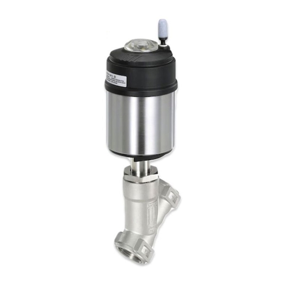
- Seite 1 Type 2100 2/2 and 2/3-way angle seat valve 2/2- und 2/3-Wege-Schrägsitzventil Vanne à siège incliné 2/2 et 2/3 voies Quickstart English - Deutsch - Français...
- Seite 2 We reserve the right to make technical changes without notice. Technische Änderungen vorbehalten. Sous réserve de modifications techniques. © Bürkert Werke GmbH & Co. KG, 2013-2020 Operating Instructions 2008/06_EUml_ 00810247 / Original DE...
-
Seite 3: Inhaltsverzeichnis
Type 2100 Contents Installing valve body ............. 14 CONTENTS Installing devices with welded connection .... 14 1 About these instructions............ 4 Installing control unit ............ 16 Symbols ................. 4 Turning actuator ............ 16 Definition of terms............ 5 Connecting device pneumatically......... 17 2 Intended use................ 5 7 Start-up .................. -
Seite 4: About These Instructions
Type 2100 About these instructions ABOUT THESE WARNING! INSTRUCTIONS Warns of a potentially dangerous situation. The Quickstart contains extremely important information on the ▶ Failure to observe the warning may result in serious or fatal in- device. juries. Keep these instructions ready to hand at the operation site. -
Seite 5: Definition Of Terms
INTENDED USE In these instructions the term "device" denotes the following device types: The angle seat valve Type 2100 is designed to control the flow Angle seat valve Type 2100 rate of media. The permitted media are listed in the "Technical... -
Seite 6: Basic Safety Instructions
Type 2100 Basic safety instructions BASIC SAFETY WARNING! INSTRUCTIONS Risk of injury due to moving parts. These safety instructions do not take into account any unfore- ▶ Do not reach into openings in the device. seen circumstances and events which occur during installation, ▶... - Seite 7 Type 2100 Basic safety instructions To prevent injuries, observe the following: To protect the environment, observe the following: ▶ Secure device or plant to prevent unintentional activation. ▶ The pilot exhaust air of the device may be contaminated by lubricants.
-
Seite 8: General Information
Type 2100 General information GENERAL INFORMATION TECHNICAL DATA Contact address Conformity The device conforms to the EC directives as per the EC Declara- Germany tion of Conformity (if applicable). Bürkert Fluid Control Systems Sales Center Standards Christian-Bürkert-Str. 13−17 The applied standards, which are used to demonstrate conform-... -
Seite 9: Type Label
Control function Permitted medium Operating conditions temperature Type Degree of protection IP67 according to IEC 529 / DIN EN 2100 A PTFE Kv40 60529 PS 16bar Tmed -10°C - +185°C Made in Germany Flow media Water, alcohols, oils, fuels, hydraulic... -
Seite 10: Temperature Ranges
Type 2100 Technical data Usage limits of the armature 5.4.1 Temperature ranges Medium Temperature [°C] Pressure (bar) −10 … +50 25.0 Actuator size Actuator ma- Medium tem- Ambient tem- [mm] terial perature (for perature [°C] 24.5 PTFE seal) 22.4 [°C] 20.3... - Seite 11 Type 2100 Technical data Usage limits of medium and ambient temperature Temperature [°C] Pressure (bar) −10 … +50 14.0 14.0 13.4 12.4 11.7 Tab. 7: Derating the medium pressure as per JIS B 2220 10K 80 100 120 140 160 180 200 220 Medium temperature [°C] Fig. 2: Derating ELEMENT ANTG 50 70, 90...
-
Seite 12: Pressure Ranges
Type 2100 Technical data Required minimum control pressure with control function A : 5.4.2 Pressure ranges depending on medium pressure Actuator size [mm] Maximum pilot pressure [bar] The pressure graphs can be found in the operating in- ø50 structions on the Internet at http://www.burkert.com... -
Seite 13: Installation
Type 2100 Installation INSTALLATION WARNING! Risk of injury due to moving parts. Safety instructions installation ▶ Do not reach into openings in the device. DANGER! ▶ Operate 3-position actuator with transparent cap only. Risk of injury from high pressure and discharge of medium. -
Seite 14: Preparatory Work
Type 2100 Installation Installing devices with welded DANGER! connection Risk of injury from rupturing lines and device when flow direc- ATTENTION! tion above the seat. Damage to the actuator when welding the valve body into the A pressure surge of liquid media may cause the lines and device pipeline. - Seite 15 Type 2100 Installation Place a suitable open-end wrench on the wrench flat of the ATTENTION! body connection. Damage to the valve seat seal or seat contour. Unscrew actuator from the valve body. ▶ When removing the actuator, the valve must be in the open position.
-
Seite 16: Installing Control Unit
Type 2100 Installation ATTENTION! Turning actuator Damage to the valve seat seal or seat contour. 6.6.1 Turning the actuator, devices with ▶ When installing the actuator, the valve must be in the open hexagon nut position. The following description applies only to devices with a For control function A pressurise the pilot air port 1 with com- hexagon head on the actuator. -
Seite 17: Connecting Device Pneumatically
Type 2100 Installation Clamp valve body in a holding device (only for valves which have not yet been installed). ATTENTION! Damage to the seat seal or seat contour. ▶ When turning the actuator, the valve must be in the open pos- ition. - Seite 18 Type 2100 Installation Control function A and B: DANGER! Connect control medium to pilot air port 1 of the actuator. For control function I: Danger due to the control pressure fail- Control function A, 3-position actuator: ing. Connect control medium to pilot air port 1 and 2 of the actu- If the control pressure fails, the valve remains in an undefined ator.
-
Seite 19: Start-Up
Type 2100 Start-up START-UP Exhaust Transparent WARNING! Lock nut Risk of injury from high pressure or hot medium. Excessively high pressure or temperatures may damage the Position of the nut device and cause leaks. 0 % stroke ▶ Observe values for pressure and medium temperature indic- 100 % stroke ated on the type label. -
Seite 20: Deinstallation
Type 2100 Deinstallation Actuator size Seat size Dimension H Total stroke DEINSTALLATION [mm] ±0.3 [mm] [mm] DANGER! ø50 10.4 10.8 Risk of injury from high pressure and discharge of medium. 14.8 ▶ Before working on the device or system, switch off the pres- 18.8... -
Seite 21: Transportation, Storage, Disposal
Type 2100 Transportation, storage, disposal TRANSPORTATION, STORAGE, DISPOSAL ATTENTION! Damage in transit due to inadequately protected devices. ▶ Protect the device against moisture and dirt in shock-resistant packaging during transportation. ▶ Observe permitted storage temperature. ATTENTION! Incorrect storage may damage the device. - Seite 22 Typ 2100 Inhaltsverzeichnis Ventilgehäuse montieren .......... 33 INHALTSVERZEICHNIS Geräte mit Schweißanschluss montieren ..... 33 1 Zu dieser Anleitung .............. 23 Ansteuerung installieren .......... 35 Darstellungsmittel ............ 23 Antrieb drehen .............. 35 Begriffsdefinition ............ 23 Gerät pneumatisch anschließen ........ 37 2 Bestimmungsgemäße Verwendung ........ 24 7 Inbetriebnahme.............. 38 3 Grundlegende Sicherheitshinweise........
-
Seite 23: Zu Dieser Anleitung
Folge. In dieser Anleitung bezeichnet der Begriff "Gerät" folgende Gerätetypen: WARNUNG! Schrägsitzventil Typ 2100 Warnt vor einer möglicherweise gefährlichen Situation. Die in dieser Anleitung verwendete Abkürzung "Ex" steht immer ▶ Bei Nichtbeachten drohen schwere Verletzungen oder Tod. für "explosionsgefährdeter Bereich". -
Seite 24: Bestimmungsgemäße Verwendung
BESTIMMUNGSGEMÄSSE Luftfeuchtigkeit, Dämpfe). Wenden Sie sich bei Fragen an Ihre VERWENDUNG Bürkert Vertriebsniederlassung. GRUNDLEGENDE Das Schrägsitzventil Typ 2100 ist zur Steuerung des Durchflus- ses von Medien konzipiert. Die zulässigen Medien sind in den SICHERHEITSHINWEISE "Technische Daten [} 27]" aufgeführt. Diese Sicherheitshinweise berücksichtigen keine bei Installation, ▶... - Seite 25 Typ 2100 Grundlegende Sicherheitshinweise GEFAHR! WARNUNG! Stromschlag durch angebaute elektrische Komponente. Gefahr durch laute Geräusche. ▶ Vor Arbeiten an Gerät oder Anlage die Spannung abschalten. Abhängig von den Einsatzbedingungen können durch das Gerät Gegen Wiedereinschalten sichern. laute Geräusche entstehen. Genauere Informationen zur Wahr- ▶...
- Seite 26 Typ 2100 Grundlegende Sicherheitshinweise Zum Schutz vor Verletzungen beachten: Zum Schutz der Umgebung beachten: ▶ Gerät oder Anlage gegen ungewolltes Einschalten sichern. ▶ Die Steuerabluft des Geräts kann durch Schmierstoffe verun- reinigt sein. ▶ Nur geschultes Fachpersonal darf Installationsarbeiten und In- standhaltungsarbeiten ausführen.
-
Seite 27: Allgemeine Hinweise
Typ 2100 Allgemeine Hinweise ALLGEMEINE HINWEISE TECHNISCHE DATEN Kontaktadresse Konformität Das Gerät ist konform zu den EU-Richtlinien entsprechend der Deutschland EU-Konformitätserklärung (wenn anwendbar). Bürkert Fluid Control Systems Sales Center Normen Christian-Bürkert-Str. 13−17 Die angewandten Normen, mit welchen die Konformität zu den D-74653 Ingelfingen Richtlinien nachgewiesen wird, sind in der EU-Baumusterprüfbe-... -
Seite 28: Typschild
Tab. 2: Bezeichnung der Antriebsgröße Steuerfunktion zulässige Betriebsbedingungen Mediumstemperatur Schutzart IP67 nach IEC 529 / DIN EN 60529 2100 A PTFE Kv40 Durchflussmedien Wasser, Alkohole, Öle, Treibstoffe, Hy- PS 16bar Tmed -10°C - +185°C Made in Germany draulikflüssigkeiten, Salzlösungen, Lau- Flow 1... -
Seite 29: Temperaturbereiche
Typ 2100 Technische Daten Einsatzgrenzen der Armatur 5.4.1 Temperaturbereiche Medium Temperatur [°C] Druck [bar] −10...+50 25,0 Antriebsgröße Antriebswerk- Mediumstem- Umgebung- [mm] stoff peratur (bei stemperatur 24,5 PTFE-Dich- [°C] 22,4 tung) [°C] 20,3 ø 50 −10...+230 0...+60 19,0 0...+100 ø 70 Tab. 5: Derating des Mediumsdrucks nach DIN EN 12516-1 /... - Seite 30 Typ 2100 Technische Daten Einsatzgrenzen Mediums- und Umgebungstemperatur Temperatur [°C] Druck [bar] −10...+50 14,0 14,0 13,4 12,4 11,7 Tab. 7: Derating des Mediumsdrucks nach JIS B 2220 10K 80 100 120 140 160 180 200 220 Mediumstemperatur [°C] Abb. 2: Derating ELEMENT ANTG 50 70, 90...
-
Seite 31: Druckbereiche
Typ 2100 Technische Daten Erforderlicher Mindeststeuerdruck bei Steuerfunktion A : 5.4.2 Druckbereiche abhängig vom Mediumsdruck Antriebsgröße [mm] Maximaler Steuerdruck [bar] Die Druckdiagramme finden Sie in der Bedienungs- ø50 anleitung im Internet unter http://www.burkert.com ø70 ø90 Mechanische Daten ø130 Antriebsgröße siehe Typschild Tab. 8: Maximaler Steuerdruck... -
Seite 32: Installation
Typ 2100 Installation INSTALLATION WARNUNG! Verletzungsgefahr durch sich bewegende Teile. Sicherheitshinweise Installation ▶ Nicht in Öffnungen des Geräts fassen. GEFAHR! ▶ 3-Stellungs-Antrieb nur mit Klarsichthaube betreiben. Verletzungsgefahr durch hohen Druck und Mediumsaustritt. VORSICHT! ▶ Vor Arbeiten an Gerät oder Anlage den Druck abschalten. Lei- tungen entlüften oder entleeren. -
Seite 33: Vorbereitende Arbeiten
Typ 2100 Installation Geräte mit Schweißanschluss GEFAHR! montieren Verletzungsgefahr durch berstende Leitungen und berstendes ACHTUNG! Gerät bei Anströmung über Sitz. Beschädigung des Antriebs beim Schweißen des Ventilgehäu- Bei flüssigen Medien kann ein Schließschlag zum Bersten von ses in die Rohrleitung. -
Seite 34: Antrieb Auf Ventilgehäuse Montieren
Typ 2100 Installation An der Schlüsselfläche der Gehäuseanbindung mit passen- ACHTUNG! dem Gabelschlüssel ansetzen. Beschädigung der Ventilsitzdichtung oder Sitzkontur. Antrieb vom Ventilgehäuse abschrauben. ▶ Bei der Demontage des Antriebs muss sich das Ventil in ge- öffneter Stellung befinden. 6.4.3 Antrieb auf Ventilgehäuse... -
Seite 35: Ansteuerung Installieren
Typ 2100 Installation Gewinde der Gehäuseanbindung vor dem Wiedereinbau ein- Ansteuerung installieren fetten (z. B. mit Klüberpaste UH1 96-402 der Fa. Klüber). Beschreibung siehe Kapitel "Installation" in der ACHTUNG! Bedienungsanleitung der entsprechenden Ansteuerung. Beschädigung der Ventilsitzdichtung oder Sitzkontur. ▶ Bei der Installation des Antriebs muss sich das Ventil in geöff- Antrieb drehen neter Stellung befinden. - Seite 36 Typ 2100 Installation Für Geräte mit Ansteuerung und Pilotventil: Gerät manuell mit Pilotventil schalten (siehe Bedienungsanleitung der Ansteue- rung). An der Schlüsselfläche der Gehäuseanbindung mit passen- dem Gabelschlüssel gegenhalten. Passenden Gabelschlüssel am Sechskant des Antriebs anset- Antrieb zen. Schlüsselkontur GEFAHR! Gehäuseanbindung...
-
Seite 37: Gerät Pneumatisch Anschließen
Typ 2100 Installation Für Geräte mit Ansteuerung die Bedienungsanleitung der entsprechenden Ansteuerung beachten. 6.7.1 Steuermedium anschließen Die Position der Anschlüsse kann durch Verdrehen des Antriebs stufenlos um 360° ausgerichtet werden. Die Vor- gehensweise ist im Kapitel "Antrieb drehen" beschrieben. Entlüftungsanschluss... -
Seite 38: Inbetriebnahme
Typ 2100 Inbetriebnahme Steuerfunktion I: INBETRIEBNAHME Steuermedium an Steuerluftanschluss 1 und 2 des Antriebs WARNUNG! anschließen. Druck am Steuerluftanschluss 1: Ventil öffnet. Verletzungsgefahr durch hohen Druck oder heißes Medium. Druck am Steuerluftanschluss 2: Ventil schließt. Zu hoher Druck oder zu hohe Temperaturen können das Gerät Schalldämpfer... - Seite 39 Typ 2100 Inbetriebnahme Um die Mittelstellung auf 50 % des Gesamthubs zu begrenzen, ist an den Muttern Maß H einzustellen. Entlüftung Klarsichthaube Antriebsgröße Sitzgröße Maß H ±0,3 Hub gesamt Kontermutter [mm] [mm] [mm] Mutter Position der Mutter ø50 10,4 10,8...
-
Seite 40: Deinstallation
Typ 2100 Deinstallation DEINSTALLATION TRANSPORT, LAGERUNG, ENTSORGUNG GEFAHR! ACHTUNG! Verletzungsgefahr durch hohen Druck und Mediumsaustritt. ▶ Vor Arbeiten an Gerät oder Anlage den Druck abschalten. Lei- Transportschäden bei unzureichend geschützten Geräten. tungen entlüften oder entleeren. ▶ Gerät vor Nässe und Schmutz geschützt in einer stoßfesten Verpackung transportieren. - Seite 41 Type 2100 Table des matières Monter le corps de vanne.......... 52 TABLE DES MATIÈRES Montage d’appareils avec raccord soudé .... 52 1 Concernant le présent manuel .......... 42 Installation de l’unité de commande...... 54 Symboles .............. 42 Tourner l'actionneur............ 55 Définition des termes ........... 43 Raccorder pneumatiquement l’appareil ....... 56...
-
Seite 42: Concernant Le Présent Manuel
Type 2100 Concernant le présent manuel CONCERNANT LE PRÉSENT AVERTISSEMENT ! MANUEL Met en garde contre une situation potentiellement dange- Le Quickstart contient les informations les plus importantes sur reuse. l'appareil. ▶ Le non-respect peut entraîner la mort ou de graves blessures. -
Seite 43: Définition Des Termes
UTILISATION CONFORME Dans le présent manuel d'utilisation, le terme « appareil » désigne les types d'appareil suivants : La vanne à siège incliné type 2100 est conçue pour piloter le Vanne à siège incliné type 2100 débit volumique de fluides. Les fluides autorisés sont indiqués L'abréviation « Ex »... -
Seite 44: Consignes De Sécurité Fondamentales
Type 2100 Consignes de sécurité fondamentales ▶ Protéger l’appareil des influences environnementales nocives AVERTISSEMENT ! (par ex. rayonnement, humidité de l’air, vapeurs etc.). En cas Risque de blessures à l'ouverture de l'actionneur. de questions, veuillez contacter votre distributeur Bürkert. L'actionneur contient un ressort tendu. À l’ouverture de l’action- neur, le ressort qui se détend peut causer des blessures. - Seite 45 Type 2100 Consignes de sécurité fondamentales ▶ Après interruption du processus, garantir une remise en AVERTISSEMENT ! marche contrôlée. Danger en raison de bruits forts. Respecter l'ordre : 1. Établir l’alimentation électrique ou pneumatique. En fonction des conditions d’utilisation, l’appareil peut produire 2.
-
Seite 46: Indications Générales
Type 2100 Indications générales INDICATIONS GÉNÉRALES CARACTÉRISTIQUES TECHNIQUES Adresse de contact Conformité Allemagne L'appareil est conforme aux directives européennes et à la décla- Bürkert Fluid Control Systems ration de conformité UE (si applicable). Sales Center Christian-Bürkert-Str. 13−17 Normes D-74653 Ingelfingen Les normes appliquées, par le biais desquelles la conformité... -
Seite 47: Plaque Signalétique
Température du Conditions d'exploitation fluide admissible Type Degré de protection IP67 selon CEI 529 / DIN EN 60529 2100 A PTFE Kv40 Fluides transportés Eau, alcools, carburants, fluides hy- PS 16bar Tmed -10°C - +185°C Made in Germany drauliques, solutions salines, lessives... -
Seite 48: Plages De Température
Type 2100 Caractéristiques techniques Limites d'utilisation de la vanne 5.4.1 Plages de température Fluide Température [°C] Pression [bar] −10 à +50 25,0 Taille d'action- Matériau de Température Température neur [mm] l’actionneur du fluide (avec ambiante [°C] 24,5 joint PTFE) 22,4 [°C]... - Seite 49 Type 2100 Caractéristiques techniques Limites d’utilisation température du fluide et ambiante Température [°C] Pression [bar] −10 à +50 14,0 14,0 13,4 12,4 11,7 Tab. 7: Perte de débit de la pression du fluide selon JIS B 2220 80 100 120 140 160 180 200 220 Température du fluide [°C]...
-
Seite 50: Caractéristiques Mécaniques
Type 2100 Caractéristiques techniques Pression de pilotage minimale avec arrivée du fluide sur le 5.4.2 Plages de pression siège Taille d'actionneur [mm] Pression de pilotage maximale (flux de fluide dans le sens de fermeture de la vanne) [bar] Pression de pilotage minimale requise avec fonction A: ø50... -
Seite 51: Installation
Type 2100 Installation INSTALLATION DANGER ! Avec la fonction de commande I : danger en cas de panne de Consignes de sécurité relatives à la pression de commande. l’installation En cas de panne de la pression de commande, la vanne s'im- DANGER ! mobilise dans une position indéfinie. -
Seite 52: Activités De Préparation
Type 2100 Installation Selon DIN EN 161 « Vannes d'arrêt automatiques pour brûleurs et AVERTISSEMENT ! appareils à gaz », un filtre doit être monté en amont de la vanne, lequel empêche la pénétration d'un mandrin de contrôle de 1 Siège de vanne non étanche en cas de pression de com- mande trop faible ou de pression de fluide trop élevée. - Seite 53 Type 2100 Installation Appareils avec collet 6.4.2 Démonter l’actionneur du corps de vanne sur les appareils avec unité de REMARQUE ! commande montée Endommagement du joint de siège ou du contour de siège. Serrer le corps de vanne dans un dispositif de fixation.
-
Seite 54: Installation De L'unité De Commande
Type 2100 Installation REMARQUE ! 6.4.3 Montez l'actionneur sur le corps de vanne Endommagement du joint de siège ou du contour de siège. ▶ Lors de l’installation de l'actionneur, la vanne doit être en po- sition ouverte. Joint Avec la fonction A, alimenter le raccord d’air de pilotage 1 en air comprimé... -
Seite 55: Tourner L'actionneur
Type 2100 Installation Serrer le corps de vanne dans un dispositif de fixation (unique- Tourner l'actionneur ment si la vanne n'est pas encore montée). 6.6.1 Tourner l’actionneur, appareils avec REMARQUE ! écrou hexagonal Joint de siège ou contour de siège endommagé. -
Seite 56: Raccorder Pneumatiquement L'appareil
Type 2100 Installation Tourner l’actionneur dans le sens contraire des aiguilles DANGER ! d'une montre (vu d'en bas) pour l’amener dans la position souhaitée. Avec la fonction de commande I : danger en cas de panne de la pression de commande. -
Seite 57: Mise En Service
Type 2100 Mise en service Fonctions A et B : MISE EN SERVICE raccorder le fluide de commande au raccord d’air de pilo- AVERTISSEMENT ! tage 1 de l’actionneur. Risque de blessures dû à la pression élevée et au fluide à... - Seite 58 Type 2100 Mise en service Pour limiter la position médiane à 50 % de la course totale, régler la cote H aux écrous. Purge d'air Capot transparent Taille d'action- Taille de siège Cote H ±0,3 Course totale Contre-écrou neur [mm] [mm] [mm] Écrou Position de l’écrou...
-
Seite 59: Désinstallation
Type 2100 Désinstallation DÉSINSTALLATION TRANSPORT, STOCKAGE, ÉLIMINATION DANGER ! REMARQUE ! Risque de blessure dû à une pression élevée et à la sortie de fluide. Dommages pendant le transport dus à une protection insuffi- sante des appareils. ▶ Couper la pression avant d'intervenir dans l'installation ou l'appareil. - Seite 64 www.burkert.com...