Herunterladen Inhalt Inhalt Diese Seite drucken
AFRISO RG 210 Betriebsanleitung

AFRISO RG 210 Betriebsanleitung

Füllstandregler
Vorschau ausblenden Andere Handbücher für RG 210:

Werbung

Verfügbare Sprachen

Verfügbare Sprachen

Betriebsanleitung
Füllstandregler
Version: 02.2021.0
ID: 900.000.0149
Copyright 2021 AFRISO-EURO-INDEX GmbH. Alle Rechte vorbehalten.
Typ: RG 210
Nur für Fachbetriebe
Lindenstraße 20
74363 Güglingen
Telefon +49 7135 102-0
Service +49 7135 102-211
Telefax +49 7135 102-147
info@afriso.com
www.afriso.com

Werbung

Inhaltsverzeichnis
loading

Inhaltszusammenfassung für AFRISO RG 210

  • Seite 1 Betriebsanleitung Füllstandregler Typ: RG 210 Nur für Fachbetriebe Copyright 2021 AFRISO-EURO-INDEX GmbH. Alle Rechte vorbehalten. Lindenstraße 20 74363 Güglingen Telefon +49 7135 102-0 Service +49 7135 102-211 Telefax +49 7135 102-147 info@afriso.com Version: 02.2021.0 www.afriso.com ID: 900.000.0149...
  • Seite 2 Über diese Betriebsanleitung Über diese Betriebsanleitung Diese Betriebsanleitung beschreibt den Füllstandregler RG 210 (im Folgen- den auch „Produkt“). Diese Betriebsanleitung ist Teil des Produkts. • Sie dürfen das Produkt erst benutzen, wenn Sie die Betriebsanleitung vollständig gelesen und verstanden haben.
  • Seite 3: Informationen Zur Sicherheit

    WARNUNG macht auf eine möglicherweise gefährliche Situation aufmerk- sam, die bei Nichtbeachtung einen schweren oder tödlichen Unfall oder Sachschäden zur Folge haben kann. HINWEIS HINWEIS macht auf eine möglicherweise gefährliche Situation aufmerksam, die bei Nichtbeachtung Sachschäden zur Folge haben kann. RG 210...
  • Seite 4 Sie alle im Zusammenhang mit diesem Warnsymbol beschriebenen Hinweise, um Unfälle mit Todesfolge, Verlet- zungen und Sachschäden zu vermeiden. Dieses Symbol warnt vor gefährlicher elektrischer Span- nung. Wenn dieses Symbol in einem Warnhinweis gezeigt wird, besteht die Gefahr eines elektrischen Schlags. RG 210...
  • Seite 5 Führen Sie bei der Verwendung des Produkts alle Arbeiten ausschließlich unter den in der Betriebsanleitung und auf dem Typenschild spezifizierten Bedingungen und innerhalb der spezifizierten technischen Daten und in Übereinstimmung mit allen am Einsatzort geltenden Bestimmungen, Nor- men und Sicherheitsvorschriften durch. RG 210...
  • Seite 6 Einsatz als Überfüllsicherung • Explosionsgefährdete Umgebung - Bei Betrieb in explosionsgefährdeten Bereichen kann Funkenbildung zu Verpuffungen, Brand oder Explosionen führen. Die Kaltleitersonde Typ 937 darf insbesondere in folgenden Fällen nicht ver- wendet werden: • Einsatz in korrosiven Medien RG 210...
  • Seite 7 über eine entsprechende Zertifizierung verfügt und folgende Anforderun- gen erfüllt: • Einhaltung aller am Einsatzort des Produkts geltenden Bestimmungen, Normen und Sicherheitsvorschriften zum Umgang mit wassergefährdenden Stoffen. • In Deutschland: Zertifizierung gemäß § 62 der Verordnung über Anlagen zum Umgang mit wassergefährdenden Stoffen (AwSV). RG 210...
  • Seite 8 Gefährdungen auftreten können, die nicht direkt vom Produkt ausge- hen. Veränderungen am Produkt Führen Sie ausschließlich solche Arbeiten an und mit dem Produkt durch, die in dieser Betriebsanleitung beschrieben sind. Nehmen Sie keine Verände- rungen vor, die in dieser Betriebsanleitung nicht beschrieben sind. RG 210...
  • Seite 9: Transport Und Lagerung

    Benutzen Sie für den Transport die Originalverpackung. • Lagern Sie das Produkt nur in trockener, sauberer Umgebung. • Stellen Sie sicher, dass das Produkt bei Transport und Lagerung stoßge- schützt ist. Nichtbeachtung dieser Anweisungen kann zu Sachschäden führen. RG 210...
  • Seite 10: Produktbeschreibung

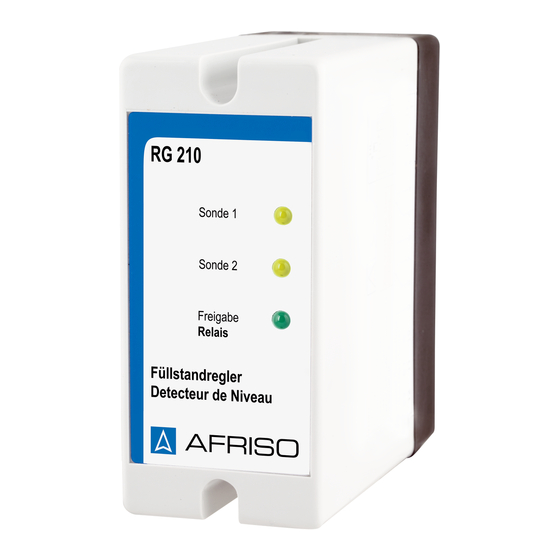
    Umformung des Sondensignals in ein digitales Ausgangssignal. Das Ausgangssignal steht als potenzialfreier Relaiskontakt (Wechsler) zur Verfügung. A. Gelbe LED „Sonde 1“ und „Sonde 2“ B. Grüne LED  „Freigabe Relais“ C. Gehäuseoberteil D. Sockel Abbildung 1: Füllstandregler RG 210...
  • Seite 11 Die Kaltleitersonde ist ein Verschleißteil. Sie muss spätestens nach zehn Jahren erneuert werden.  A. Einschraubkörper G½ oder G1 B. Sondenkabel C. Messinggewicht D. Schutzhülse über dem Kaltleiter E. Kaltleiter F. Schaltpunkt (Markierung) Abbildung 2: Kaltleitersonde Typ 937 RG 210...
  • Seite 12 Produktbeschreibung Abmessungen 53 mm RG 210...
  • Seite 13 Produktbeschreibung Anwendungsbeispiel(e) A. Pumpe Stopp C. Sonde 1 B. RG 210 D. Maximaler Füllstand Abbildung 3: Einsatz als Füllstandgrenzschalter RG 210...
  • Seite 14 Produktbeschreibung A. Pumpe an/aus D. Sonde 2 B. RG 210 E. Maximaler Füllstand C. Sonde 1 F. Minimaler Füllstand Abbildung 4: Einsatz als Füll-/Entnahmesteuerung Lieferumfang Im Lieferumfang sind enthalten: • Füllstandregler RG 210 RG 210...
  • Seite 15 Wenn sich beide Sonden in einer Flüssigkeit befinden, leuchtet die grüne LED. Wenn sich eine der Sonden in der Luft befindet, geht die gelbe LED der betroffenen Sonde an. Wenn sich beide Sonden in der Luft befinden, ist die grüne LED aus. RG 210...
  • Seite 16 Das Produkt kann mit und ohne Zusatzgeräte betrieben werden, beispiels- weise: • Optische und akustische Alarmgeber • Fernmeldegeräte • Gebäudeleittechnik • Pumpen • Ventile Zulassungsdokumente, Bescheinigungen, Erklärungen Das Produkt entspricht: • EMV-Richtlinie (2014/30/EU) • Niederspannungsrichtlinie (2014/35/EU) • RoHS-Richtlinie (2011/65/EU) RG 210...
  • Seite 17 Nennleistung Max. 12 VA Netzsicherung M 100 mA (5 x 20 mm) Schaltvermögen Ausgangrelais Max. 250 V, 2 A Elektrische Sicherheit (EN 61010) Schutzklasse (EN 60730) Schutzart IP 30 Elektromagnetische Verträglichkeit (EMV) Störaussendung EN 61000-6-3 Störfestigkeit EN 61000-6-1 RG 210...
  • Seite 18 8 ... 30 s, siehe Kapitel "Montage vorbereiten" Umgebungsbedingungen Umgebungstemperatur Betrieb -25 ... 75 °C Umgebungstemperatur Medium -25 ... 50 °C Umgebungstemperatur Lagerung -25 ... 75 °C Elektrische Daten Sondenspannung Max. DC 12 V Elektrische Sicherheit Schutzart (EN 60529) IP 68 RG 210...
  • Seite 19: Montage

    Wand in Augenhöhe montiert wird.  Stellen Sie sicher, dass die zulässige Umgebungstemperatur am Produkt eingehalten wird.  Stellen Sie sicher, dass das Produkt jederzeit zugänglich und einsehbar ist.  Stellen Sie sicher, dass das Produkt vor Wasser und Spritzwasser geschützt ist. RG 210...
  • Seite 20 5. Stellen Sie die Betriebsart ein, siehe Kapitel "Betriebsart einstellen". 6. Setzen Sie das Gehäuseoberteil auf den Sockel. - Stellen Sie sicher, dass die Kontaktleiste der Leiterplatte die Kontakt- federn des Sockels nicht verbiegt. 7. Schrauben Sie das Gehäuseoberteil fest. RG 210...
  • Seite 21: Beschädigung Der Anlage

    2. Ziehen Sie das Kabelende der Sonde durch das Gewicht und den Ein- schraubkörper. 3. Stecken Sie die Kaltleitersonde mit Gewicht durch die Bohrung. 4. Schrauben Sie den Einschraubkörper G1 am Behälter ein. 5. Befestigen Sie das Kabel der Kaltleitersonde in der Höhe des gewünschten Schaltpunktes. RG 210...
  • Seite 22: Elektrischer Schlag

    HINWEIS NICHTVERFÜGBARKEIT DER ÜBERWACHUNGSFUNKTION • Installieren Sie keine Netzstecker oder Schalter in der Spannungsversor- gung für das Produkt. • Schalten Sie das Produkt nur über die bauseitige Netzsicherung ein und aus. Nichtbeachtung dieser Anweisungen kann zu Sachschäden führen. RG 210...
  • Seite 23 16 A abgesichert ist. 1. Führen Sie das Netzkabel durch die obere Gummitülle in das Produkt. 2. Schließen Sie die Phase an die Klemme L1 an. 3. Klemmen Sie N an. 4. Schließen Sie den Schutzleiter an die Klemme PE an. RG 210...
  • Seite 24 Montage  A. Freigabe D. Anschlussbild im Gehäuse B. Sonde 1 E. Pumpe C. Sonde 2 RG 210...
  • Seite 25: Spannungsspitzen Beim Abschalten Induktiver Verbraucher

    Nichtbeachtung dieser Anweisungen kann zu Sachschäden führen. 1. Verlegen Sie das Signalkabel fest. 2. Führen Sie das Signalkabel durch die mittlere Gummitülle in den schwarzen Sockel. 3. Schließen Sie das Signalkabel an die entsprechenden Klemmen mit der Bezeichnung "Freigabe" an. RG 210...
  • Seite 26 1. Lösen Sie mit einem kleinen Schraubendreher die graue Abdeckscheibe aus dem Gehäuseoberteil. 2. Ziehen Sie die Leiterplatte aus dem Gehäuseoberteil. 3. Schalten Sie mit dem Schiebeschalter (B) die gewünschte Betriebsart ein, siehe Kapitel "Funktion". 4. Setzen Sie die Leiterplatte wieder ein. 5. Schließen Sie das Produkt. RG 210...
  • Seite 27: Betrieb

    Beim Einschalten des Produkts beträgt die Aufheizzeit des Kaltleiters in der Sonde bis zu 15 Sekunden. Erst nach Ablauf der Aufheizzeit ist das Produkt betriebsbereit. Wenn inzwischen der Minimalfüllstand oder der Maximalfüllstand erreicht wurden, gibt das Produkt nach Wiederkehr der Versorgungsspannung Alarm. RG 210...
  • Seite 28: Wartung

    Führen Sie eine Funktionsprüfung durch, siehe Inbetriebnahme oder Kapitel "Funktionsprüfung". nach Reparaturarbeiten Prüfen Sie die Sonde/Sonden auf Beschädigun- gen, Ablagerungen und Verschmutzungen. Tauschen Sie die Sonde/Sonden bei Ablagerun- gen aus. Mindestens alle 10 Erneuern Sie die Sonde/Sonden. Jahre RG 210...
  • Seite 29 6. Schieben Sie die Leiterplatte in das Gehäuseoberteil. 7. Setzen Sie das Gehäuseoberteil auf den Sockel. - Stellen Sie sicher, dass die Kontaktleiste der Leiterplatte die Kontakt- federn des Sockels nicht verbiegt. 8. Schrauben Sie das Gehäuseoberteil fest. 9. Schalten Sie die Netzspannung ein. RG 210...
  • Seite 30: Störungsbeseitigung

    Überprüfen Sie die Betriebs- Relais schaltet nicht eingestellt art, siehe Kapitel "Betriebs- art einstellen" Sonden vertauscht Schließen die Sonden kor- rekt an Produkt defekt Tauschen Sie das Produkt Sonstige Störungen Bitte wenden Sie sich an die AFRISO-Service Hotline RG 210...
  • Seite 31: Außerbetriebnahme Und Entsorgung

    3. Entsorgen Sie das Produkt. Rücksendung Vor einer Rücksendung Ihres Produkts müssen Sie sich mit uns in Verbin- dung setzen(service@afriso.de). Gewährleistung Informationen zur Gewährleistung finden Sie in unseren Allgemeinen Geschäftsbedingungen im Internet unter www.afriso.com oder in Ihrem Kauf- vertrag. RG 210...
  • Seite 32: Ersatzteile Und Zubehör

    Ersatzteile und Zubehör Ersatzteile und Zubehör HINWEIS UNGEEIGNETE TEILE • Verwenden Sie nur Original Ersatz- und Zubehörteile des Herstellers. Nichtbeachtung dieser Anweisung kann zu Sachschäden führen. Produkt Artikelbezeichnung Art.-Nr. Abbildung Füllstandregler 53206 „RG 210“ Kaltleitersonde 53204 Typ 937 RG 210...
  • Seite 33 Operating instructions Level controller Type: RG 210 For specialised companies only Copyright 2021 AFRISO-EURO-INDEX GmbH. All rights reserved. Lindenstraße 20 74363 Güglingen Telephone +49 7135 102-0 Service +49 7135 102-211 Telefax +49 7135 102-147 info@afriso.com Version: 02.2021.0 www.afriso.com ID: 900.000.0149...
  • Seite 34 About these operating instructions About these operating instructions These operating instructions describe the level controller RG 210 (also referred to as "product" in these operating instructions). These operating instructions are part of the product. • You may only use the product if you have fully read and understood these operating instructions.
  • Seite 35: Information On Safety

    This symbol alerts to hazardous electrical voltage. If this symbol is used in a safety message, there is a hazard of electric shock. RG 210...
  • Seite 36 RG 210...
  • Seite 37 Hazardous area (EX) - If the product is operated in hazardous areas, sparks may cause defla- grations, fires or explosions. The PTC thermistor probe type 937 must never be used in the following cases: • Use with corrosive media RG 210...
  • Seite 38 • In Germany: Certification as per § 62 "Verordnung über Anlagen zum Umgang mit wassergefährdenden Stoffen" (AwSV) (Ordinance on Installa- tions for Handling Water-Polluting Substances). RG 210...
  • Seite 39 Modifications to the product Only perform work on and with the product which is explicitly described in these operating instructions. Do not make any modifications to the product which are not described in these operating instructions. RG 210...
  • Seite 40: Transport And Storage

    Use the original packaging when transporting the product. • Store the product in a clean and dry environment. • Verify that the product is protected against shocks and impact during trans- port and storage. Failure to follow these instructions can result in equipment damage. RG 210...
  • Seite 41: Product Description

    The output signal is available as a voltage-free relay contact (changeover contact). A. Yellow LEDs "Probe 1" and "Probe 2" ("Sonde 1" and "Sonde 2") B. Green LED "Release Relay" ("Freigabe Relais") C. Upper part of housing D. Base Fig. 1: Level controllers RG 210...
  • Seite 42 The PTC thermistor probe is a wearing part. It must be replaced after no more than ten years.  A. Screw fitting G½ or G1 B. Probe cable C. Brass weight D. Protective sleeve for PTC thermis- E. PTC thermistor F. Switching point (mark) Fig. 2: PTC thermistor probe type 937 RG 210...
  • Seite 43 Product description Dimensions 53 mm RG 210...
  • Seite 44 Product description Application example(s) A. Pump stop C. Probe 1 B. RG 210 D. Maximum level Fig. 3: Use as level switch RG 210...
  • Seite 45 A. Pump on/off D. Probe 2 B. RG 210 E. Maximum level C. Probe 1 F. Minimum level Fig. 4: Use as level controller for filling/emptying Scope of delivery The scope of delivery includes: • Level controller RG 210 RG 210...
  • Seite 46 If both probes are in a liquid, the green LED is lit. If one of the probes is in air, the yellow LED of this probe is lit. If both probes are in air, the green LED is off. RG 210...
  • Seite 47 • Visual and audible alarm units • Remote alarm equipment • Building control systems • Pumps • Valves Approvals, conformities, certifications The product complies with: • EMC Directive (2014/30/EU) • Low Voltage Directive (2014/35/EU) • RoHS Directive (2011/65/EU) RG 210...
  • Seite 48 M 100 mA (5 x 20 mm) Breaking capacity output relay Max. 250 V, 2 A Electrical safety (EN 61010) Protection class (EN 60730) Degree of protection IP 30 Electromagnetic compatibility (EMC) Emitted interference EN 61000-6-3 Noise immunity EN 61000-6-1 RG 210...
  • Seite 49 Ambient temperature operation -25 ... 75 °C Ambient temperature medium -25 ... 50 °C Ambient temperature storage -25 ... 75 °C Electrical data Probe voltage Max. DC 12 V Electrical safety Degree of protection (EN 60529) IP 68 RG 210...
  • Seite 50  Verify that the permissible ambient temperature is respected at the prod- uct.  Verify that the product is accessible and easy to oversee at all times.  Verify that the product is protected against water and splash water. RG 210...
  • Seite 51 6. Fit the upper part of the housing to the base. - Verify that the contact bar of the printed circuit board does not damage the contact springs of the base. 7. Mount the upper part of the housing with the screws. RG 210...
  • Seite 52 3. Insert the PTC thermistor probe with weight through the hole. 4. Screw in the screw fitting G1 at the container. 5. Fasten the cable of the PTC thermistor probe at the height of the desired switching point. RG 210...
  • Seite 53: Electric Shock

    UNAVAILABLE MONITORING FUNCTION • Do not install mains plugs or switches in the supply line to the product. • Only power on/power off the product via the on-site mains fuse. Failure to follow these instructions can result in equipment damage. RG 210...
  • Seite 54 Verify that the power supply to the control unit is separately fused (16 A maximum). 1. Route the mains cable through the upper rubber piece into the product. 2. Connect the phase to terminal L1. 3. Connect N. 4. Connect the protective conductor to terminal PE. RG 210...
  • Seite 55 Mounting  A. Release D. Wiring diagram in housing B. Probe 1 E. Pump C. Probe 2 RG 210...
  • Seite 56 Failure to follow these instructions can result in equipment damage. 1. The signal cable requires permanent installation. 2. Route the signal cable through the centre rubber piece into the black base. 3. Connect the signal cable to the appropriate terminals with the designa- tion "Freigabe" ("Release"). RG 210...
  • Seite 57 2. Pull the printed circuit board out of the upper part of the housing. 3. Se the desired operating mode with the slide switch (B), see chapter "Function". 4. Refit the printed circuit board. 5. Close the product. RG 210...
  • Seite 58: Operation

    15 seconds. This heat-up time must elapse before the product is ready for operation. If, during the power outage, the minimum level or the maximum level have been reached, the product triggers an alarm once power is available again. RG 210...
  • Seite 59: Maintenance

    Perform a function test, see chapter "Function ing commissioning or test". after after repair work Verify that the probe(s) are free from damage, deposits and pollution. Replace the probe(s) if you detect deposits. At least every 10 years Replace the probe(s). RG 210...
  • Seite 60 7. Fit the upper part of the housing to the base. - Verify that the contact bar of the printed circuit board does not damage the contact springs of the base. 8. Mount the upper part of the housing with the screws. 9. Apply mains voltage. RG 210...
  • Seite 61: Troubleshooting

    Green LED and the incorrect operating Check the operating mode, relay do not switch mode selected see chapter "Setting the operating mode" Probes inter- Properly connect the probes changed Product defective Replace the product Other malfunctions Contact the AFRISO service hotline RG 210...
  • Seite 62: Decommissioning / Disposal

    2. Dismount the product (see chapter "Mounting", reverse sequence of steps). 3. Dispose of the product. Returning the device Get in touch with us before returning your product (service@afriso.de). Warranty See our terms and conditions at www.afriso.com or your purchase contract for information on warranty. RG 210...
  • Seite 63: Spare Parts And Accessories

    Only use genuine spare parts and accessories provided by the manufac- turer. Failure to follow these instructions can result in equipment damage. Product Product designation Part no. Figure Level controller 53206 "RG 210" PTC thermistor probe 53204 type 937 RG 210...
  • Seite 64: Notice Technique

    Notice technique Régulateur de niveau Type : RG 210 Seulement pour les entreprises spécialisées Copyright 2021 AFRISO-EURO-INDEX GmbH. Tous droits réservés. Lindenstraße 20 74363 Güglingen Téléphone +49 7135 102-0 Service clientèle +49 7135 102-211 Téléfax +49 7135 102-147 info@afriso.com Version: 02.2021.0...
  • Seite 65 La présente notice technique La présente notice technique Cette notice technique contient la description du régulateur de niveau RG 210 (dénommé ci-après "produit"). Cette notice technique fait partie du produit. • Utilisez le produit seulement après que vous aurez lu et compris intégra- lement la notice technique.
  • Seite 66: Informations Sur La Sécurité

    AVERTISSEMENT signale une situation potentiellement dangereuse qui, si elle n'est pas évitée, peut entraîner la mort ou des blessures graves ou un dommage matériel. AVIS AVIS signale une situation potentiellement dangereuse qui, si elle n'est pas évitée, peut entraîner un dommage matériel. RG 210...
  • Seite 67 Ce pictogramme avertit d'une tension électrique dange- reuse. Si ce pictogramme s'affiche dans une consigne de sécurité, il y a un risque de choc électrique. RG 210...
  • Seite 68 Pendant l'utilisation du produit effectuez toutes les opérations exclusivement dans les conditions spécifiées dans cette notice technique et sur la plaque signalétique, conformément aux données techniques spécifiées et en accord avec tous les règlements, normes et consignes de sécurité en vigueur sur le lieu d'installation. RG 210...
  • Seite 69 - En cas de service dans des zones à risque d'explosion, des étincelles peuvent provoquer des déflagrations, des incendies ou des explosions. La sonde à thermistance type 937 ne doit, en particulier, pas être utilisée dans les cas suivants : • Utilisation dans les liquides corrosifs RG 210...
  • Seite 70 • En Allemagne : Certification selon l'article 62 de l'ordonnance allemande sur les installations contenant des substances susceptibles de polluer l'eau (AwSV). RG 210...
  • Seite 71 Modification du produit En travaillant sur le produit et avec celui-ci, effectuez exclusivement les opé- rations décrites dans cette notice technique. N'effectuez pas de modifica- tions non décrites dans cette notice technique. RG 210...
  • Seite 72: Transport Et Stockage

    Utilisez l'emballage d'origine pour le transport. • Stockez le produit dans un lieu sec et propre. • Assurez-vous que le produit est à l'abri des chocs pendant le transport et le stockage. La non-observation de ces instructions peut causer des dommages maté- riels. RG 210...
  • Seite 73: Description Du Produit

    Le signal de sortie est disponible en contact relais (contact inverseur) libre de potentiel. A. LED jaunes "Sonde 1" et "Sonde 2" B. LED verte  "Relais" C. Partie supérieure du boîtier D. Embase Figure 1: Régulateur de niveau RG 210...
  • Seite 74  A. Raccord à visser G½ ou G1 B. Câble de sonde C. Poids en laiton D. Tube de protection recouvrant la thermistance E. Thermistance CTP F. Seuil de commutation (repère) Figure 2: Sonde à thermistance Type 937 RG 210...
  • Seite 75 Description du produit Dimensions 53 mm RG 210...
  • Seite 76 Description du produit Exemple(s) d'application A. Pompe arrêt C. Sonde 1 B. RG 210 D. Niveau maximum Figure 3: Utilisation comme interrupteur de niveau RG 210...
  • Seite 77 Description du produit A. Pompe marche/arrêt D. Sonde 2 B. RG 210 E. Niveau maximum C. Sonde 1 F. Niveau minimum Figure 4: Utilisation comme régulateur de remplissage/vidange Composants fournis Composants fournis : • Régulateur de niveau RG 210 RG 210...
  • Seite 78 Si les deux sondes sont dans le liquide, la LED verte est allumée. Si l'une des sondes est dans l'air, la LED jaune de la sonde concernée s'allume. Si les deux sondes sont dans l'air, la LED verte est éteinte. RG 210...
  • Seite 79 Des dispositifs pour les alarmes sonores ou visuelles • Appareils de télécommunication • Equipement pour la gestion de bâtiments • Pompes • Vannes Agréments, certificats, déclarations Le produit est conforme à : • Directive CEM (2014/30/UE) • Directive basse tension (2014/35/UE) • Directive RoHS (2011/65/UE) RG 210...
  • Seite 80 M 100 mA (5 x 20 mm) Pouvoir de coupure relais sortie 250 V max., 2 A Sécurité électrique (EN 61010) Classe de protection (EN 60730) Degré de protection IP 30 Compatibilité électromagnétique (CEM) Émission EN 61000-6-3 Immunité EN 61000-6-1 RG 210...
  • Seite 81 Température ambiante service -25 ... 75 °C Température ambiante fluide -25 ... 50 °C Température ambiante stockage -25 ... 75 °C Données électriques Tension sonde Max. DC 12 V Sécurité électrique Degré de protection (EN 60529) IP 68 RG 210...
  • Seite 82: Montage

    à surface plane.  Assurez-vous que la température ambiante autorisée du produit est res- pectée.  Assurez-vous que le produit est accessible et consultable en tout temps.  Assurez-vous que le produit est protégé contre l'eau ou des projections d'eaux. RG 210...
  • Seite 83 5. Réglez le mode de fonctionnement, voir chapitre "Réglage du mode de fonctionnement". 6. Placez la partie supérieure du boîtier sur l'embase. - Assurez-vous que les contacts de la platine ne provoquent pas des dommages aux ressorts de contact sur l'embase. 7. Vissez la partie supérieure du boîtier. RG 210...
  • Seite 84 3. Faites passer la sonde de thermistance PTC avec le poids à travers le trou. 4. Vissez le raccord à visser G1 dans le récipient. 5. Fixez le câble de la sonde à thermistance CTP à la hauteur du point de commutation souhaité. RG 210...
  • Seite 85: Choc Électrique

    NON DISPONIBILITÉ DE LA FOCNTION DE SURVEILLANCE • N'installez pas des fiches secteur et des commutateurs dans l'alimentation du produit. • Allumez et éteindrez le produit uniquement par l'intermédiaire du fusible sec- teur. La non-observation de ces instructions peut causer des dommages maté- riels. RG 210...
  • Seite 86 (16 A max.). 1. Faites passer le câble secteur par la passe-câble en caoutchouc du haut dans le produit. 2. Branchez la phase à la borne L1. 3. Branchez N. 4. Branchez le conducteur de protection à la borne PE. RG 210...
  • Seite 87 Montage  A. Relais D. Schéma à l'intérieur du boîtier B. Sonde 1 E. Pompe C. Sonde 2 RG 210...
  • Seite 88 1. Montez de manière fixe le câble de signal. 2. Faites passer le câble de signal par la passe-câble en caoutchouc cen- tral dans la base noire. 3. Raccordez le câble de signal aux bornes appropriées avec la désigna- tion "Relais" ("Freigabe"). RG 210...
  • Seite 89: Mise En Service

    1. Démontez le couvercle gris de la partie supérieure du boîtier à l'aide d'un petit tournevis. 2. Retirez la platine de la partie supérieure du boîtier. 3. Réglez le mode de fonctionnement souhaité à l'aide de l'interrupteur cou- lissant (B), voir chapitre "Fonctionnement". 4. Remettez la platine. 5. Fermez le produit. RG 210...
  • Seite 90 Le produit est prêt au service après la durée de chauffage. Si entre-temps le niveau minimal ou le niveau maximal ont été atteints, le pro- duit déclenche une alarme une fois que l'alimentation est à nouveau dispo- nible. RG 210...
  • Seite 91: Maintenance

    "Test de fonctionnement". réparations Vérifiez la sonde/les sondes afin de déceler des dommages, des dépôts et des salissures. Remplacez la sonde/les sondes s'il y a des dépôts. Au moins tous les 10 Remplacez la sonde/les sondes. RG 210...
  • Seite 92 7. Placez la partie supérieure du boîtier sur l'embase. - Assurez-vous que les contacts de la platine ne provoquent pas des dommages aux ressorts de contact sur l'embase. 8. Vissez la partie supérieure du boîtier. 9. Allumez la tension secteur. RG 210...
  • Seite 93: Suppression Des Dérangements

    Vérifiez le mode de fonction- relais ne changent pas nement mal réglé nement, voir chapitre d'état "Réglage du mode de fonc- tionnement" Sondes inverties Branchez correctement les sondes Produit défectueux Remplacez le produit Autre dérangement Veuillez contacter l'AFRISO Service Hotline RG 210...
  • Seite 94: Mise Hors Service Et Élimination

    Retour Avant de retourner le produit, il faut que vous preniez contact avec nous (ser- vice@afriso.de). Garantie Les informations sur la garantie figurent dans nos "Conditions générales de vente" sur le site www.afriso.com ou dans votre contrat d'achat. RG 210...
  • Seite 95: Pièces Détachées Et Accessoires

    N'utilisez que des accessoires et des pièces détachées d'origine provenant du fabricant. La non-observation de ces instructions peut causer des dommages maté- riels. Produit Désignation de l'article Référence Figure Régulateur de niveau  53206 "RG 210" Sonde à thermistance 53204 Type 937 RG 210...

Inhaltsverzeichnis