Inhaltsverzeichnis
Werbung
Verfügbare Sprachen
Verfügbare Sprachen
Quicklinks
Betriebsanleitung
Heizungspumpengruppe
Version: 11.2019.0
ID: 900.000.0925
Typ: 180-2 DN25 Vario mit verstellbarem Mischer
Typ: 180-3 DN25 Rückl. mit thermischem Mischventil
Copyright 2019 AFRISO-EURO-INDEX GmbH. Alle Rechte vorbehalten.
PrimoTherm®
Typ: 180-1 DN25 ohne Mischer
Typ: 180-2 DN25 mit 3-Wege-Mischer
Lindenstraße 20
74363 Güglingen
Telefon +49 7135 102-0
Service +49 7135 102-211
Telefax +49 7135 102-147
info@afriso.com
www.afriso.com
Werbung
Kapitel
Inhaltsverzeichnis

Verwandte Anleitungen für AFRISO PrimoTherm 180-1 DN25


Inhaltszusammenfassung für AFRISO PrimoTherm 180-1 DN25
- Seite 1 Typ: 180-1 DN25 ohne Mischer Typ: 180-2 DN25 mit 3-Wege-Mischer Typ: 180-2 DN25 Vario mit verstellbarem Mischer Typ: 180-3 DN25 Rückl. mit thermischem Mischventil Copyright 2019 AFRISO-EURO-INDEX GmbH. Alle Rechte vorbehalten. Lindenstraße 20 74363 Güglingen Telefon +49 7135 102-0 Service +49 7135 102-211 Telefax +49 7135 102-147 info@afriso.com...
-
Seite 3: Inhaltsverzeichnis
Über diese Betriebsanleitung ............4 Informationen zur Sicherheit ............5 2.1 Warnhinweise und Gefahrenklassen ...........5 2.2 Bestimmungsgemäße Verwendung ..........6 2.3 Vorhersehbare Fehlanwendung ..........7 2.4 Qualifikation des Personals ............7 2.5 Persönliche Schutzausrüstung ............7 2.6 Veränderungen am Produkt ............7 Transport und Lagerung ..............8 Produktbeschreibung ............... - Seite 4 Störungsbeseitigung ..............28 8.1 Umwälzpumpe tauschen ............28 Außerbetriebnahme und Entsorgung ........... 29 Rücksendung .................. 29 Gewährleistung ................29 PrimoTherm®...
-
Seite 5: Über Diese Betriebsanleitung
Über diese Betriebsanleitung Über diese Betriebsanleitung Diese Betriebsanleitung beschreibt die Heizungspumpengruppen PrimoT- herm® „180-1 DN25“ / „180-2 DN25“ / „180-3 DN25“ (im Folgenden auch „Produkt“). Diese Betriebsanleitung ist Teil des Produkts. • Sie dürfen das Produkt erst benutzen, wenn Sie die Betriebsanleitung vollständig gelesen und verstanden haben. -
Seite 6: Warnhinweise Und Gefahrenklassen
Informationen zur Sicherheit Informationen zur Sicherheit Warnhinweise und Gefahrenklassen In dieser Betriebsanleitung finden Sie Warnhinweise, die auf potenzielle Gefahren und Risiken aufmerksam machen. Zusätzlich zu den Anweisungen in dieser Betriebsanleitung müssen Sie alle am Einsatzort des Produktes gel- tenden Bestimmungen, Normen und Sicherheitsvorschriften beachten. Stel- len Sie vor Verwendung des Produkts sicher, dass Ihnen alle Bestimmungen, Normen und Sicherheitsvorschriften bekannt sind und dass sie befolgt wer- den. -
Seite 7: Informationen Zur Sicherheit
Informationen zur Sicherheit Zusätzlich werden in dieser Betriebsanleitung folgende Symbole verwendet: Dies ist das allgemeine Warnsymbol. Es weist auf die Gefahr von Verletzungen und Sachschäden hin. Befolgen Sie alle im Zusammenhang mit diesem Warnsymbol beschriebenen Hinweise, um Unfälle mit Todesfolge, Verlet- zungen und Sachschäden zu vermeiden. -
Seite 8: Vorhersehbare Fehlanwendung
Informationen zur Sicherheit Vorhersehbare Fehlanwendung Das Produkt darf insbesondere in folgenden Fällen und für folgende Zwecke nicht angewendet werden: • Betrieb mit Trinkwasser • Betrieb mit verklebenden, ätzenden oder entzündlichen Medien • Betrieb in Anlagen mit Temperaturen über 110 °C (beispielsweise Solar- anlagen) •... -
Seite 9: Transport Und Lagerung
Transport und Lagerung Transport und Lagerung Das Produkt kann durch unsachgemäßen Transport und Lagerung beschä- digt werden. HINWEIS UNSACHGEMÄSSE HANDHABUNG • Stellen Sie sicher, dass während des Transports und der Lagerung des Pro- dukts die spezifizierten Umgebungsbedingungen eingehalten werden. • Benutzen Sie für den Transport die Originalverpackung. -
Seite 10: Übersicht
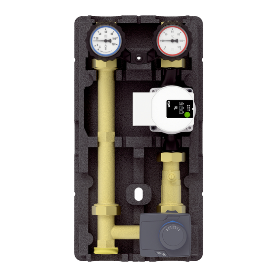
Produktbeschreibung Produktbeschreibung Das Produkt ist eine vormontierte, dichtheitsgeprüfte und wärmegedämmte Heizungspumpengruppe, die den Einbau handelsüblicher Pumpen (mit dem Anschluss G1½ und einer Baulänge von 180 mm) ermöglicht. Der Vorlauf kann wahlweise links oder rechts angeordnet werden. Optional können in allen Kugelhähnen Temperaturfühler montiert werden. Übersicht 1. -
Seite 11: Produktbeschreibung
Produktbeschreibung Abmessungen und Anschlüsse ca. 155 mm ca. 248 mm ca. 196 mm Abbildung 2: PrimoTherm® K kurze Ausführung PrimoTherm®... - Seite 12 Produktbeschreibung ca. 152 mm ca. 250 mm ca. 175 mm Abbildung 3: PrimoTherm® Standardausführung PrimoTherm®...
- Seite 13 Produktbeschreibung A. G1 ca. 60 mm B. G1½ C. G1 1. Anschlussset (optionales Zubehör) ca. 125 mm Abbildung 4: PrimoTherm® Standardausführung mit optionalem Anschlussset PrimoTherm®...
-
Seite 14: Funktion
Produktbeschreibung Funktion Variante 180-2 Stellen Sie bei Verwendung der Variante 180-2 sicher, dass der Mischer- motor von der Kesselsteuerung oder einer anderen Steuerung gesteuert werden kann. 1. Prüfen Sie, ob die Steuerung des verwendeten Kessels über eine Motor- steuerung verfügt. Variante 180-3 Die Variante 180-3 wird bei Festbrennstoffkesseln zur Speicherladung ein- gesetzt. -
Seite 15: Technische Daten
Produktbeschreibung Technische Daten Parameter Wert Allgemeine Daten PrimoTherm PrimoTherm K Abmessungen mit Isolie- 250 x 475 x 152 mm 250 x 400 x 196 mm rung (B x H x T) Gewicht 180-2 DN 25 Ca. 5,5 kg Ca. 3,0 kg ohne Umwälzpumpe Werkstoff Armaturen Messing, Stahl, Kunststoffe... -
Seite 16: Montage
Montage Montage Falls nicht anders angegeben, beziehen sich alle Angaben zur Montage auf die Einbauweise Vorlauf rechts. Der Umbau ist in Kapitel “Vorlauf/Rücklauf tauschen” auf Seite 20 beschrieben. Montage vorbereiten Das Produkt darf erst nach Abschluss aller Rohrmontagearbeiten, Schweiß- und Lötarbeiten montiert werden. •... -
Seite 17: Einstellwert Kvs Bestimmen
Montage Einstellwert Kvs bestimmen Der Einstellwert Kvs für die Blende wird anhand der Leistung des Heizkreises (KW) und der Temperaturspreizung zwischen Vor- und Rücklauf (K ent- spricht °C) bestimmt; siehe nachfolgende Tabelle. Beispiel: A. Leistung: 20 KW B. Temperaturspreizung: 20 K -> 20 °C C. -
Seite 18: Einstellwert Kvs Einstellen
Montage Einstellwert Kvs einstellen 1. Stellen Sie den Einstellwert Kvs mit einem Schraubendreher ein. 2. Beachten Sie die Durch- flussrichtung. - Die Ziffern müssen rich- tig herum lesbar sein. Alternative, wenn der Mischer bereits eingebaut ist: 1. Stellen Sie den Einstellwert Kvs an der Skala ein. -
Seite 19: Produkt Montieren
Montage Produkt montieren HINWEIS MECHANISCHE BELASTUNG UND VERSPANNUNG • Stellen Sie beim Anschließen des Produkts sicher, dass das Produkt keinen mechanischen Belastungen und Verspannungen ausgesetzt ist. • Bauen Sie, wenn erforderlich, einen Wellrohrkompensator ein, um mechani- sche Belastungen und Verspannungen zu kompensieren. Nichtbeachtung dieser Anweisungen kann zu Sachschäden führen. -
Seite 20: 2Wandmontage
Montage 5.5.2 Wandmontage Stellen Sie sicher, dass die beigelegten Dübel für die vorgesehene Wand geeignet sind. 1. Prüfen Sie die Tragfähigkeit der Wand. 2. Entfernen Sie die obere Isolie- rung. 3. Halten Sie das Produkt an die Wand und richten Sie es mit einer Wasserwaage aus. -
Seite 21: Vorlauf/Rücklauf Tauschen
Montage Vorlauf/Rücklauf tauschen Der Vorlauf ist im Auslieferungszustand rechts. 1. Bauen Sie den Stellmotor aus. 2. Tauschen Sie den linken und den rechten Strang. 3. Drehen Sie den Pumpen- kopf. PrimoTherm®... -
Seite 22: 1Mischer/Bypass Umbauen
Montage 5.6.1 Mischer/Bypass umbauen 4. Entfernen Sie die Schrau- ben. Tx 20 5. Drücken Sie mit einem Schraubendreher den Zei- ger der Skala aus der Rasterung heraus. 6. Entfernen Sie die Kunst- stoffkomponenten. PrimoTherm®... -
Seite 23: 2Stellmotor Montieren
Montage 180 ° 7. Drehen Sie den Mischer um 180°. 8. Montieren Sie die Kunst- stoffkomponenten wieder an den Mischer. 9. Schrauben Sie die Schrauben ein. - Anzugsmoment 3 Nm 3 Nm 5.6.2 Stellmotor montieren 45° PrimoTherm®... -
Seite 24: 3Temperaturfühler Montieren (Optional)
Montage 5.6.3 Temperaturfühler montieren (optional) Je nach Typ des Temperatur- fühlers (B) kann es nötig sein, die Klemmhülse (A) zu kür- zen. PrimoTherm®... -
Seite 25: Produkt Nachrüsten
Montage Produkt nachrüsten WARNUNG HEISSE FLÜSSIGKEIT Wasser in Heizungsanlagen steht unter einem hohen Druck und kann Tempe- raturen bis über 100 °C erreichen. • Stellen Sie sicher, dass das Heizwasser abgekühlt ist, bevor Sie die Anlage öffnen und das Produkt montieren. •... -
Seite 26: Elektrischer Anschluss
Montage Elektrischer Anschluss GEFAHR ELEKTRISCHER SCHLAG • Stellen Sie sicher, dass durch die Art der elektrischen Installation der Schutz gegen elektrischen Schlag (Schutzklasse, Schutzisolierung) nicht vermindert wird. Nichtbeachtung dieser Anweisungen führt zu Tod oder schweren Verlet- zungen. GEFAHR ELEKTRISCHER SCHLAG DURCH SPANNUNGSFÜHRENDE TEILE •... -
Seite 27: Inbetriebnahme
Inbetriebnahme Inbetriebnahme Voraussetzung für die Inbetriebnahme ist eine vollständige Installation aller hydraulischen und elektrischen Komponenten. 1. Führen Sie eine Dichtheitsprüfung nach EN 14336 durch. 2. Drehen Sie zur Inbetriebnahme alle Kugelhähne in „0“-Stellung. 3. Prüfen Sie die Bauteile der Anlage auf Dichtheit. - Prüfdruck und die Prüfdauer müssen der jeweiligen Anlage und dem jeweiligen Betriebsdruck angepasst sein. -
Seite 28: Wartung
Wartung Wartung Wartungsintervalle Zeitpunkt Tätigkeit 1 x monatlich Prüfen Sie die Heizungsanlage visuell auf Undichtheit. Bei Bedarf Tauschen Sie die Umwälzpumpe. PrimoTherm®... -
Seite 29: Störungsbeseitigung
Umwälzpumpe läuft Pumpe defekt Tauschen Sie die nicht Umwälzpumpe Sonstige Störungen Bitte wenden Sie sich an die AFRISO-Service Hotline. Umwälzpumpe tauschen GEFAHR ELEKTRISCHER SCHLAG DURCH SPANNUNGSFÜHRENDE TEILE • Unterbrechen Sie vor Beginn der Arbeiten die Netzspannung und sichern Sie diese gegen Wiedereinschalten. -
Seite 30: Außerbetriebnahme Und Entsorgung
3. Entsorgen Sie das Produkt. Rücksendung Vor einer Rücksendung Ihres Produkts müssen Sie sich mit uns in Verbin- dung setzen. Gewährleistung Informationen zur Gewährleistung finden Sie in unseren Allgemeinen Geschäftsbedingungen im Internet unter www.afriso.com oder in Ihrem Kauf- vertrag. PrimoTherm®... - Seite 31 Type:180-1 DN25 without mixer Type:180-2 DN25 with 3-way mixer Type: 180-2 DN25 Vario with adjustable mixer Type: 180-3 DN25 ret. with thermostatic mixing valve Copyright 2019 AFRISO-EURO-INDEX GmbH.All rights reserved. Lindenstraße 20 74363 Güglingen Telefon+49 7135 102-0 Service+49 7135 102-211 Telefax +49 7135 102-147 info@afriso.com...
- Seite 33 About these operating instructions ..........4 Information on safety ................ 5 2.1 Safety messages and hazard categories ........5 2.2 Intended use ................6 2.3 Predictable incorrect application..........7 2.4 Qualification of personnel ............7 2.5 Personal protective equipment ............7 2.6 Modifications to the product ............7 Transport and storage ..............
- Seite 34 Troubleshooting ................28 8.1 Replacing the circulation pump ..........28 Decommissioning, disposal ............29 Returning the device ............... 29 Warranty ................... 29 PrimoTherm®...
-
Seite 35: About These Operating Instructions
About these operating instructions About these operating instructions These operating instructions describe the heating pump assemblies Primo- Therm® "180-1 DN25" / "180-2 DN25" / "180-3 DN25" (also referred to as "product" in these operating instructions). These operating instructions are part of the product. •... -
Seite 36: Information On Safety
Information on safety Information on safety Safety messages and hazard categories These operating instructions contain safety messages to alert you to poten- tial hazards and risks. In addition to the instructions provided in these oper- ating instructions, you must comply with all directives, standards and safety regulations applicable at the installation site of the product. -
Seite 37: Intended Use
Information on safety Intended use This product may only be used to circulate the following liquids in intrinsically safe, sealed, thermal heating systems. • Heating circuit water as per VDI 2035 • Water/glycol mixtures with a maximum admixture of 50 % Any use other than the application explicitly permitted in these operating instructions is not permitted and causes hazards. -
Seite 38: Predictable Incorrect Application
Information on safety Predictable incorrect application The product must never be used in the following cases and for the following purposes: • Use with drinking water • Use with adherent, corrosive or flammable fluids • Operation in systems with temperatures exceeding 110 °C (for example, solar systems) •... -
Seite 39: Transport And Storage
Transport and storage Transport and storage The product may be damaged as a result of improper transport or storage. NOTICE INCORRECT HANDLING • Verify compliance with the specified ambient conditions during transport or storage of the product. • Use the original packaging when transporting the product. •... - Seite 40 Product description Product description The product is a pre-assembled, tightness-tested and heat-insulated heating pump assembly which allows for the installation of standard pumps (with G1½ connection and a length of 180 mm). The flow can be connected at the left or the right side. Optional temperature probes can be mounted to all ball valves.
-
Seite 41: Product Description
Product description Dimensions and connections Approx. 155 mm Approx. 196 mm Approx. 248 mm Fig. 2: PrimoTherm® K short version PrimoTherm®... - Seite 42 Product description Approx. 152 mm Approx. 250 mm Approx. 175 mm Fig. 3: PrimoTherm® standard version PrimoTherm®...
- Seite 43 Product description A. G1 Approx. 60 mm B. G1½ C. G1 1. Connection kit (optional accessory) Approx. 125 mm Fig. 4: PrimoTherm® standard version with optional connection kit PrimoTherm®...
-
Seite 44: Function
Product description Function Version 180-2 If version 180-2 is used, ensure that the mixer motor can be controlled by the boiler controller or by another controller. 1. Verify that the boiler used features a motor controller. Version 180-3 Version 180-3 is used for storage tank charging of solid fuel boilers. The ther- mostatic mixing valve mixes the temperature of the return to the heat gener- ator to the permanently adjusted minimum temperature (60 °C). -
Seite 45: Technical Data
Product description Technical data Parameter Value General specifications PrimoTherm PrimoTherm K Dimensions with insulation 250 x 475 x 152 mm 250 x 400 x 196 mm (W x H x D) Weight 180-2 DN 25 without Approx. 5.5 kg Approx. 3.0 kg circulation pump Material of fittings Brass, steel, plastic... -
Seite 46: Mounting
Mounting Mounting Unless otherwise specified, all information on mounting relates to the instal- lation type "flow right". Conversion is described in chapter “Interchanging flow/return” on page 20. Preparing mounting Only mount the product after having completed all pipe assembly work, all welding work and all soldering work. -
Seite 47: Determining The Kvs Flow Coefficient Value
Mounting Determining the Kvs flow coefficient value The adjustment value for the flow efficient Kvs of the orifice is determined on the basis of the power of the heating circuit (KW) and the temperature spread between flow and return (K corresponds to °C); refer to the following table. Example: A. -
Seite 48: Adjusting The Kvs Flow Coefficient
Mounting Adjusting the Kvs flow coefficient 1. Adjust the flow coefficient Kvs with a screwdriver. 2. Verify correct direction of flow. - The numbers must be readable the correct way round. Alternative, if the mixer has already been installed: 1. Adjust the flow coefficient Kvs via the scale. -
Seite 49: Mounting The Product
Mounting Mounting the product NOTICE MECHANICAL LOADS AND STRESS • Verify that the product is not subjected to mechanical loads and stress when connecting the product. • If necessary, install a corrugated pipe compensator to compensate for mechanical stress or tension. Failure to follow these instructions can result in equipment damage. -
Seite 50: Wall Mounting
Mounting 5.5.2 Wall mounting Verify that the enclosed dowels are suitable for the intended wall. 1. Verify that the wall can carry the product. 2. Remove the upper insulation. 3. Hold the product to the wall and align it with a level. 4. -
Seite 51: Interchanging Flow/Return
Mounting Interchanging flow/return The flow is at the right side when the product is shipped. 1. Uninstall the actuator. 2. Interchange left and right lines. 3. Turn the pump head. PrimoTherm®... - Seite 52 Mounting 5.6.1 Converting the mixer/bypass 4. Remove the screws. Tx 20 5. Push the pointer of the scale out of the raster using a screwdriver. 6. Remove the plastic com- ponents. PrimoTherm®...
-
Seite 53: Mounting The Actuator
Mounting 180 ° 7. Turn the mixer by 180°. 8. Mount the plastic compo- nents back to the mixer. 9. Install the screws. - Tightening torque 3 Nm 3 Nm 5.6.2 Mounting the actuator 45° PrimoTherm®... - Seite 54 Mounting 5.6.3 Mounting the temperature probe (optional) Depending on the type of the temperature probe (B), it may be necessary to shorten the ferrule (A). PrimoTherm®...
-
Seite 55: Retrofitting The Product
Mounting Retrofitting the product WARNING HOT LIQUID Water in heating systems is under high pressure and can have temperatures of more than 100 °C. • Verify that the heating water has cooled down before opening the system and mounting the product. •... -
Seite 56: Electrical Connection
Mounting Electrical connection DANGER ELECTRIC SHOCK • Verify that the degree of protection against electric shock (protection class, double insulation) is not reduced by the type of electrical installation. Failure to follow these instructions will result in death or serious injury. DANGER ELECTRIC SHOCK CAUSED BY LIVE PARTS •... -
Seite 57: Commissioning
Commissioning Commissioning Prerequisite for commissioning is a complete installation of all hydraulic and electrical components. 1. Perform a tightness test as per EN 14336. 2. For commissioning, set all ball valves to 0° position. 3. Verify tightness of the components of the system. - Adapt the test pressure and the test duration to the corresponding installation and the corresponding operating pressure. -
Seite 58: Maintenance
Maintenance Maintenance Maintenance intervals When Activity Monthly Perform a visual inspection of the heating system and verify tightness. If required Replace the circulation pump. PrimoTherm®... -
Seite 59: Troubleshooting
Circulation pump does Pump defective Replace the circulation not run pump Other malfunctions Contact the AFRISO service hotline. Replacing the circulation pump DANGER ELECTRIC SHOCK CAUSED BY LIVE PARTS • Disconnect the mains voltage supply before performing the work and ensure that it cannot be switched on. -
Seite 60: Decommissioning, Disposal
2. Dismount the product (see chapter "Mounting", reverse sequence of steps). 3. Dispose of the product. Returning the device Get in touch with us before returning your product. Warranty See our terms and conditions at www.afriso.com or your purchase contract for information on warranty. PrimoTherm®... - Seite 61 Type : 180-2 DN25 avec mélangeur à 3 vois Type : 180-2 DN25 avec mélangeur réglable Type : 180-3 DN25 ret. avec vanne mélangeuse thermostatique Copyright 2019 AFRISO-EURO-INDEX GmbH. Tous droits réservés. Lindenstraße 20 74363 Güglingen Telefon +49 7135 102-0...
- Seite 63 La présente notice technique ............4 Informations sur la sécurité ............. 5 2.1 Consignes de sécurité et classes de risques ......5 2.2 Usage normal ................6 2.3 Utilisation non conforme prévisible ..........7 2.4 Qualification du personnel ............7 2.5 Équipement de protection individuelle .........7 2.6 Modification du produit ..............7 Transport et stockage ...............
- Seite 64 Suppression des dérangements ............ 28 8.1 Remplacement de la pompe de circulation ........28 Mise hors service et élimination ............ 29 Retour ....................29 Garantie .................... 29 PrimoTherm®...
-
Seite 65: La Présente Notice Technique
La présente notice technique La présente notice technique Cette notice technique contient la description des groupes de pompe pour chauffage PrimoTherm® "180-1 DN25" / "180-2 DN25" / "180-3 DN25" (dénommé ci-après "produit"). Cette notice technique fait partie du produit. • Utilisez le produit seulement après que vous aurez lu et compris intégra- lement la notice technique. -
Seite 66: Informations Sur La Sécurité
Informations sur la sécurité Informations sur la sécurité Consignes de sécurité et classes de risques Cette notice technique contient des consignes de sécurité destinées à attirer l'attention sur les dangers et les risques. Outre les instructions contenues dans cette notice technique, il faut vous assurer de l'observation de tous les règlements, normes et consignes de sécurité... -
Seite 67: Usage Normal
Informations sur la sécurité Ce pictogramme avertit d'une tension électrique dange- reuse. Si ce pictogramme s'affiche dans une consigne de sécurité, il y a un risque de choc électrique. Usage normal Le produit est destiné exclusivement à la circulation des fluides suivants dans des installations de chauffage thermiques fermées à... -
Seite 68: Utilisation Non Conforme Prévisible
Informations sur la sécurité Utilisation non conforme prévisible Le produit ne doit, en particulier, pas être utilisé dans les cas suivants : • Utilisation avec eau potable • Fonctionnement avec des fluides collants, corrosifs ou inflammables • Utilisation avec températures supérieure à 110 °C (par ex. installations solaires) •... -
Seite 69: Transport Et Stockage
Transport et stockage Transport et stockage Un transport et un stockage inadéquats risquent de causer des dommages au produit. AVIS MANUTENTION INAPPROPRIÉE • Assurez-vous que les conditions ambiantes spécifiées sont respectées pen- dant le transport et le stockage. • Utilisez l'emballage d'origine pour le transport. •... -
Seite 70: Description Du Produit
Description du produit Description du produit Le produit est un groupe de pompe pour chauffage prémonté avec isolation thermique, test d'étanchéité effectué ; le produit permet l'installation d'une pompe standard (avec raccord G1½ et une longueur de 180 mm). Le départ peut être organisé... -
Seite 71: Dimensions Et Raccordements
Description du produit Dimensions et raccordements 155 mm env. 248 mm env. 196 mm env. Figure 2: PrimoTherm® K version courte PrimoTherm®... - Seite 72 Description du produit 152 mm env. 250 mm env. 175 mm env. Figure 3: PrimoTherm® version standard PrimoTherm®...
- Seite 73 Description du produit A. G1 60 mm env. B. G1½ C. G1 1. Kit de raccordement (accessoire en option) 125 mm env. Figure 4: PrimoTherm® version standard avec kit de raccordement en option PrimoTherm®...
-
Seite 74: Fonctionnement
Description du produit Fonctionnement Modèle 180-2 Si vous utilisez le modèle 180-2, assurez-vous que le moteur du mélan- geur peut être commandé par la commande de la chaudière ou par une autre commande. 1. Vérifiez que la chaudière utilisée dispose d'une commande de moteur. Modèle 180-3 Le modèle 180-3 est utilisée pour l'accumulation dans le cas des chaudières à... -
Seite 75: Caractéristiques Techniques
Description du produit Caractéristiques techniques Paramètre Valeur Caractéristiques générales PrimoTherm PrimoTherm K Dimensions avec isolation 250 x 475 x 152 mm 250 x 400 x 196 mm (L x H x P) Poids 180-2 DN 25 sans 5,5 kg env. 3,0 kg env. -
Seite 76: Montage
Montage Montage Sauf indication contraire, toutes les informations concernant le montage se rapportent au type d'installation départ à droite. La transformation est décrite dans le chapitre "Permuter départ/retour", page 20. Préparation du montage Le produit ne doit être installé qu'après l'achèvement de tous les travaux de montage de tuyauterie, de soudage et de brasage. -
Seite 77: Déterminer La Valeur De Réglage Pour Le Coefficient De Débit Kvs
Montage Déterminer la valeur de réglage pour le coefficient de débit Kvs La valeur Kvs à réglée sur l'orifice est déterminée sur la base de la puissance du circuit de chauffage (KW) et l'écart de température entre le débit et le retour (K correspond à... -
Seite 78: Régler Le Coefficient De Débit Kvs
Montage Régler le coefficient de débit Kvs 1. Réglez le coefficient de débit Kvs à l'aide d'un tournevis. 2. Assurez-vous que le sens de passage est correct. - Les chiffres doivent être lisibles dans le bon sens. Alternative si le mélangeur est déjà... -
Seite 79: Montage Du Produit
Montage Montage du produit AVIS CHARGE MÉCANIQUE ET CONTRAINTE • Assurez-vous que le produit n'est pas soumis à des charges mécaniques et des contraintes lors du branchement du produit. • Si nécessaire, installez un compensateur à tuyau ondulé pour compenser les charges mécaniques et les contraintes. -
Seite 80: Montage Au Mur
Montage 5.5.2 Montage au mur Assurez-vous que les chevilles jointes conviennent au montage au mur prévu. 1. Assurez-vous que le mur est approprié pour le montage mural. 2. Retirez l'isolation supérieure. 3. Placez le produit sur le mur et ali- gnez-le avec une nivelle. -
Seite 81: Permuter Départ/Retour
Montage Permuter départ/retour En état de livraison, le départ est à droite. 1. Démontez le servomo- teur. 2. Échangez les tuyauteries gauches et droites. 3. Tournez la tête de la pompe. PrimoTherm®... - Seite 82 Montage 5.6.1 Transformer le mélangeur/le bypass 4. Desserrez les vis. Tx 20 5. Utilisez un tournevis pour pousser le pointeur de l'échelle hors de la trame. 6. Desserrez les compo- sants en matière plas- tique. PrimoTherm®...
-
Seite 83: 2Montage Du Servomoteur
Montage 180 ° 7. Tournez le mélangeur de 180°. 8. Remontez les compo- sants en matière plastique sur le mélangeur. 9. Serrez les vis. - Couple de serrage 3 Nm 3 Nm 5.6.2 Montage du servomoteur 45° PrimoTherm®... - Seite 84 Montage 5.6.3 Montage de sondes de température (en option) Selon le type de sonde de température (B), il peut être nécessaire de raccourcir la pièce (A). PrimoTherm®...
-
Seite 85: Installation Ultérieure Du Produit
Montage Installation ultérieure du produit AVERTISSEMENT LIQUIDE CHAUD L'eau dans les installations de chauffage est sous haute pression et peut atteindre des températures dépassant 100 °C. • Assurez-vous que l'eau de circuit de chauffage est suffisamment refroidie avant d'ouvrir l'installation et de monter le produit. •... -
Seite 86: Branchement Électrique
Montage Branchement électrique DANGER CHOC ÉLECTRIQUE • Assurez-vous que le degré de protection contre les chocs électriques (classe de protection, isolation double) ne soit pas réduit par le type de l'installation électrique. La non-observation de ces instructions entraîne la mort ou des blessures graves. -
Seite 87: Mise En Service
Mise en service Mise en service La condition préalable à la mise en service est une installation complète de tous les composants hydrauliques et électriques. 1. Procédez à un examen d'étanchéité selon EN 14336. 2. Mettez les vannes à sphère sur la position "0" pour la mise en service. 3. -
Seite 88: Maintenance
Maintenance Maintenance Intervalles de maintenance Quand Opération 1 fois par mois Effectuez un contrôle visuel et vérifiez l'étanchéité de l'installation. Si nécessaire Remplacez la pompe de circulation. PrimoTherm®... -
Seite 89: Suppression Des Dérangements
Pompe défectueuse Remplacez la pompe de démarre pas circulation Autre dérangement Veuillez contacter l'AFRISO Service Hot- line. Remplacement de la pompe de circulation DANGER CHOC ÉLECTRIQUE PROVOQUÉ PAR LES PARTIES SOUS TENSION • Coupez la tension secteur avant d'effectuer les travaux et prenez toutes les mesures nécessaires pour éviter la remise en marche. -
Seite 90: Mise Hors Service Et Élimination
3. Éliminez le produit. Retour Avant de retourner le produit, il faut que vous preniez contact avec nous. Garantie Les informations sur la garantie figurent dans nos "Conditions générales de vente" sur le site www.afriso.com ou dans votre contrat d'achat. PrimoTherm®... -
Seite 91: Instrukcja Eksploatacji
Typ: 180-1 DN25 bez zaworu mieszającego Typ: 180-2 DN25 z 3-drogowym zaworem mieszającym Typ: 180-2 DN25 Vario z przestawnym zaworem mieszającym Typ: 180-3 DN25 powrót z termicznym zaworem mieszającym Copyright 2019 AFRISO-EURO-INDEX GmbH. Wszelkie prawa zastrzeżone. Lindenstraße 20 74363 Güglingen telefon +49 7135 102-0... - Seite 93 Objaśnienia do niniejszej instrukcji eksploatacji ......4 Informacje na temat bezpieczeństwa ..........5 2.1 Wskazówki ostrzegawcze i klasy zagrożenia ........ 5 2.2 Stosowanie zgodne z przeznaczeniem ......... 6 2.3 Przewidywalne błędne stosowanie ..........7 2.4 Kwalifikacje personelu ..............6 2.5 Osobiste wyposażenie ochronne ..........7 2.6 Modyfikacje produktu..............
- Seite 94 Usuwanie usterek ................28 8.1 Wymiana pompy obiegowej ............28 Wyłączenie z eksploatacji i utylizacja ........... 29 Zwrot ....................29 Gwarancja ..................29 PrimoTherm®...
-
Seite 95: Objaśnienia Do Niniejszej Instrukcji Eksploatacji
Objaśnienia do niniejszej instrukcji eksploatacji Objaśnienia do niniejszej instrukcji eksploatacji Niniejsza instrukcja eksploatacji zawiera opis grup pompowych do instalacji grzewczych PrimoTherm® „180-1 DN25“ / „180-2 DN25“ / „180-3 DN25“ (poniżej zwanych także „produktem“). Niniejsza instrukcja eksploatacji jest czę- ścią produktu. •... -
Seite 96: Informacje Na Temat Bezpieczeństwa
Informacje na temat bezpieczeństwa Informacje na temat bezpieczeństwa Wskazówki ostrzegawcze i klasy zagrożenia Niniejsza instrukcja eksploatacji zawiera wskazówki ostrzegawcze zwracające uwagę na potencjalne zagrożenia oraz ryzyka. Poza zaleceniami zawartymi w niniejszej instrukcji eksploatacji trzeba przestrzegać wszystkich warunków, norm oraz przepisów bezpieczeństwa obowiązujących w miejscu użytkowania produktu. -
Seite 97: Stosowanie Zgodne Z Przeznaczeniem
Informacje na temat bezpieczeństwa W niniejszej instrukcji eksploatacji stosowane są dodatkowo następujące sym- bole: To jest ogólny symbol ostrzegawczy. Wskazuje on na wystę- powanie niebezpieczeństwa obrażeń oraz szkód material- nych. Należy przestrzegać wszystkich wskazówek opisanych w powiązaniu z tym symbolem ostrzegawczym w celu unik- nięcia wypadków ze skutkiem śmiertelnym, obrażeń... -
Seite 98: Przewidywalne Błędne Stosowanie
Informacje na temat bezpieczeństwa Podczas użytkowania produktu wszystkie prace należy przeprowadzać wyłącznie w warunkach wyszczególnionych w instrukcji eksploatacji oraz na tabliczce znamionowej, w ramach danych technicznych zawartych w specyfi- kacji oraz w zgodzie ze wszystkimi warunkami, normami i przepisami bezpie- czeństwa obowiązującymi w miejscu użytkowania produktu. -
Seite 99: Transport I Składowanie
Transport i składowanie Transport i składowanie Niewłaściwy transport i składowanie mogą spowodować uszkodzenie pro- duktu. WSKAZÓWKA NIEWŁAŚCIWA OBSŁUGA • Należy upewnić się, że podczas transportu i składowania produktu dotrzymy- wane są warunki otoczenia wyszczególnione w specyfikacji. • Do celów transportowych należy wykorzystywać oryginalne opakowanie. •... -
Seite 100: Opis Produktu
Opis produktu Opis produktu Produkt stanowi prefabrykowaną grupę pompową do instalacji grzewczych, wyposażoną w izolację cieplną i sprawdzoną fabrycznie pod kątem szczelno- ści, która umożliwia zabudowę dostępnych w sieci handlowej pomp (o przyłą- czu G1½ i długości montażowej wynoszącej 180 mm). Zasilanie można umie- ścić... -
Seite 101: Wymiary I Przyłącza
Opis produktu Wymiary i przyłącza 155 mm 248 mm 196 mm Ilustracja 2: PrimoTherm® K wersja krótka PrimoTherm®... - Seite 102 Opis produktu 152 mm 250 mm 175 mm Ilustracja 3: PrimoTherm® wersja standardowa PrimoTherm®...
- Seite 103 Opis produktu A. G1 60 mm B. G1½ C. G1 1. zestaw przyłączeniowy (wyposażenie opcjonalne) 125 mm Ilustracja 4: PrimoTherm® wersja standardowa z opcjonalnym zestawem przyłączenio- PrimoTherm®...
-
Seite 104: Działanie
Opis produktu Działanie Wariant 180-2 Przy stosowaniu wariantu 180-2 trzeba zapewnić możliwość regulacji silnika zaworu mieszającego przez układ sterowania kotła lub inny układ sterowa- nia. 1. Należy sprawdzić, czy sterowanie użytkowanego kotła posiada układ stero- wania silnika. Wariant 180-3 Wariant 180-3 jest stosowany w kotłach na paliwa stałe do ładowania zasob- nika. -
Seite 105: Dane Techniczne
Opis produktu Dane techniczne Parametr Wartość Dane ogólne PrimoTherm PrimoTherm K wymiary z izolacją 250 x 475 x 152 mm 250 x 400 x 196 mm (szerokość x wysokość x głę bokość) waga 180-2 DN 25 bez około 5,5 kg około 3,0 kg pompy obiegowej materiał... -
Seite 106: Montaż
Montaż Montaż O ile nie podano inaczej, wszystkie informacje montażowe odnoszą się do wer- sji zabudowy uwzględniającej zasilanie z prawej strony. Przebudowa jest opisana w rozdziale “Zamiana stron zasilania/powrotu” na stronie 20 . Przygotowanie montażu Produkt wolno zamontować dopiero po całkowitym zakończeniu montażu rur oraz wszystkich prac spawalniczych i lutowniczych. -
Seite 107: Określenie Wartości Ustawienia Parametru Kvs
Montaż Określenie wartości parametru Kvs Wartość ustawieniaparametr Kvs jest określana na podstawie mocy obiegu grzewczego (KW) oraz rozpiętości temperatur pomiędzy zasilaniem i powrotem (K odpowiada °C); patrz poniższa tabela. Przykład: A. moc: 20 KW B. rozpiętość temperatur: 20 K -> 20 °C C. - Seite 108 Montaż Nastawa parametru Kvs 1. Ustawić wartość parame- tru Kvs przy pomocy śru- bokręta. 2. Przestrzegać kierunku przepływu. - Musi być możliwe odczy- tanie cyfr w odpowiednim położeniu. Alternatywa, jeśli zawór mie- szający jest już zamontowany: 1. Ustawić wartość ustawie- nia parametru Kvs na skali.
-
Seite 109: Montaż Produktu
Montaż Montaż produktu WSKAZÓWKA OBCIĄŻENIE MECHANICZNE I NAPRĘŻENIE ODKSZTAŁCAJĄCE • Podczas podłączania produktu należy upewnić się, że produkt nie jest nara- żony na działanie obciążeń mechanicznych i naprężeń odkształcających. • W razie potrzeby należy zamontować kompensator rurowy falisty w celu skom- pensowania obciążeń... -
Seite 110: Montaż Naścienny
Montaż 5.5.2 Montaż naścienny Należy upewnić się, że kołki dołączone do opakowania są odpowiednie do zastosowania w przewidzianej ścianie. 1. Sprawdzić nośność ściany. 2. Usunąć górną izolację. 3. Przyłożyć produkt do ściany i wypoziomować, posługując się poziomnicą. 4. Zaznaczyć sześć punktów. 5. -
Seite 111: Zamiana Stron Zasilania/Powrotu
Montaż Zamiana stron zasilania/powrotu W stanie fabrycznym przy wysyłce zasilanie znajduje się po prawej stronie. 1. Zdemontować siłownik. 2. Zamienić stronami lewy i prawy przewód. 3. Obrócić głowicę pompy. PrimoTherm®... -
Seite 112: (Bypass)
Montaż 5.6.1 Przezbrojenie zaworu mieszającego/przewodu obejściowego (bypass) 4. Usunąć śruby. Tx 20 5. Wysunąć wskaźnik skali z zatrzasku przy pomocy śrubokręta. 6. Usunąć elementy z two- rzywa sztucznego. PrimoTherm®... - Seite 113 Montaż 180 ° 7. Obrócić zawór mieszający o 180°. 8. Zamontować ponownie elementy z tworzywa sztucznego do zaworu mieszającego. 9. Wkręcić śruby. - Moment dociągający 3 Nm. 3 Nm 5.6.2 Montaż siłownika 45° PrimoTherm®...
- Seite 114 Montaż 5.6.3 Montaż czujnika temperatury (opcjonalnie) W zależności od typu czujnika temperatury (B) może okazać się konieczne skrócenie tulei zaciskowej (A). PrimoTherm®...
-
Seite 115: Uzupełnianie Wyposażenia Produktu
Montaż Uzupełnianie wyposażenia produktu OSTRZEŻENIE GORĄCY PŁYN Woda w instalacjach grzewczych znajduje się pod wysokim ciśnieniem i może osiągać temperatury nawet powyżej 100 °C. • Przed otwarciem urządzenia i zamontowaniem produktu należy upewnić się, że woda grzewcza została schłodzona. • Przed otwarciem urządzenia i zamontowaniem produktu należy upewnić się, że instalacja nie znajduje się... -
Seite 116: Przyłącze Elektryczne
Montaż Przyłącze elektryczne NIEBEZPIECZEŃSTWO PORAŻENIE PRĄDEM ELEKTRYCZNYM • Należy upewnić się, że rodzaj instalacji elektrycznej nie zmniejsza zakresu ochrony przed porażeniem prądem elektrycznym (klasa ochronności, izolacja ochronna). Nieprzestrzeganie niniejszych zaleceń prowadzi do śmierci lub poważ- nych obrażeń. NIEBEZPIECZEŃSTWO PORAŻENIE PRĄDEM ELEKTRYCZNYM PRZEZ ELEMENTY ZNAJDU- JĄCE SIĘ... -
Seite 117: Uruchomienie
Uruchomienie Uruchomienie Warunkiem uruchomienia jest kompletne zainstalowanie wszystkich podzespo- łów hydraulicznych i elektrycznych. 1. Przeprowadzić kontrolę szczelności według normy EN 14336. 2. W celu uruchomienia wszystkie zawory kulowe obrócić na pozycję „0“. 3. Skontrolować szczelność podzespołów instalacji. - Ciśnienie kontrolne i czas próby ciśnieniowej musi być każdorazowo dostosowany do instalacji i odnośnego ciśnienia roboczego. -
Seite 118: Konserwacja
Konserwacja Konserwacja Okresy międzykonserwacyjne Termin Czynność 1 x w miesiącu skontrolować wzrokowo ewentualne nieszczelno- ści instalacji grzewczej w razie potrzeby wymienić pompę obiegową PrimoTherm®... -
Seite 119: Usuwanie Usterek
AFRISO Wymiana pompy obiegowej NIEBEZPIECZEŃSTWO PORAŻENIE PRĄDEM ELEKTRYCZNYM PRZEZ ELEMENTY ZNAJDU- JĄCE SIĘ POD NAPIĘCIEM • Przed rozpoczęciem prac odłączyć napięcie sieciowe i zabezpieczyć urządze- nie przed ponownym włączeniem napięcia. -
Seite 120: Wyłączenie Z Eksploatacji I Utylizacja
2. Wykonać demontaż produktu (patrz rozdział "Montaż" w odwrotnej kolejności). 3. Produkt poddać utylizacji. Zwrot Przed zwrotną wysyłką produktu wymagany jest kontakt z producentem. Gwarancja Informacje dotyczące gwarancji są dostępne w naszych Ogólnych Warunkach Handlowych w internecie pod adresem www.afriso.com lub w umowie kupna. PrimoTherm®...