Exsys EX-44140-2 Bedienungsanleitung
Quicklinks
EX
EX-
EX
-
-
44140-
44140
44140
-
-
2
2
2
JUMPER SETTING & CONNECTORS
DB 9M:
Serial 9 Pin D-SUB connector
Pin
Signal
Pin
1
CDC
4
2
RXD
5
GROUND
3
TXD
6
DB 25F:
Parallel 25 Pin D-SUB connector
Pin
Signal
Pin
Signal
1
STROBE
10
ACKNOWLEDGE
2
DATA 0
11
BUSY
3
DATA 1
12
PAPER EMPTY
4
DATA 2
13
SELECT
5
DATA 3
14
AUTO FEED
6
DATA 4
15
ERROR
7
DATA 5
16
8
DATA 6
17
SELECT INPUT
9
DATA 7
18
GROUND
HARDWARE INSTALLATION
If you are ready with the jumper settings, please proceed with the following installation
instructions. Because there are large differences between PC's, we can give you only a
general installation guide. Please refer to your computer's reference manual whenever in
doubt.
1. Turn off the power to your computer and any other connected peripherals.
2. Remove the mounting screws located at the rear and/ or sides panels of your Com-
puter and gently slide the cover off.
3. Locate an available expansion slot and remove its covers from the rear panel of your
computer. Make sure it is the right expansion slot for the card (see card description)
4. Align the card with the expansion slot, and then gently but firmly, insert the card. Make
sure the card is seated and oriented correctly. Never insert the card by force!
5. Then connect the card with a screw to the rear panel of the computer case.
6. Gently replace your computer's cover and the mounting screws.
DRIVER INSTALLATION
Windows 2000/ XP/ 7/ 8/ Server 200x
Please insert the driver CD into your CD-Rom drive (for example D:\) and open the
folder D:\IO\MOSCHIP\MCS99xx\Win7_8_XP_2K_2003_2008 on the CD and then
select the correct folder for your Bit system. Now start the file "StnSetup.exe" by dou-
ble click on it and follow the setup program to finish installation process.
Attention! Restart your PC in any case after installing the drivers.
CHECK THE INSTALLED DRIVER
Click at Start<>Run< then enter "compmgmt.msc" and click at >OK<. In the windows
that opens select >Device Manager<. Under „Ports (COM and LPT)" you should find a
new „PCI Port" as sample (COM3) & (LPT3). If you see this or similar entries the card
is installed correctly.
CHANGE PORT NUMBER
If you like to change the port number for example COM3 to COM5, open the >Device
Manager< click at >COM3<, >Settings< and then >Advance<. There you can change
between COM3 till COM256. The same applies also to change the LPT port.
5
English
English
English
EX-
EX
EX
-
-
44140
44140
44140-
DRIVER INSTALLATION
Windows Vista
Please insert the driver CD into your CD-Rom drive (for example D:\) and open the
Signal
Pin
Signal
folder D:\IO\MOSCHIP\MCS99xx\VISTA on the CD and then select the correct folder
for your Bit system. Now start the file "StnSetup.exe" by double click on it and follow
DTR
7
RTS
the setup program to finish installation process.
8
CTS
Attention! Restart your PC in any case after installing the drivers.
DSR
9
RI
CHECK THE INSTALLED DRIVER
Click at Start<>Run< then enter "compmgmt.msc" and click at >OK<. In the windows
that opens select >Device Manager<. Under „Ports (COM and LPT)" you should find a
new „PCI Port" as sample (COM3) & (LPT3). If you see this or similar entries the card
Pin
Signal
is installed correctly.
19
GROUND
20
GROUND
CHANGE PORT NUMBER
21
GROUND
If you like to change the port number for example COM3 to COM5, open the >Device
Manager< click at >COM3<, >Settings< and then >Advance<. There you can change
22
GROUND
between COM3 till COM256. The same applies also to change the LPT port.
23
GROUND
24
GROUND
LINUX
INIT
25
GROUND
There are no drivers available for Linux, but the card is supported by the most versions
of Linux. Because each individual distribution and kernel version of Linux is different,
sadly we cant provide a installation instruction. Please refer to the installation manual for
standard I/O ports from your Linux version! In some newer versions the card will even
be installed automatically after starting Linux.
-
-
2
2
2
6
English
English
English
Bedienungsanleitung
Bedienungsanleitung
Vers. 1.3 / 18.07.13
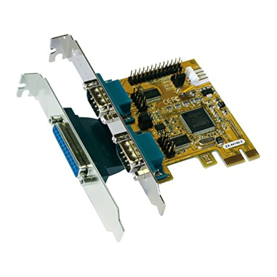
AUFBAU
JP1: Power auf 9 Pin
J6: Parallel Anschluss
Stecker Ein/Aus
S2: 9 Pin Stecker
Seriell Anschluss
S1: 9 Pin Stecker
Seriell Anschluss
BESCHREIBUNG & TECHNISCHE DATEN
Die EX-44140-2 ist eine PCI-Express serielle RS-232 Karte mit 2 seriellen FIFO 16C550
Port und 1 parallel Port für den Anschluss von High-Speed seriellen RS-232 Peripherie
Geräten (z.B. Terminal, Modem, Plotter usw.). Der serielle PCI-Express Bus unterstützt
dabei optimal die Leistung des schnellen 16C550 Chipset mit 256byte FIFO Cache. Die
Karte gewährleistet so eine sichere Datenübertragung und exzellente Performance von
bis zu 115,2KBaud/s! Sie unterstützt alle PCI-Express Slots von x1 bis x16. Es ist nicht
möglich die I/O Adressen und Interrupts manuell einzustellen, da die Einstellungen der
Karte vom System (BIOS) und vom Betriebssystem automatisch vorgenommen werden.
Kompatibilität:
PCI-Express x1 bis x16
Betriebssysteme:
Windows DOS/ 2000/ XP/ Vista/ 7/ 8/ Server 200x/ Mac/ Linux
Anschlüsse:
2x 9 Pin D-Sub Seriell Stecker, 1x 25 Pin D-Sub Parallel Buchse
Lieferumfang:
EX-44140-2, Treiber CD, Anleitung, 25 Pin Parallel Kabel
Zertifikate:
CE
CE CE
CE / FCC / RoHS / WEEE
JUMPER EINSTELLUNG & ANSCHLÜSSE
JP1:
DIS
= Am Pin 9 liegt das Standard Signal RI (Ring Indicator)
PWR
= Am Pin 9 kann jetzt eine Spannung von DC5V oder DC12V
Die Einstellung der Spannung nehmen Sie mit dem JP2 vor. Dies sollte
aber bei Standard Anwendungen nicht verstellt werden.
JP2:
Wenn Sie den Jumper JP1 für auf PWR gesetzt haben, können Sie mit
dem Jumper JP2 den Spannungswert einstellen. Es gibt 3 verschiedene
Spannungsquellen.
AUX5V
(Nur in Verbindung mit JP1 auf PWR!!!)
AUX12V
AUX 5V = 5Volt vom PC-Netzteil
PCI12V
AUX 12V = 12Volt vom PC-Netzteil
PCI 12V = 12Volt vom Mainboard (STANDARD)
J7:
1 +5V
Für AUX Einstellung (JP2) muss J7 mit PC Netzteil verbunden
2 GND
3 GND
werden! Sonst wird die Karte nicht mit Strom versorgt.
4 +12V
JP2: Jumper für die Stromquelle
(Netzteil oder PCI-Express Bus)
J7:
Anschluss für Strom
vom PC Netzteil
J1 & J2: Interner serieller Anschluss
DE97424562 / WHQL
(Werkseinstellung)
eingestellt werden
1

Verwandte Anleitungen für Exsys EX-44140-2


Inhaltszusammenfassung für Exsys EX-44140-2
- Seite 1 If you are ready with the jumper settings, please proceed with the following installation instructions. Because there are large differences between PC’s, we can give you only a Die EX-44140-2 ist eine PCI-Express serielle RS-232 Karte mit 2 seriellen FIFO 16C550 general installation guide. Please refer to your computer’s reference manual whenever in Port und 1 parallel Port für den Anschluss von High-Speed seriellen RS-232 Peripherie...
- Seite 2 Unterschiede zwischen PC‘s gibt, können wir Ihnen nur eine generelle Anleitung zum Einbau geben. Bei Unklarheiten halten Sie sich bitte an die Bedienungsanleitung Ihres The EX-44140-2 is a plug & play high-speed serial RS-232 expansion card for the PCI- Computersystems.