Herunterladen Inhalt Inhalt Diese Seite drucken
ESX Quantum QS-TWO Benutzerhandbuch
Vorschau ausblenden Andere Handbücher für Quantum QS-TWO:

Werbung

Verfügbare Sprachen

Verfügbare Sprachen

BENUTZERHANDBUCH
BENUTZERHANDBUCH
QS-TWO
CLASS D 2-CHANNEL NANO AMPLIFIER
OWNER'S MANUAL
OWNER'S MANUAL
VERS.1.1

Werbung

Inhaltsverzeichnis
loading

Inhaltszusammenfassung für ESX Quantum QS-TWO

  • Seite 1 BENUTZERHANDBUCH BENUTZERHANDBUCH OWNER’S MANUAL OWNER’S MANUAL VERS.1.1 QS-TWO CLASS D 2-CHANNEL NANO AMPLIFIER...
  • Seite 2: Technische Daten

    TECHNISCHE DATEN MODEL QS-TWO KANÄLE SCHALTUNGSPRINZIP CLASS D Digital AUSGANGSLEISTUNG RMS 13,8 V Watt an 4 Ohm 2 x 52 Watt an 2 Ohm 2 x 95 Watt an 4 Ohm mono gebrückt 1 x 190 AUSGANGSLEISTUNG MAX. 13,8 V Watt an 4 Ohm 2 x 10⁴ Watt an 2 Ohm...
  • Seite 3: Sicherheitshinweise

    SICHERHEITSHINWEISE BITTE BEACHTEN SIE DIE FOLGENDEN HINWEISE VOR INBETRIEBNAHME! DAS GERÄT NICHT AN STELLEN EINBAUEN, AN DENEN ES DAS VON IHNEN ERWORBENE GERÄT IST NUR FÜR DEN BETRIEB AN EINEM 12-V-BORDNETZ EINES FAHRZEUGS HOHER FEUCHTIGKEIT ODER STAUB AUSGESETZT IST. Bau- AUSGELEGT.
  • Seite 4: Mechanische Installation

    INSTALLATIONSHINWEISE HINWEIS Um Kurzschlüsse und Stromschläge zu vermeiden, klemmen Sie vor der Installation des Soundsystems unbedingt den Massepol der Fahrzeugbatterie ab. MECHANISCHE INSTALLATION Achten Sie bei der Installation darauf, dass keine serienmäßig im KFZ vorhandenen Teile wie z.B. Kabel, Bordcomputer, Sicherheitsgur- te, Tank oder ähnliche Teile beschädigt bzw.entfernt werden.
  • Seite 5: Elektrische Anschlüsse

    INSTALLATIONSHINWEISE ELEKTRISCHE ANSCHLÜSSE POWER SPEAKER INPUT OUTPUT POWER PROTECT +12V REM BRIDGED IN/OUT FAHRZEUG- BATTERIE < 30 cm > 20 A VOR DEM ANSCHLIESSEN Für den fachgerechten Anschluss des Soundsystems sind geeignete Kabelsets im Fachhandel erhältlich. Achten Sie beim Kauf auf einen ausreichenden Kabelquerschnitt (10 mm ) den passenden Sicherungswert (20 A) sowie auf die Leitfähigkeit der Kabel.
  • Seite 6: Funktionshinweise

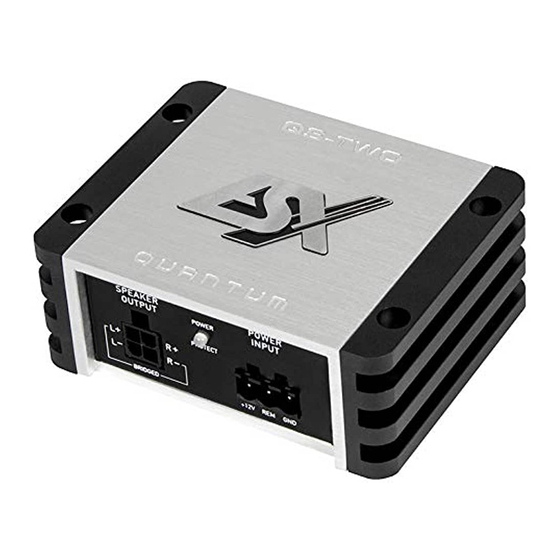
    FUNKTIONSHINWEISE FUNKTIONEN UND BEDIENELEMENTE AUTO LEVEL X-OVER TURN-ON INPUT OFF VOX DC LP HP FULL INPUT OUTPUT Q S–TWO Falls Ihr Steuergerät über keine Einschaltleitung (REM) verfügt, können Sie die automatische Einschaltfunktion des Verstärkers verwenden. Diese funktioniert auf zwei Arten, die am Schalter AUTO TURN-ON eingestellt werden können: VOX: Der Verstärker erkennt beim Einschalten des Steuergeräts über die angeschlossenen Cinchkabel einen Spannungsan- stieg im eintreffenden Audiosignal und schaltet dann den Verstärker ein.
  • Seite 7 SPEAKER OUTPUT + SPEAKER OUTPUT + SPEAKER OUTPUT - SPEAKER OUTPUT - FUNKTIONSHINWEISE INPUT L+ FUNKTIONEN UND BEDIENELEMENTE INPUT L- INPUT R+ INPUT R- OUTPUT L OUTPUT R POWER SPEAKER INPUT OUTPUT POWER PROTECT +12V REM BRIDGED IN/OUT INPUT L INPUT R OUTPUT L Die INPUT Cinch-Eingänge des beiliegenden Kabelsteckers zur Ansteuerung mittels Cinch-Audiokabel mit dem Steuergerät...
  • Seite 8: Anschlussbeispiele

    FUNKTIONSHINWEISE ANSCHLUSSBEISPIELE 2-Kanal-Modus: 1 x Stereo-System (Front oder Rear) Lautsprecher links 2 – 8 Ohm HP od. FULL AUTO POWER SPEAKER LEVEL X-OVER TURN-ON INPUT OUTPUT POWER INPUT PROTECT OFF VOX DC LP HP FULL INPUT OUTPUT Q S–TWO +12V REM BRIDGED IN/OUT Lautsprecher rechts...
  • Seite 9 FUNKTIONSHINWEISE ANSCHLUSSBEISPIELE 1-Kanal-Modus: 1 x Mono Subwoofer gebrückt Subwoofer 4 – 8 Ohm AUTO POWER SPEAKER LEVEL X-OVER TURN-ON INPUT OUTPUT POWER INPUT PROTECT OFF VOX DC LP HP FULL INPUT OUTPUT Q S–TWO +12V REM BRIDGED IN/OUT Stereo Cinch-Audiokabel (L/R oder SUB OUT) vom Steuergerät mit INPUT L / R des Verstärkers verbinden VERKABELUNG...
  • Seite 10: Fehlerbehebung

    FEHLERBEHEBUNG STÖRUNGEN / INTERFERENZEN Die Ursache von Interferenzen sind häufig die verlegten Kabel. Besonders anfällig dafür sind die Strom- und Cinchkabel des Sound Sys- tems. Oftmals werden Interferenzen durch Generatoren (Lichtmaschine) oder andere elektronische Steuergeräte des KFZ (Benzinpum- pe, Klimaanlage etc.) verursacht. Die meisten dieser Probleme können durch korrektes und sorgfältiges Verkabeln vermieden werden. Hier finden Sie dazu einige Hilfestellungen: 1.
  • Seite 11 FEHLERBEHEBUNG Fehler: keine Funktion Ursache: Lösung: 1. Die Stromversorgungskabel sind nicht korrekt angeschlossen. Erneute Überprüfung 2. Die Kabel haben keinen elektrischen und mechanischen Kontakt. Erneute Überprüfung 3. Die Remote-Steuerleitung des Steuergeräts (Autoradio) ist nicht korrekt am Verstärker angeschlossen. Erneute Überprüfung 4.
  • Seite 12: Specifications

    SPECIFICATIONS MODEL QS-TWO CHANNELS CIRCUIT CLASS D Digital OUTPUT POWER RMS 13,8 V Watts @ 4 Ohms 2 x 52 Watts @ 2 Ohms 2 x 95 Watts @ 4 Ohms mono bridged 1 x 190 OUTPUT POWER MAX. 13,8 V Watts @ 4 Ohms 2 x 10⁴ Watts @ 2 Ohms...
  • Seite 13: Safety Instructions

    SAFETY INSTRUCTIONS PLEASE NOTE THE FOLLOWING ADVICE BEFORE THE FIRST OPERATION! DO NOT INSTALL THE DEVICE AT LOCATIONS, WHERE IT THE PURCHASED DEVICE IS ONLY SUITABLE FOR AN OP- WILL BE EXPOSED TO HIGH HUMIDITY AND DUST. Install the ERATION WITH A 12V ON-BOARD ELECTRICAL SYSTEM OF A VEHICLE.
  • Seite 14: Installation Instructions

    INSTALLATION INSTRUCTIONS NOTE Before you start with the installation of the sound system, disconnect necessarily the GROUND connection wire from the battery to avoid any risk of electric shocks and short circuits. MECHANICAL INSTALLATION Avoid any damages on the components of the vehicle like air bags, cables, board computer, seat belts, gas tank or the like. Ensure that the chosen location provides a sufficient air circulation for the amplifier.
  • Seite 15: Electrical Interconnection

    INSTALLATION INSTRUCTIONS ELECTRICAL INTERCONNECTION POWER SPEAKER INPUT OUTPUT POWER PROTECT +12V REM BRIDGED IN/OUT VEHICLE‘S BATTERY < 30 cm > 20 A BEFORE CONNECTING For the professional installation of a sound system, car audio retail stores offers appropriate wire kits. Ensure a sufficient profile section (10 mm ) , the suitable fuse rating (20 A) and the conductivity of the cables when you purchase your wiring kit.
  • Seite 16: Functional Instructions

    FUNCTIONAL INSTRUCTIONS OPERATING ELEMENTS AUTO LEVEL X-OVER TURN-ON INPUT OFF VOX DC LP HP FULL INPUT OUTPUT Q S–TWO If your head unit does not have a turn-on signal (REM), you can use the automatic turn-on function of the amplifier. This works in two ways, which can be set at the AUTO TURN-ON switch: VOX: The amplifier then detects a voltage increase in the incoming audio signal when switching on the head unit via the attached RCA cable and then switches on the amplifier.
  • Seite 17 SPEAKER OUTPUT - SPEAKER OUTPUT - FUNCTIONAL INSTRUCTIONS INPUT L+ INPUT L- OPERATING ELEMENTS INPUT R+ INPUT R- OUTPUT L OUTPUT R POWER SPEAKER INPUT OUTPUT POWER PROTECT +12V REM BRIDGED IN/OUT INPUT L INPUT R OUTPUT L Connect the INPUT RCA jacks of the included wire harness with the head unit by using appropriate audio signal cables. OUTPUT R INPUT L INPUT R...
  • Seite 18: Interconnection Example

    FUNCTIONAL INSTRUCTIONS INTERCONNECTION EXAMPLE 2-channel-mode: 1 x Stereo-System (Front or Rear) Loudspeaker left 2 – 8 Ohms HP or. FULL AUTO POWER SPEAKER LEVEL X-OVER TURN-ON INPUT OUTPUT POWER INPUT PROTECT OFF VOX DC LP HP FULL INPUT OUTPUT Q S–TWO +12V REM BRIDGED IN/OUT...
  • Seite 19 FUNCTIONAL INSTRUCTIONS INTERCONNECTION EXAMPLE 1-channel-mode: 1 x Mono Subwoofer bridged Subwoofer 4 – 8 Ohms AUTO POWER SPEAKER LEVEL X-OVER TURN-ON INPUT OUTPUT POWER INPUT PROTECT OFF VOX DC LP HP FULL INPUT OUTPUT Q S–TWO +12V REM BRIDGED IN/OUT Connect stereo RCA output (L/R or SUB OUT) of the head unit with INPUT (L/R) of the amplifier INTERCONNECTION...
  • Seite 20: Troubleshooting

    TROUBLE SHOOTING ELECTRICAL INTERFERENCES The reason for interferences are often the routed cables and wires. Especially the power and audio cables (RCA) of your sound system are vulnerable. Often these interferences are caused by electric generators or other electrical units (fuel pump, AC etc.) of the car. The most of these problems can be prevented by a correct and careful wiring.
  • Seite 21 TROUBLE SHOOTING Malfunction: no function Reason: Remedy: 1. The power supply connection of the device is not correct Recheck 2. The cables have no mechanical or electrical contact Recheck 3. The remote turn-on connection from the head unit to the amplifier is not correct Recheck 4.
  • Seite 22 NOTES...
  • Seite 23 NOTES...
  • Seite 24 Audio Design GmbH Am Breilingsweg 3 · D-76709 Kronau/Germany Tel. +49 7253 - 9465-0 · Fax +49 7253 - 946510 www.esxaudio.de · www.audiodesign.de © Audio Design GmbH, all rights reserved. Technical changes, errors and mistakes reserved.

Inhaltsverzeichnis