ESX QUANTUM QE80.8DSP Benutzerhandbuch

Verwandte Anleitungen für ESX QUANTUM QE80.8DSP


Inhaltszusammenfassung für ESX QUANTUM QE80.8DSP
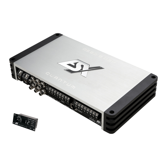
- Seite 1 BENUTZERHANDBUCH BENUTZERHANDBUCH OWNER’S MANUAL OWNER’S MANUAL VERS.1.3 QE80.8DSP CLASS D 8-CHANNEL AMPLIFIER WITH DSP PROCESSOR...
-
Seite 2: Inhaltsverzeichnis
INHALTSVERZEICHNIS SICHERHEITSHINWEISE INSTALLATIONSHINWEISE Mechanische Installation ........................4 Elektrische Anschlüsse ........................5 FUNKTIONSHINWEISE Funktionen und Bedienelemente .......................6 Installation der DSP-Software ......................8 Konfiguration des DSP-Verstärkers per Software ................8 Bedienoberfläche der Software .......................10 Anschlussbeispiel ..........................12 Übersicht der möglichen Anschlussbeispiele ..................15 Praxistipp: Laufzeitkorrektur ......................16 ALLGEMEINE HINWEISE Technische Daten ..........................17 Garantiehinweis ..........................17 FEHLERBEHEBUNG... -
Seite 3: Sicherheitshinweise
SICHERHEITSHINWEISE BITTE BEACHTEN SIE DIE FOLGENDEN HINWEISE VOR INBETRIEBNAHME! DAS VON IHNEN ERWORBENE GERÄT IST NUR FÜR DEN BETRIEB DAS GERÄT NICHT AN STELLEN EINBAUEN, AN DENEN ES HOHER AN EINEM 12-V-BORDNETZ EINES FAHRZEUGS AUSGELEGT. An- FEUCHTIGKEIT ODER STAUB AUSGESETZT IST. Bauen Sie das Ge- dernfalls besteht Feuergefahr, die Gefahr eines elektrischen Schlages oder rät so ein, dass es vor hoher Feuchtigkeit und Staub geschützt ist. -
Seite 4: Installationshinweise
INSTALLATIONSHINWEISE HINWEIS Bevor Sie mit der Installation des Soundsystems beginnen, trennen Sie unbedingt den Massepol der Fahrzeugbatterie ab, um Kurzschlüsse und Stromschläge zu vermeiden. MECHANISCHE INSTALLATION Achten Sie bei der Installation darauf, dass keine serienmäßig im KFZ vorhandenen Teile wie z.B. Kabel, Bordcomputer, Sicherheitsgur- te, Tank oder ähnliche Teile beschädigt bzw.entfernt werden. -
Seite 5: Elektrische Anschlüsse
– – – SUB L PRT. POW. – – POW. QE80.6 DSP INSTALLATIONSHINWEISE LINE OUTPUT QE80.4 DSP PC CONNECT AUX IN OFF ON +12V AUTO TURN ON PC CONNE AUX IN ONLY WITH HIGH LEVEL INPUT OPTICAL INPUT +12V HIGH LEVEL INPUT WiFi BOX REMOTE SUB R... -
Seite 6: Funktionshinweise
FUNKTIONSHINWEISE LINE INPUT LINE OUTPUT NPUT BRIDGED BRIDGED BRIDGED – – – – – – PRT. POW. QE80.6 DSP FUNKTIONEN UND BEDIENELEMENTE DES VERSTÄRKERS AUX IN PC CONNECT OFF ON +12V AUTO TURN ON ONLY WITH HIGH LEVEL INPUT OPTICAL INPUT HIGH LEVEL INPUT WiFi BOX REMOTE... -
Seite 7: Funktionen Und Bedienelemente Der Fernbedienung
FUNKTIONSHINWEISE BELEGUNG KABELSATZ HOCHPEGEL-AUDIOEINGÄNGE BRAUN/SCHWARZ SUB R – 9 11 BRAUN SUB R + ORANGE/SCHWARZ SUB L – 8 10 12 ORANGE SUB L + LILA/SCHWARZ REAR R – LILA REAR R + GRÜN REAR L + GRÜN/SCHWARZ REAR L – GRAU FRONT R + 10) GRAU/SCHWARZ... -
Seite 8: Installation Der Dsp-Software
FUNKTIONSHINWEISE INSTALLATION DER DSP-SOFTWARE Die DSP Software X-CONTROL ist für alle Computer mit einem Windows™ Betriebssystem ab XP und einem USB-Anschluss geeignet. Die Installation benötigt ca. 25 MB freien Speicherplatz. Prinzipbedingt sollte dafür ein tragbarer Laptop-Computer verwendet werden. Legen Sie zunächst die beiliegende Software CD-ROM in das Computerlaufwerk ein oder laden Sie die DSP-Software X-CONTROL über den Internetlink http://www.audiodesign.de/dsp herunter. - Seite 9 FUNKTIONSHINWEISE Wurde der Test erfolgreich durchgeführt erscheinen 4 Häkchen in den Checkboxen. Drücken Sie dann auf [OK] Click here to start um fortzufahren. Sollte eines der Häkchen bei einer Checkbox nicht erscheinen, liegt ein Problem vor welches zu einer Fehlfunktion führen kann. Beachten Sie dazu die Angaben im Kapitel Fehlerbehe- bung.
-
Seite 10: Bedienoberfläche Der Software
FUNKTIONSHINWEISE BEDIENOBERFLÄCHE DER SOFTWARE Hier können Sie unzählige Einstellungen vornehmen und an Ihr Soundsystem anpassen, welche in Echtzeit über den DSP-Prozessor so- fort hörbar sind. Sobald Sie mit der Konfiguration eines Settings fertig sind, kann dieses auf den einen Speicherplatz im DSP-Prozessor übertragen werden. - Seite 11 FUNKTIONSHINWEISE 2. SOURCE: • Hier wählen Sie zwischen den einzelnen Eingangsquellen OPTICAL (Optischer Eingang), MAIN (RCA/Cinch Audioeingänge) bzw. HI LEVEL (Hochpegel-Audioeingänge), AUX (3,5 mm Klinke Stereoeingang). Der WiFi-Box-Anschluss wird derzeit nicht unterstützt. 3. CH-SETTING: • Hier wählen Sie den jeweiligen Ausgangskanal bzw. das Ausgangskanalpaar aus, bei welchem Sie die Einstellungen verändern möchten.
-
Seite 12: Anschlussbeispiel
FUNKTIONSHINWEISE POWER INPUT LINE INPUT BRIDGED BRIDGED G F E – – – – SUB L ANSCHLUSSBEISPIEL PRT. – – POW. LINE OUTPUT QE80.4 DSP 8-Kanal-Modus: 3-Wege-Aktiv-System + 1 x Subwoofer AUX IN PC CONNECT OFF ON +12V AUTO TURN ON SUB R OPTICAL INPUT ONLY WITH HIGH LEVEL INPUT... - Seite 13 FUNKTIONSHINWEISE KONFIGURATION DER KANÄLE A/B (HOCHTÖNER) 1. Wählen Sie unter SOURCE die Einstellung MAIN. 2. Wählen Sie das Kanalpaar A & B unter CH SETTING aus indem Sie auf das Schlosssymbol klicken. 3. Wählen Sie unter CROSSOVER > FILTER TYPE die Einstellung HP (Hochpassfilter) 4.
- Seite 14 FUNKTIONSHINWEISE ANPASSUNG DER LAUTSTÄRKEPEGEL Passen Sie die Pegel der einzelnen Kanäle nach Ihren Wünschen passend zu den Audiokomponenten und Gegebenheiten im Fahr- zeuginneren an. Beachten Sie hierzu folgende Hinweise: • Senken Sie die Ausgangslautstärke unter MAIN auf -10dB ab um Verzerrungen zu vermeiden. •...
-
Seite 15: Übersicht Der Möglichen Anschlussbeispiele
FUNKTIONSHINWEISE ÜBERSICHT DER MÖGLICHEN ANSCHLUSSBEISPIELE Neben dem auf den vorangegangenen Seiten ausführlich beschriebenen Anschlussbeispiel bietet der DSP-Verstärker viele weitere Systemkonfigurationen. Die beiden häufigsten sind hier in Kurzform beschrieben: Kanäle Beispiel 1 Beispiel 2 Front mit Vollbereichslautsprechern Front 2-Wege Aktiv-System Rear mit Kickbässen und Vollbereichslautsprechern Rear mit Vollbereichslautsprechern Subwoofer Subwoofer... -
Seite 16: Praxistipp: Laufzeitkorrektur
PRAXISTIPP: LAUFZEITKORREKTUR Wie stelle ich in der DSP-Software den richtigen Abstand der Laufzeitkorrektur ein, um alle Lautsprecher des Soundsystems aufeinander einzustellen und der Schall gleichzeitig beim Hörer ankommt? Messen Sie zuerst den Abstand der Lautsprecher zur akustischen Bühnenmitte. In diesem Fall ist diese der Fahrersitz auf Höhe der Ohren. -
Seite 17: Allgemeine Hinweise
Alle ESX Verstärker sind mit einer individuelle Seriennummer versehen, die für statistische und servicebedingte Zwecke aufgezeichnet wird. Alle ESX Verstärker sind zudem mit einer CE-Kennzeichnung versehen. Damit sind die Geräte für den Betrieb in Fahrzeugen inner- halb der Europäischen Union (EU) zertifiziert. -
Seite 18: Fehlerbehebung
FEHLERBEHEBUNG Fehler: keine Funktion Ursache: Lösung: 1. Die Stromversorgungskabel sind nicht korrekt angeschlossen. Erneute Überprüfung 2. Die Kabel haben keinen elektrischen und mechanischen Kontakt. Erneute Überprüfung 3. Die Remote-Steuerleitung des Steuergeräts (Autoradio) ist nicht korrekt am Verstärker angeschlossen. Erneute Überprüfung 4. - Seite 19 FEHLERBEHEBUNG Fehler: kein Ton vom Subwoofer Ursache: Lösung: 1. Die Lautstärke des Subwoofer-Ausgangs (Kanal G/H bzw. SUB OUT) ist an der Fernbedienung zu leise eingestellt. Regler der Fernbedienung drücken und halten, Lautstärke erhöhen wie auf Seite. 7 beschrieben. Fehler: „ERROR“-Meldung bei Verbindung zwischen DSP-Gerät und Computer Ursache: Lösung: 1.
- Seite 20 FEHLERBEHEBUNG STÖRUNGEN / INTERFERENZEN Die Ursache von Interferenzen sind meist immer die verlegten Kabel. Besonders anfällig dafür sind die Strom- und Cinchkabel des Sound Systems. Oftmals werden Interferenzen durch Generatoren (Lichtmaschine) oder andere elektronische Steuergeräte des KFZ (Benzinpumpe, Klimaanlage etc.) verursacht. Die meisten dieser Probleme können durch korrektes und sorgfältiges Verkabeln vermie- den werden.
- Seite 21 NOTITZEN...
- Seite 41 NOTES...
- Seite 42 NOTES...
- Seite 43 NOTES...