Camille Bauer SINEAX A210 Betriebsanleitung
Vorschau ausblenden
Andere Handbücher für SINEAX A210:
- Bedienungsanleitung (9 Seiten) ,
- Betriebsanleitung (32 Seiten)
Inhaltsverzeichnis
Werbung
Verfügbare Sprachen
Verfügbare Sprachen
Betriebsanleitung
Multifunktionales
Leistungsmessgerät
Mode d'emploi
Indicateur puissance
multifunction
Operating Instructions
Multifunctional
Power Monitor
SINEAX A 210/A 220
Geräte dürfen nur
fachgerecht entsorgt
werden!
Sicherheitshinweise
Die Installation und Inbetriebnahme darf nur
durch geschultes Personal erfolgen.
Überprüfen Sie vor der Inbetriebnahme,
dass:
- die maximalen Werte aller Anschlüsse
nicht überschritten werden, siehe Kapitel
«Technische Daten»
- die Anschlussleitungen nicht beschädigt
und bei der Verdrahtung spannungsfrei
sind
- Energierichtung und Phasenfolge stim-
men.
Das Gerät muss ausser Betrieb gesetzt
werden, wenn ein gefahrloser Betrieb (z.B.
sichtbare Beschädigungen) nicht mehr
möglich ist. Dabei sind alle Anschlüsse
abzuschalten. Das Gerät ist an unser Werk
bzw. an eine durch uns autorisierte Service-
stelle zu schicken.
Ein Öffnen des Gehäuses bzw. ein Eingriff in
das Gerät ist verboten. Das Gerät hat keinen
eigenen Netzschalter. Achten Sie darauf,
dass beim Einbau ein gekennzeichneter
Schalter in der Installation vorhanden ist
und dieser vom Benutzer leicht erreicht
werden kann.
Bei einem Eingriff in das Gerät erlischt der
Garantieanspruch.
Inhaltsverzeichnis
Kurzanleitung zum Ändern
der Parameter
Diagramm Programmierung
Masszeichnungen
Camille Bauer AG
Aargauerstrasse 7
CH-5610 Wohlen/Switzerland
Telefon +41 56 618 21 11
Telefax +41 56 618 35 35
info@camillebauer.com
www.camillebauer.com
Les appareils ne peu-
vent être éliminés que
de façon appropriée!
Consignes de sécurité
L'installation et la mise en service doivent
impérativement être faites par du personnel
spécialement formé.
Avant la mise en service vérifi er les points
suivants:
- ne pas dépasser les valeurs maximales
de tous les raccordements, voir chapitre
«Caractéristiques techniques».
- s'assurer que les lignes raccordées ne
soient ni abimées ni sous tension.
- vérifi er que le sens d'énergie et la suite des
phases soient corrects.
L'appareil doit être mis hors service si un
fonctionnement sans danger n'est plus pos-
sible (p. ex. suite à un dommage visible). Tous
les raccordements doivent être déconnectés.
L'appareil doit être retourné en usine resp.
à un atelier autorisé pour faire des travaux
de service.
Toute intervention et l'ouverture de l'appareil
sont interdites. L'appareil ne possède pas
d'interrupteur principal propre. Faire attention
qu'un interrupteur bien repéré et facilement
atteignable par l'utilisateur soit installé.
Toute intervention dans l'appareil entraîne
l'extinction de la clause de garantie.
Sommaire
Seite
2
2
2
3
3
3
5
5
6
6
7
7
7
Instruction abrégée pour modifi er
29
les paramètres
30
Diagramme des programmations
32
Croquis d'encombrements
A 210/A 220 Bd-f-e
The instruments must
only be disposed of in
the correct way!
Safety notes
The installation and commissioning should
only be carried out by trained personnel.
Check the following points before com-
missioning:
- that the maximum values for all the
connections are not exceeded, see the
"Technical data" section,
- that the connection wires are not dam-
aged, and that they are not live during
wiring,
- that the power fl ow direction, and the
phase rotation are correct.
The instrument must be taken out of service
if safe operation is no longer possible (e.g.
visible damage). In this case, all the con-
nections must be switched off. The instru-
ment must be returned to the factory or to
an authorized service dealer.
It is forbidden to open the housing and to
make modifi cations to the instrument. The
instrument is not equipped with an integrat-
ed circuit breaker. During installation check
that a labeled switch is installed and that it
can easily be reached by the operators.
Unauthorized repair or alteration of the unit
invalidates the warranty.
Contents
Page
11
11
11
12
12
12
14
14
15
15
16
16
16
29
30
Programming charts
32
Dimensional drawings
151 118-06
06.10
Page
20
20
20
21
21
21
23
23
24
24
25
25
25
29
30
32
1
Werbung
Inhaltsverzeichnis

Verwandte Anleitungen für Camille Bauer SINEAX A210


Inhaltszusammenfassung für Camille Bauer SINEAX A210
-
Seite 1: Inhaltsverzeichnis
Betriebsanleitung Multifunktionales Leistungsmessgerät Mode d’emploi Indicateur puissance multifunction Camille Bauer AG Operating Instructions Aargauerstrasse 7 Multifunctional CH-5610 Wohlen/Switzerland Telefon +41 56 618 21 11 Power Monitor Telefax +41 56 618 35 35 info@camillebauer.com SINEAX A 210/A 220 www.camillebauer.com A 210/A 220 Bd-f-e 151 118-06 06.10... -
Seite 2: Kurzbeschreibung
Kurzbeschreibung Hilfsenergie* DC-, AC-Netzteil 50 bis 400 Hz Das Gerät A 210 ist ein Einbaugerät im Format 96 x 96 mm, das 100 bis 230 V AC/DC ±15% oder 24 bis 60 V AC/DC ±15% Gerät A 220 ist ebenfalls ein Einbaugerät im Format 144 x 144 mm. Leistungsaufnahme: <... -
Seite 3: Inbetriebnahme
Spannungsanschluss nach folgender Tabelle vornehmen: Messeingang, je nach Messaufgabe Strom- Klemmen wandler No. 1 Dreileiter- 3~500/290V 5A 50/60Hz CAT III Mat: 123456/1234567/123 Camille Bauer AG Drehstromnetz SINEAX A210 Man: 10/02 Switzerland ungleich- 100-230V AC/DC 50-400Hz 3VA belastet LOCK 22 21... - Seite 4 Netzformen/ Klemmenbelegung Anwendung Vierleiter- Drehstromnetz gleichbelastet I: L1 Bei Strommessung über L2 bzw. L3, Spannungsanschluss nach folgender Tabelle vornehmen: Stromwandler Klemmen Vierleiter- Drehstromnetz ungleich- belastet 3 einpolig isolierte Spannungswandler im Hochspannungsnetz...
-
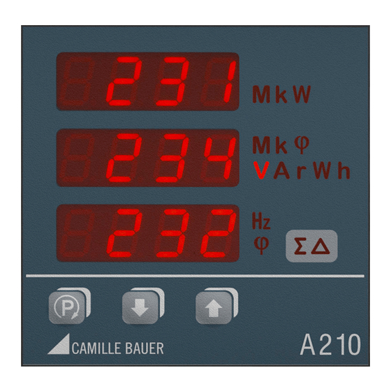
Seite 5: Anzeige Und Bedienung
Anzeige und Bedienung Einheitenanzeige (abgebildet ist der oben SINEAX A 210. Die Anzeige und die 7-Segment- mitte anzeigen Bedienung sind jedoch beim SINEAX A 220 unten Systemanzeige identisch.) Powerfaktor Taste für Up-Taste cos 4-Quadranten- Programmierung darstellung und Anzeige Down-Taste Beispiel Beispiel Beispiel Einheiten-... -
Seite 6: Anzeigeebenen
Anzeigeebenen Einphasig, Dreileiter gleichbelastet, Vierleiter gleichbelastet Innerhalb einer Ebene (1, 2, 3 …) können Sie mit der Taste die 3 Anzeigen in den nächsten Modus (a, b, c, …) umschalten. Am Ende des Modus beginnt die Anzeige wieder mit dem Modus a. In die nächste Ebene wechseln Sie durch kurzes Drücken der Tasten. -
Seite 7: Sperren Der Programmierung
Programmierung Hinweise: Die Anschlussart und die Wandlerfaktoren müssen immer zuerst Alle Parameter lassen sich jederzeit anzeigen. Für Veränderungen eingestellt werden, weil die Messwertanzeigen, Grenzwerteinstel- muss aber der Jumper auf der Rückseite des Gerätes gezogen sein lungen etc. davon abhängig sind. (Stellung nicht auf LOCK). - Seite 8 Anzeige oben Anzeige unten Bedeutung Hinweis Anzeige mitte (Auswahl, * = Default) Betriebsart der beiden Digitalausgänge (Mode) «out.1» und «out.2» Ausgang ausgeschaltet Ansteuerung via Bus-Schnittstelle bleibt jedoch möglich Energie-Impuls-Ausgang Der Ausgang erzeugt Energie-Impulse mit der unter eingestellten Impulsrate. Die auszugebende Zählergrösse kann unter ausgewählt werden.
- Seite 9 Anzeige oben Anzeige unten Bedeutung Hinweis Anzeige mitte (Auswahl, * = Default) Quelle des Energiezählers für Impulsausgang Blindenergie kapazitiv Niedertarif Blindenergie kapazitiv Hochtarif Blindenergie induktiv Niedertarif Blindenergie induktiv Hochtarif Wirkenergie Abgabe Niedertarif (outgoing low tariff) Wirkenergie Abgabe Hochtarif (outgoing high tariff) Wirkenergie Bezug Niedertarif (incoming low tariff) Wirkenergie Bezug Hochtarif...
- Seite 10 -Taste drücken (aktuelle Einstellung -Taste 3x drücken Primärspannung) -Taste drücken (aktuelle Einstellung in Minuten) -Taste drücken (linke Ziffer blinkt) -Taste drücken (linke Ziffer blinkt) bzw. -Taste drücken bis gewünschte Ziffer erscheint -Taste drücken (mittlere Ziffer blinkt) bzw. -Taste drücken bis gewünschte Ziffer erscheint bzw.
-
Seite 11: Description Brève
Description brève Energie auxiliaire* Les appareils A210/A220 sont des instruments pour montage encas- Bloc d’alimentation CC, CA 50 à 400 Hz tré du format 96 x 96 mm (A 210) ou 144 x 144 mm (A 220) et sert 100 à 230 V CA/CC ±15% ou 24 à 60 V CA/CC ±15% à... -
Seite 12: Mise En Service
Entrée de mesure, suivant type désiré de mesure courant No. 1 Courant triphasé 3 fils 3~500/290V 5A 50/60Hz CAT III à charges Mat: 123456/1234567/123 Camille Bauer AG SINEAX A210 Man: 10/02 Switzerland dés- 100-230V AC/DC 50-400Hz 3VA équilibrées LOCK... - Seite 13 Réseau/ Disposition des bornes Application Courant triphasé 4 fils à charges équilibrées I: L1 Pour la mesure du courant en L2 resp. L3, connecter les tensions selon tableau ci-après: Transforma- Bornes teur de courant Courant triphasé 4 fils à charges dés- équilibrées 3 transformateurs de tensions unipolaires...
-
Seite 14: Affi Chage Et Utilisation
Affi chage et utilisation affichage des unités L’affi chage et utilisation en haut pour SINEAX A 210 et A 220 sont identiques. affichage à 7 segments milieu en bas affichage du système Facteur de touche Up touche pour la puissance cos (vers le haut) programmation mode 4 quadrants... -
Seite 15: Niveaux D'affi Chage
Monophasé, 3 fi ls à charges équilibrées, 4 fi ls à charges Niveaux d’affi chage équilibrées En dedans d’un niveau (1, 2, 3, …), vous pouvez commuter les 3 affi chages au mode suivant (a, b, c, …) en appuyant sur la touche . -
Seite 16: Programmation
Programmation Informations importantes: Le genre de raccordement et les rapports des transformateurs de Tous les paramètres peuvent à chaque instant être affi chés. Pour mesure doivent toujours être introduites en premier, étant donnée des modifi cations, il faut toutefois retirer le pontet placé au dos de que les affi... - Seite 17 Affichage en haut Affichage en bas Signification Information Affichage au centre (Sélection, * = défaut) Mode de fonctionnement des deux (mode) sorties numériques «out.1» et «out.2» Sortie déclenchée La sélection de l’interface bus est toutefois possible Sortie d’impulsions énergie La sortie produit des impulsions d’énergie à la cadence ajustée sous La valeur du chiffre de sortie est sélectionnée sous...
- Seite 18 Affichage en haut Affichage en bas Signification Information Affichage au centre (Sélection, * = défaut) Source du compteur d’énergie à impulsions Energie réactive capacitive tarif réduit Energie réactive capacitive tarif normal Energie réactive inductive tarif réduit Energie réactive inductive tarif normal Energie active fournie tarif réduit (outgoing low tariff) Energie active fournie tarif normal...
- Seite 19 Appuyer la touche (ajustage actuel de la Appuyer 3 fois la touche tension primaire) Appuyer la touche (affi chage actuel en Appuyer la touche (le chiffre à gauche clignote) minutes) Appuyer la touche (le chiffre à gauche clignote) Appuyer les touches jusqu’à...
-
Seite 20: Brief Description
Brief description Power supply* The A 210/A 220 are panel mounting instruments for monitoring AC DC, AC power pack 50 to 400 Hz systems with dimensions 96 x 96 mm (A 210) and 144 x 144 mm 100 to 230 V AC/DC ±15% or 24 to 60 V AC/DC ±15% (A 220). -
Seite 21: Commissioning
Terminals transf. Measuring input, acc. to measuring mode No. 1 3 wire 3 phase asymmetric 3~500/290V 5A 50/60Hz CAT III Mat: 123456/1234567/123 Camille Bauer AG load SINEAX A230 Man: 10/02 Switzerland 100-230V AC/DC 50-400Hz 3VA LOCK 22 21 14 15... - Seite 22 System/ Terminals application 4 wire 3 phase symmetric load I: L1 Connect the voltage according to the following table for current measurement in L2 or L3: Current trans. Terminals 4 wire 3 phase asymmetric load 3 single-pole insulated voltage transformers in high-voltage system...
-
Seite 23: Display And Operating
Display and operating Units display Display and operating are identical for the SINEAX A 210 and 7-segment centre A 220 display bottom System display Power factor Up key Key for cos 4 quadrant programming operation and display Down key Example Example Example Units... -
Seite 24: Display Levels
Display levels Single-phase, 3 wire symmetric load, 4 wire symmetric load Within a level (1, 2, 3 …) you can change the 3 displays to the next mode (a, b, c, ...) with the key. From the last mode, the display changes to mode a again. -
Seite 25: Programming
Programming Hints: First you have to set the system confi guration and the transformer All parameters may be displayed at any time. For modifi cations ratios because further measurand selections, alarm limit settings the jumper on the backside of the device must be removed (not on etc. - Seite 26 Topmost display Undermost display Meaning Hints Middle display (Selection, * = default) Operating mode of both digital outputs (mode) “out.1” and “out.2” Output switched-off Simulation via interface module is still possible Energy pulse output The output generates energy pulses depending on the rate set under The meter measurands to output may be selected under Alarm output...
- Seite 27 Topmost display Undermost display Meaning Hints Middle display (Selection, * = default) Source of energy meters for pulse output Reactive energy capacitive, low tariff Reactive energy capacitive, high tariff Reactive energy inductive, low tariff Reactive energy inductive, high tariff Active energy outgoing, low tariff (outgoing low tariff) Active energy outgoing, high tariff (outgoing high tariff)
- Seite 28 Press (present setting of primary voltage) Press three times Press (leftmost digit fl ashes) Press (present setting of synchronization interval in minutes) Press until desired number appears Press (left digit fl ashes) Press middle digit fl ashes) Press until desired number appears Press (rightmost digit fl...
-
Seite 29: Brief Operating Instruction For Parameter Modifi Cation
Konformitätserklärung / Certifi cat de conformité / Declaration of conformity SINEAX A 220 SINEAX A 210 EG - KONFORMITÄTSERKLÄRUNG EG - KONFORMITÄTSERKLÄRUNG EC DECLARATION OF CONFORMITY EC DECLARATION OF CONFORMITY D o k u m e n t - N r . / A 2 1 0 _ C E - k o n f . - Seite 30 Anzeige-Ebene Niveaux d’affichage Display level Anschlussart Ausgang 1 Wandlerfaktoren Menü- Possibilité de Sortie 1 Rapport des trans- Ebene raccordement formateurs de mesure Output 1 Niveaux System configuration Transformer ratios du menu Menu level Parameter- Ebene Niveaux du paramètre Parameter level Kurzanleitung zum Ändern der Parameter siehe vorherige Seite!
- Seite 31 Messwert-Anzeige Affichage des valeurs de mesure Measurands display Zurück aus jeder Anzeige Retour de chaque affichage > 2s > 2s Back from any other display Ausgang 2 Leistungs-Intervall Sortie 2 Intervalle de puissance Output 2 Power interval Parameter des jeweiligen Erweiterungsmoduls Paramètres du module d’extension respectif...
- Seite 32 Masszeichnung / Croquis d’encombrement / Dimensional drawing SINEAX A 210 Schalttafelausschnitt 2 – 25,4 Découpe dans le tableau de commande Panel cutout +0.8 min. 12 ≤ 65* * mit Erweiterungsmodul Massangaben in mm * avec module d’extension * with extension module Toutes les dimensions sont indiquées en mm All dimensions in mm...