Inhaltsverzeichnis
Werbung
Verfügbare Sprachen
Verfügbare Sprachen
Quicklinks
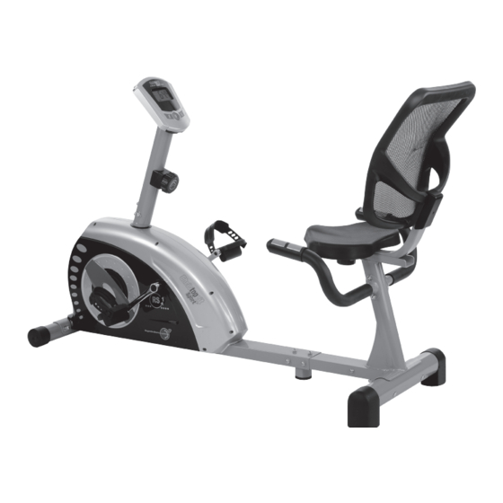
Heimsport-Trainingsgerät
Sitzheimtrainer
RS 1
D
GB
Montage- und Bedienungsanleitung
Assembly and exercise instructions
für Bestell-Nr. 1212
for Order No. 1212
F
NL
Notice de montage et d'utilisation du
Montage- en bedieningshandleiding voor
No. de commande 1212
Bestellnummer 1212
RU
Инструкция по монтажу и эксплуатации
№ заказа 1212
1
Werbung
Kapitel
Inhaltsverzeichnis

Verwandte Anleitungen für Christopeit Sport RS 1


Inhaltszusammenfassung für Christopeit Sport RS 1
- Seite 1 Heimsport-Trainingsgerät Sitzheimtrainer RS 1 Montage- und Bedienungsanleitung Assembly and exercise instructions für Bestell-Nr. 1212 for Order No. 1212 Notice de montage et d’utilisation du Montage- en bedieningshandleiding voor No. de commande 1212 Bestellnummer 1212 Инструкция по монтажу и эксплуатации № заказа 1212...
-
Seite 2: Inhaltsverzeichnis
Inhaltsübersicht Contents Page 1. Wichtige Empfehlungen und Sicherheitshinweise Seite 2 2. Einzelteileübersicht Seite 3 - 4 3. Stückliste Seite 5 - 6 4. Montageanleitung mit Explosionsdarstellungen Seite 7 - 10 Sommaire Page 5. Computeranleitung Seite 11 6. Trainingsanleitung Seite 12 Inhoudsopgave Pagina 31 Sehr geehrte Kundin, sehr geehrter Kunde Wir gratulieren Ihnen zum Kauf dieses Heimsport-Trainingsgerätes und wünschen Ihnen viel Vergnügen damit. -
Seite 5: Stückliste
Stückliste - Ersatzteilliste Wenn ein Bauteil nicht in Ordnung ist oder fehlt, oder wenn Sie in Zukunft ein Ersatzteil benötigen, wenden Sie sich bitte an uns. RS 1 Best.-Nr. 1212 Technische Daten: Stand: 01. 05. 2012 Adresse: Top-Sports Gilles GmbH Friedrichstr. - Seite 6 Abbildungs- Bezeichnung Abmessung Menge Montiert an ET-Nummer Stück Abbildungs Nr. Unterlegscheibe 6//12 39-10013-VC Schraube M6x40 23+25 39-9979 Schraube 4,2x18 48+57+58 39-9909-SW Abdeckung 36-1213-14-BT Gummiring 1+48 36-9211-31-BT Schraube M5x12 39-10188 Federring für M8 4+20+45 39-9864-VC Seilzug 36-1212-06-BT Computer 36-1208-03-BT Schloßschraube M8x75 39-10019-CR Mutter 39-10032...
-
Seite 7: Montageanleitung Mit Explosionsdarstellungen
Montageanleitung Entnehmen Sie alle Einzelteile der Verpackung, legen diese auf den Boden und kontrollieren die Vollzähligkeit grob anhand der Monta- geschritte. Zu beachten ist dabei, dass einige Teile direkt mit dem Grundgestell verbunden sind und vormontiert wurden. Des Weiteren sind auch einige andere Einzelteile schon zu Einheiten zusammengefügt worden. - Seite 8 Schritt 3: Montage des Sitzaufnahme (23) am Sitzrahmen (9). 1. Legen Sie die Sitzaufnahme (23) in die Aufnahme am Sitzrahmen (9) ein und befestigen Sie diese in gewünschter horizontaler Stellung mit der Sterngriffmutter (16), der Unterlegscheibe (17) und dem Befestigungsteil (18).
- Seite 9 Schritt 6: Montage der Pedalen (27L+27R) an den Pedalarmen (33L+33R). 1. Schrauben Sie die rechte Pedale (27R) in den, in Fahrtrichtung auf der rechten Seite befindlichen Pedalarm (33R) ein. (Achtung! Schraubrich- tung: im Uhrzeigersinn) 2. Die linke Pedale (27L) schrauben Sie in den, auf der in Fahrrichtung linken Seite befindlichen Pedalarm (33L) ein.
- Seite 10 Schritt 8: Montage des Computers (44) an der Computeraufnahme (32). 1. Nehmen Sie den Computer (44) und stecken Sie das Verbindungskabel (31) und die Pulsverbindungskabel 3 (30) in die entsprechenden Steck- verbindung des Computers (44) ein. 2. Schieben Sie den Computer (44) auf die Computeraufnahme (32) und befestigen Sie diesen mittels der Schrauben (41) und Unterlegscheiben (29).
-
Seite 11: Computeranleitung
Computeranleitung für 1212 Der mitgelieferte Computer bietet den größten Trainingskomfort. Jeder Achtung: trainingsrelevante Wert wird in einem entsprechenden Sichtfenster angezeigt. Zur Pulsmessung müssen die beiden Kontaktflächen der Pulsmessgriff- Einheit (4) mit beiden Händen gleichzeitig gegriffen werden. Dabei sollten Vom Trainingsbeginn an werden die benötigte Zeit, die aktuelle sich die Kontaktflächen mittig in der Handinnenfläche befinden. -
Seite 12: Trainingsanleitung
Trainingsanleitung Um spürbare körperliche und gesundheitliche Verbesserungen zu erreichen, 4. Motivation müssen für die Bestimmung des erforderlichen Trainingsaufwandes die Der Schlüssel für ein erfolgreiches Programm ist ein regelmäßiges Training. folgenden Faktoren beachtet werden: Sie sollten sich einen festen Zeitpunkt und Platz pro Trainingstag einrichten und sich auch geistig auf das Training vorbereiten. Trainieren Sie nur gut 1. Intensität: gelaunt und halten Sie sich stets Ihr Ziel vor Augen. Bei kontinuierlichem Die Stufe der körperlichen Belastung beim Training muß den Punkt der Training werden Sie Tag für Tag feststellen, wie Sie sich weiterentwickeln normalen Belastung überschreiten, ohne dabei den Punkt der Atemlosigkeit und Ihrem persönlichen Trainingsziel Stück für Stück näher kommen. und /oder der Erschöpfung zu erreichen. Ein geeigneter Richtwert für ein effektives Training kann dabei der Puls sein. Dieser sollte sich während des Trainings in dem Bereich zwischen 70% und 85% des Maximalpulses befinden (Ermittlung und Berechnung siehe Tabelle und Formel). -
Seite 13: Important Recommendations And Safety Information
Contents 1. Summary of Parts Page 3 - 4 2. Important Recommendations and Safety Information Page 13 3. Parts List Page 14 - 15 4. Assembly Instructions With Exploded Diagrams Page 16 - 19 5. Computer instructions Page 20 6. Training Instructions Page 21 Dear customer, We congratulate you on your purchase of this home training sports unit and hope that we will have a great deal of pleasure with it. Please take heed of the enclosed notes and instructions and follow them closely concerning assembly and use. Please do not hesitate to contact us at any time if you should have any questions. Top-Sports Gilles GmbH Important Recommendations and Safety Instructions 12. -
Seite 14: Parts List
Parts List – Spare Parts List Please contact us if any components are defective or missing, or if you need any spare parts or replacements in future. RS 1 Order No. 1212 Technical data: Issue: 01. 05. 2012 Top-Sports Gilles GmbH Friedrichstr. 55 • Magnetic brake system 42551 Velbert • Aprox. 9 kg flywheel mass Telefon: +49 (0) 20 51 - 6 06 70 • 8-gears manual resistance • Hand pulse measurement Telefax: +49 (0) 20 51 - 6 06 74 4 •... - Seite 15 Illustration signation imensions Quantity Attached to ET number illustration No. Flat washer 6//12 39-10013-VC Allen pan head screw M6x40 23+25 39-9979 Cross pan head screw 4,2x18 48+57+58 39-9909-SW Back rest cover 36-1213-14-BT Rubber ring 1+48 36-9211-31-BT Cross head screw M5x12 39-10188 Spring washer for M8...
-
Seite 16: Assembly Instructions With Exploded Diagrams
Assembly Instructions Remove all the separate parts from the packaging, lay them on the floor and check roughly that all are there on the base of the assembly steps. Please note that a number of parts have been connected directly to the main frame and preassembled. - Seite 17 Step 3: Attach the seat holder (23) at seat frame (9). 1. Place the seat holder (23) into the holder of seat frame (9), set it at the desired position and screw it onto the seat frame (9) by fixed bracket screw (18), washer (17) and star grip nut (16).
- Seite 18 Step 6: Attach the pedal (27L+27R) at pedal crank (33L+33R). 1. Screw the right pedal (27R) into the locator in the right-hand side (as seen in operation) for the pedal crank (33R) (Warning! the screw direction is clockwise). 2. Screw the left pedal (27L) into the locator in the left-hand side (as seen in operation) for the pedal crank (33L) (Warning! the screw direction is anti-clockwise).
- Seite 19 Step 8: Installation of the computer (44) at computer holder (32). Put the plug of pulse connection cable 3 (30) and connection cable (31) into the cable sockets from monitor (44) Attach the monitor (44) to computer holder (32) and tighten with screws (41) and washer (29).
-
Seite 20: Computer Instructions
Computer instructions for 1212 Keys: The supplied computer allows the most convenient training. Every value 1. „F“ key: relevant to training is displayed in a corresponding window. Pressing this key once briefly makes it possible to change from one function From the beginning of the training session, the required time, the current to another, i.e. -
Seite 21: Training Instructions
Training instructions You must consider the following factors in determining the amount of training effort required in order to attain tangible physical and health benefits: 1. Intensity: The level of physical exertion in training must exceed the level of normal exertion without reaching the point of breathlessness and / or exhaustion. A suitable guideline for effective training can be taken from the pulse rate. During training this should rise to the region of between 70% to 85% of the maximum pulse rate (see the table and formular for determination and calculation of this). During the first weeks, the pulse rate should remain at the lower end of this region, at around 70% of the maximum pulse rate. In the course of the follo- wing weeks and months, the pulse rate should be slowly raised to the upper limit of 85% of the maximum pulse rate. The better the physical condition of the person doing the exercise, the more the level of training should be encreased to remain in the region of between 70% to 85% of the maximum pulse rate. This should be done by lengthening the time for the training and / or encreasing the level of difficulty. If the pulse rate is not shown on the computer display or if for safety reasons you wish to check your pulse rate, which could have been displayed wrongly due to error in use, etc., you can do the following: a. Pulse rate measurement in the conventional way (feeling the pulse at the wrist, for example, and counting the number of beats in one minute). b. Pulse rate measurement with a suitable specialised device (available from dealers specialising in health-related equipment). 2.Frequency Most experts recommend a combination of health-conscious nutrition, which must be determined on the basis of your training goal, and physical training three times a week. A normal adult must train twice a week to maintain his... - Seite 22 Sommaire 1. Aperçu des pièces Page 2. Recommandations importantes et règles de sécurité Page 3. Nomenclature Page 23 - 24 4. Notice de montage avec écorchés Page 25 - 28 5. Manuel d’utilisation du calculateur électronique Page 6. Recommandations pour l’entraînement Page Chère cliente, cher client, Nous vous félicitons pour l’achat de ce cycle d’entraînement intérieur et...
- Seite 23 Liste des pièces- Liste des pièces de rechange Si une pièce n’est pas correcte, s’il manque une pièce ou si vous avez besoin d’une pièce de rechange à l’avenir, veuillez vous RS 1 N° de commande 1212 adresser à : Caractéristiques techniques : Version du : 01/ 05/ 2012 Système de freinage magnétique...
- Seite 24 Schéma Désignation Dimensions Quantité Monté sur Numéro ET n° en mm Unités schéma n° Rondelle 6//12 39-10013-VC M6x40 23+25 39-9979 4,2x18 48+57+58 39-9909-SW Bouchon 36-1213-14-BT Bague en caoutchouc 1+48 36-9211-31-BT M5x12 39-10188 Bague ressort pour M8 4+20+45 39-9864-VC Câble de transmission 36-1212-06-BT Ordinateur 36-1208-03-BT...
- Seite 25 Notice de montage Sortez toutes les pièces de l’emballage, posez-les sur le sol et contrôlez si rien ne manque en vous basant grossièrement sur la étapes de montage. Il faut tenir compte du fait que certaines pièces ont été reliées au cadre et prémontrés.
- Seite 26 Etape n° 3: Montage de pièce coulissante de selle (23) sur châssis arrière (9). 1. Placez le pièce coulissante de selle (23) dans le logement, au niveau du châssis arrière (9) et fixez-le en position horizontale à l’aide de la vis poignée-étoile (16), de la rondelle (17) et de la pièce de vis (18).
- Seite 27 Etape n° 6: Montage des pédales (27L+27R) sur le support de manivelle de pédalier (33L+33R). 1. Vissez la pédale droite (27R) sur le support à droite (33R), dans le sens de fonctionnement, de la manivelle de pédalier. (Attention! Serrage des vis: dans le sens d’horloge) 2.
- Seite 28 Etape n° 8: Montage de l’ordinateur (44) sur logement d’ordinateur (32). Prenez ensuite l’ordinateur (44) et fixez son câble de connexion (31) à l’arrière de l’ordinateur (44). Fixez le câble de connexion de pulsation 3 (30) à la douille prévue dans le dos de l’ordinateur (44) et monter l’ordinateur (44) au logement de ordinateur (32) avec le vis (41) et rondelle (29).
- Seite 29 Mode d’emploi de l’ordinateur 1212 L’ordinateur livré vous offre le plus grand confort d‘entraînement. Chaque Touches : 1. Touche „E“: valeur importante pour l’entraînement est affichée dans une fenêtre. Le temps nécessaire, la vitesse actuelle, la consommation de calories Pour fixer préalablement et par étape des valeurs dans les fonctions approximative, la distance parcourue et le pouls actuel sont affichés dès individuelles, appuyer une fois sur cette touche.
-
Seite 30: Recommandations Pour L'entraînement
Recommandations pour l’entraînement Les facteurs ci-après doivent être pris en compte pour la détermination de l’entraînement indispensable afin d’améliorer concrètement son physique et sa santé: 1. Intensité: L’entraînement n’aura d’effets positifs que si les efforts déployés dépassent ceux de la vie quotidienne, mais sans être hors d’haleine et/ou se sentir épui- sé. -
Seite 31: Belangrijke Aanbevelingen En Veiligheids Instructies
Inhoudsopgave 1. Overzicht van de losse delen pagina 3 - 4 2. Belangrijke aanbevelingen en veiligheidsinstructies pagina 31 3. Stuklijst pagina 32 - 33 4. Montagehandleiding met explosietekeningen pagina 34 - 37 5. Handleiding bij de computer pagina 38 6. Trainingshandleiding pagina 39 Geachte klant Wij willen u van harte gelukwensen met de aanschaf van uw hometrainer en... - Seite 32 Stuklijst - reserveonderdelenlijst Wanneer een bepaald onderdeel niet in orde is of ontbreekt, of wanneer u in de toekomst een reserveronderdeel nodig heeft, kunt RS 1 best.nr. 1212 u zich wenden tot: Technische specificatie: Stand: 01. 05. 2012 • Magnetisch remsysteem met Top-Sports Gilles GmbH •...
- Seite 33 Afbeeldings- Beschrijving Afmetingen Aantal Gemonteerd aan ET-nummer stuks afbeeldingsnr. Onderlegplaatje 6//12 39-10013-VC Schroef M6x40 23+25 39-9979 Schroef 4,2x18 48+57+58 39-9909-SW Afdekking 36-1213-14-BT Rubberenring 1+48 36-9211-31-BT Schroef M5x12 39-10188 Veerring voor M8 4+20+45 39-9864-VC Bowdenkabel 36-1212-06-BT Computer 36-1208-03-BT Schroef M8x75 39-10019-CR Moer 39-10032 Schroef...
- Seite 34 Montagehandleiding Neem alle losse onderdelen uit de verpakking, leg deze op de grond en bruto controleer aan de hand van de montageen staps of alle onderdelen aanwezig zijn. Hierbij moet er op worden gelet dat een aantal onderdelen rechtstreeks met het onderstel zijn verbonden en voorgemonteerd zijn.
- Seite 35 Stap 3: Montage van de zadelglijder (23) aan het achterkant grondframe (9). 1. Legt de zadelgeleider (23) in de houder aan het achterkant grondframe (9) en bevestigd u deze in de gewenste horizontale positie met de stergrep moer (16), de tussenring (17) en het bevestigingsschroef (18). Stap 4: Montage van de zitpolstering (24) en de rugpolstering (25) aan het zadelglijder (23).
- Seite 36 Stap 6: Montage van de pedalen (27L+27R) aan de pedalkruk (33L+33R). 1. Schroef het rechter pedaal (27R) in de pedaalkruk (33R) aan de zijde die tijdens de training rechts is. (Let op! De schroefrichting is in wijzerrichting). 2. Schroef het linker pedaal (27L) in de pedaalkruk (33L) aan de zijde die tijdens de training links is.
- Seite 37 Stap 8: Montage van de computer (44) aan de computerhouder (32). Neemt u de computer (44) en steekt u de verbindingskabel (31) in de stekker van de computer (44) en steekt vervolgens de polsslag verbin- dingskabel 3 (30) in de vanzelfsprekende stekkers van de computer (44).
- Seite 38 Computerhandleiding voor 1212 De bijgeleverde computer zorgt voor een uitstekend trainingscomfort. Toetsen: Elke trainingsrelevante waarde wordt in het venster weergegeven. 1. „E“-toets: Vanaf het begin van de training worden de benodigde tijd, de actuele Door telkens één keer kort op deze toets te drukken kunnen waarden in snelheid, het verbruikte aantal calorieën, de afgelegde afstand en de de afzonderlijke functies trapsgewijs worden ingesteld.
- Seite 39 Trainingshandleiding De onderstaande factoren moeten in acht worden genomen bij het bepalen van de benodigde training voor het bereiken van een merkbare verbetering van uw figuur en gezondheid: 1. Intensiteit: De mate van lichamelijke belasting bij de training moet de normale belasting overschrijden, zonder dat u daarbij buiten adem en/of uitgeput raakt.
-
Seite 40: Обзор Содержания
Обзор содержания Важные рекомендации и указания по безопасности ctp. 2. Обзор отдельных деталей стр. 3. Спецификация стр. 41 - 42 4. Руководство по сборке с отдельными иллюстрациями стр. 43 - 46 5. Руководство по использованию компьютера стр. Руководство по тренировкам стр. - Seite 41 Спецификация - Список запасных частей Сняв упаковку, проверьте по списку, все ли детали на месте. RS 1 № заказа 1212 Если все в порядке, то можно начинать сборку. Если какой- нибудь агрегат не в порядке или отсутствует, обращайтесь к Технические характеристики...
- Seite 42 № Наименование Размеры в мм Кол-во Монтируется на № ЕТ-№ картинки штук Подкладная шайба 6//12 39-10013-VC Болт M6x40 23+25 39-9979 Болт 4,2x18 48+57+58 39-9909-SW Колпачок 36-1213-14-BT Резиновое кольцо 1+48 36-9211-31-BT Болт M5x12 39-10188 Пружинящее кольцо для M8 4+20+45 39-9864-VC Тяга 36-1212-06-BT Компьютер...
-
Seite 43: Руководство По Монтажу
Руководство по монтажу Пожалуйста, выньте все отдельные части из коробки и проверьте их на комплектность в соответствии со спецификацией. Примите во внимание, что некоторые части предварительно смонтированы. Шаг 1: Монтажная сборка для подготовки раме (1). 1. Первый Поворот винта (20) и снимите заднюю Каркас сиденья и вывести... - Seite 44 Шаг 3: Монтаж салазки седла (23) и задняя основная рама (9). 1. Вставьте салазки седла (23) в крепление на задняя основная рама (9) и закрепите в желаемом горизонтальном положении с помощью Крепление позуна седла (18), подкладной шайбы (17) и Грибковая гайка...
- Seite 45 Шаг 6: Монтаж педалей (27L+27R) шатуны педалей (33L+33R) 1. Прикрутите правую педаль (27R) на шатун педали (33R), находящийся с правой стороны в направлении движения. (Внимание! Направление закручивания болта: по часовой стрелке). 2. Прикрутите левую педаль (27L) на шатун педали (33L), находящийся с...
- Seite 46 Шаг 8: Монтаж компьютера (44) на Крепление компьютера (32). Возьмите компьютер (44) и вставьте соединительный кабель (31) с обратной стороны компьютера (44). Вставьте соединительный кабель пульса 3 (30) в соответствующее гнездо на компьютере (44), приложите компьютер (44) на крепление компьютера, находящееся сверху...
-
Seite 47: Функции Клавиш
Руководство по использованию компьютера на тренажере серии 1212 для данной функции не производится. (Границы показаний 40- 240 Входящий в комплект оборудования тренажера компьютер обеспечит Вам максимальный комфорт во время тренировки. Любой важный для ударов в минуту) тренировочного процесса показатель отражается на дисплее. Внимание: Для... - Seite 48 ИНСТРУКЦИЯ ПО ТРЕНИРОВКЕ Вы должны учитывать следующие факторы, чтобы определить верные параметры тренировок для достижения ощутимых физических результатов и пользы для здоровья. Интенсивность Уровень физических нагрузок при тренировках должен превышать уровень нормальных физических нагрузок, но вы не должны задыхаться и сильно переутомляться. Удобной мерой эффективности тренировки...