Inhaltsverzeichnis
Werbung
Verfügbare Sprachen
Verfügbare Sprachen
Quicklinks
Gebrauchsanweisung für Orthopädietechniker
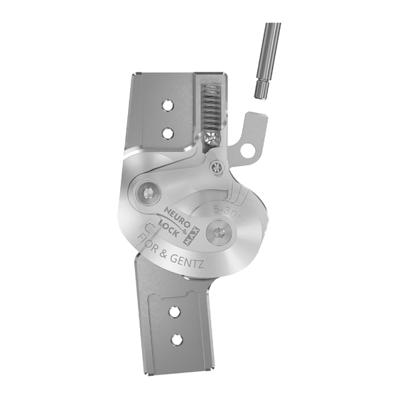
Systemkniegelenke
EN
Instructions for Use for Orthotists or Qualified/Trained Experts
System Knee Joints
NEURO LOCK
NEURO LOCK MAX
Download: www.fior-gentz.com
Notice d'utilisation pour les orthopédistes ou les experts qualifiés/formés
FR
Articulations de genou modulaires
Istruzioni per l'uso per tecnici ortopedici o professionisti qualificati/abilitati
IT
Articolazioni per ginocchio modulari
Instrucciones de uso para técnicos ortopédicos o expertos cualificados/capacitados
ES
Articulaciones de rodilla de sistema
NL
Gebruiksaanwijzing voor orthopedische technici of gekwalificeerde/opgeleide experts
Systeemkniegewrichtenn
Bruksanvisning for ortopediteknikere eller kvalifiserte/utdannede eksperter
NO
Systemkneledd
使用説明書 (装具士または有資格/訓練済みの専門職者向け)
JA
システム膝関節
NEURO FLEX MAX Sperrfunktion
Lock Function/Fonction de verrouillage/Funzione di
blocco/Función de bloqueo/vergrendelingsfunctie/
låsefunksjon/ロック機能
NEURO FLEX MAX Rastensperrfunktion
Step Lock Function/Fonction de verrouillage réglable
par crans/Funzione di blocco con denti di arresto/
Función de bloqueo por pasos/rustvergrendelings-
functie/inngrepslåsefunksjon/ステップロック機能
DE
Werbung
Kapitel
Inhaltsverzeichnis

Verwandte Anleitungen für FIOR & GENTZ NEURO LOCK


Inhaltszusammenfassung für FIOR & GENTZ NEURO LOCK
- Seite 1 NEURO LOCK NEURO FLEX MAX Sperrfunktion Lock Function/Fonction de verrouillage/Funzione di blocco/Función de bloqueo/vergrendelingsfunctie/ låsefunksjon/ロック機能 NEURO LOCK MAX NEURO FLEX MAX Rastensperrfunktion Step Lock Function/Fonction de verrouillage réglable par crans/Funzione di blocco con denti di arresto/ Función de bloqueo por pasos/rustvergrendelings- functie/inngrepslåsefunksjon/ステップロック機能...
- Seite 2 ..........................Seite 3 ........................... page 28 Druckdatum: 2020-03 Sie finden diese Gebrauchsanweisung im Download-Bereich unserer Website unter www.fior-gentz.de/downloads. Date printed: 2020-03 You can find these instructions for use in the download section on our website at www.fior-gentz.com/downloads Remarque : Vous trouverez cette notice d’utilisation dans la zone de téléchargement sur notre site web sous www.fior-gentz.de/fr/telechargements. Nota: Le presenti istruzioni per l'uso sono disponibili nell'area download del nostro sito all'indirizzo www.fior-gentz.com/downloads.
-
Seite 3: Inhaltsverzeichnis
2.2 Alle Hinweise für die sichere Verwendung des Systemkniegelenkes 3. Verwendungszweck 4. Gelenkfunktion 4.1 Alternativfunktion für NEURO FLEX MAX Sperrfunktion/Rastensperrfunktion: Begrenzung des maximalen Knieflexionswinkels 4.2 Alternativfunktion für NEURO LOCK: frei bewegliches, monozentrisches Systemgelenk mit integrierter Rückverlagerung 5. Lieferumfang 6. Belastbarkeit 7. Werkzeuge für die Montage des Systemgelenkes 8. -
Seite 4: Gebrauchsanweisung Für Orthopädietechniker Sytemkniegelenke
Gebrauchsanweisung für Orthopädietechniker Sytemkniegelenke Information Diese Gebrauchsanweisung richtet sich an Orthopädietechniker und enthält deshalb keine Hinweise auf Gefahren, die für Orthopädietechniker offensichtlich sind. Um ein Maximum an Sicherheit zu erreichen, weisen Sie bitte den Patienten und/oder das Versorgungsteam in die Anwendung und Pflege des Produktes ein. Für eine vereinfachte Darstellung werden alle Arbeitsschritte anhand des NEURO FLEX MAX Systemkniegelenkes mit Sperrfunktion (Abb. - Seite 5 WARNUNG Sturzgefahr durch unsachgemäße Handhabung Klären Sie den Patienten über die korrekte Verwendung des Systemgelenkes und mögliche Gefahren auf, insbesondere im Hinblick auf: - Feuchtigkeit und Wasser, - zu hohe mechanische Belastung (z. B. durch Sport, einen erhöhten Aktivitätsgrad, Gewichtszunahme) und - unbeabsichtigtes Entsperren des Systemgelenkes unter Flexionslast.
- Seite 6 WARNUNG Sturzgefahr durch falsch eingestellte Rastensperrfunktion Verwenden Sie für eine einwandfreie Rastensperrfunktion: - die 5° Rastenanschlagsscheibe mit dem 5° Extensionsanschlag, - die 0° Rastenanschlagsscheibe ohne Extensionsanschlag oder mit dem passenden 10°, 20° oder 30° Extensionsanschlag. WARNUNG Schädigung des anatomischen Gelenkes durch falsche Position des mechanischen Gelenkdrehpunktes Legen Sie die mechanischen Gelenkdrehpunkte richtig fest, um eine dauerhafte Fehlbelastung des anatomischen Gelenkes zu vermeiden.
-
Seite 7: Verwendungszweck
Klettern und Fallschirmspringen sind ausgeschlossen. Diese Gebrauchsanweisung bietet Informationen zu folgenden Systemkniegelenken: NEURO FLEX MAX Sperrfunktion NEURO LOCK NEURO LOCK MAX NEURO FLEX MAX Rastensperrfunktion Gelenkfunktion Alle Systemkniegelenke sind gesperrte Gelenke zur Bewegungsführung. Die Bewegungsfreiheit wird in 5° Extension begrenzt. Je nach verwendeten Systembauteilen gibt es für die Systemgelenke verschiedene... - Seite 8 Systembauteil Funktion Systemgelenk Flexionsan- Begrenzung des maxima- NEURO FLEX MAX Sperrfunktion schlagsscheibe AF len Knieflexionswinkels NEURO FLEX MAX Rastensperrfunktion (Alternativ funktion) Fixierstift Systemgelenke mit Fixierstift können durch die permanente Entsperrfuktion als frei bewegliches Gelenk mit integrierter Rückverlagerung verwendet werden (Abb. 2). Systembreite 12 mm 14 mm...
-
Seite 9: Begrenzung Des Maximalen Knieflexionswinkels
Der Extensionsanschlag und der Flexionsanschlag müssen immer pas- send zueinander eingestellt sein. Nach Austauschen des Extensionsan- 10° schlages (Abb. 4) ist der Flexionsanschlag entsprechend der gewählten 20° 30° Gradzahl einzufeilen. Dafür sind Hilfslinien am Flexionsanschlag vorhanden (Abb. 3/B). Möchten Sie das Systemgelenk mit einer geringeren Flexion nutzen, als Sie bereits eingefeilt haben, müssen Sie eine neue Flexionsanschlagsscheibe bzw. -
Seite 10: Alternativfunktion Für Neuro Lock: Frei Bewegliches, Monozentrisches
Alternativfunktion für NEURO LOCK: frei bewegliches, mono- zentrisches Systemgelenk mit integrierter Rückverlagerung Wird keine Sperrfunktion mehr benötigt, kann das NEURO LOCK Systemkniegelenk als frei bewegliches Gelenk mit integrierter Rückverlagerung verwendet werden (Abb. 8). Systembreite 14 mm 16 mm 20 mm Rückverlagerung der Gelenkachse... -
Seite 11: Belastbarkeit
Belastbarkeit Die Belastbarkeit ergibt sich aus den relevanten Patientendaten und kann über den Orthesen-Konfigurator bestimmt werden. Verwenden Sie zum Bau der Orthese die vom Orthesen-Konfigurator ermittelten Systembau- teile und beachten Sie die empfohlene Arbeitstechnik. Informationen zu den Arbeitstechniken finden Sie auf unserer Website www.fior-gentz.de im Bereich „Online-Tutorials“. -
Seite 12: Montage Des Systemgelenkes
Montage des Systemgelenkes Das Systemgelenk wird montiert geliefert. Alle Funktionen werden werk- seitig geprüft. Für den Einbau in die Orthese und für anfallende Wartungs- arbeiten müssen Sie das Systemgelenk demontieren. Um eine optimale Funktion zu gewährleisten, beachten Sie die nachfolgende Montageabfolge. Sichern Sie dabei alle Schrauben mit dem in Abschnitt 8.6 angegebenen Drehmoment. -
Seite 13: Montage Der Deckplatte
8 Setzen Sie die Gleitscheibe auf das Gelenkoberteil (Abb. 23). 9 Montieren Sie das Gelenkunterteil (Abb. 24). Achten Sie für eine vereinfachte Montage beim NEURO LOCK Systemkniegelenk darauf, dass das Gelenk flektiert ist. Einige NEURO LOCK Deckplatten haben aus fertigungstechnischen Gründen keine Senkung. -
Seite 14: Überprüfen Der Sperrfunktion
1 Sichern Sie die Schrauben der Deckplatte (Abb. 26) mit dem der Systembreite entsprechenden Drehmoment und LOCTITE® 243 mittelfest. 2 Lassen Sie den Kleber aushärten (nach ca. 24 Stunden endfest). Systembreite Schrauben für NEURO LOCK Deckplatte 14 mm 16 mm 20 mm... -
Seite 15: Einbau Der Hebelverlängerung
Einbau der Hebelverlängerung Die Hebelverlängerung dient der einfachen Entsperrung des Systemkniegelenkes. Beachten Sie, dass das NEURO LOCK Systemgelenk nur bilateral verbaut werden darf. Unilaterale Bauweise 1 Passen Sie die Hebelverlängerung an die Form der Orthese an und kürzen Sie sie bei Bedarf. -
Seite 16: Hinweise Zur Einwandfreien Funktion Der Orthese
Prüfen Sie den korrekten Sitz der Sperrklinke/Rastensperrklinke (siehe Abschnitt 8.5). Überprüfen Sie nach Einsetzen der Rastensperrklinke und der Rastenanschlagsscheibe, ob ein korrektes Einrasten der Rastensperr- klinke möglich ist. 11. Hinweise zur einwandfreien Funktion der Orthese Problem Ursache Maßnahme Der Patient muss die Körperlast Die Sperr- und Entsperrbauteile von der Orthese nehmen (z. B. -
Seite 17: Wartung
12. Wartung Überprüfen Sie das Systemgelenk alle 6 Monate auf Verschleiß und Funktionalität. Überprüfen Sie das System- gelenk bei der Versorgung von Kindern und Menschen mit kognitiven Einschränkungen alle 3 Monate. Prüfen Sie auch nach jeder durchgeführten Wartung die Funktionalität. Gelenkbauteil Problem Maßnahme... -
Seite 18: Austauschen Der Gleitscheiben
16 mm 10,5 10,2 10,5 H7 BP1110-L035 20 mm 10,5 10,5 11,5 11,2 11,5 H7 BP1211-L040 Bohr- und Reibmaße für NEURO LOCK MAX/NEURO FLEX MAX [mm] Reparatur- Reparatur- Splintbolzen Ø Maß zum Ø Maß zum Art.-Nr. Systembreite buchse buchse Ø außen Aufbohren... -
Seite 19: Ersatzteile
13. Ersatzteile Explosionszeichnung NEURO FLEX MAX Sperrfunktion/Rastensperrfunktion Abb. 38... -
Seite 20: Ersatzteile Für Das Neuro Lock Systemkniegelenk
Ersatzteile für das NEURO LOCK Systemkniegelenk Die Zuordnung der Positionen anhand der Explosionszeichnung der NEURO FLEX MAX Systemkniegelenke dient als Orientierungshilfe. Die Ersatzteile des NEURO LOCK Systemkniegelenkes sind nicht identisch zur Abbildung. Artikelnummer für Systembreite Pos. 14 mm 16 mm... - Seite 21 SK0492-VS SK0493-VS SK0493-VS Verbindungsschlauch für Hebelverlängerung Abb. ohne Linsenschraube zum Austauschen SC0403-L08 SC0403-L10 SC0403-L10 Abb. der Extensionsanschläge * Sperrklinken NEURO LOCK Artikelnummer für Systembreite 14 mm 16 mm 20 mm SK0473-TI038 SK0472-TI050 SK0473-TI050 SK0475-TI050 SK0472-TI063 SK0473-TI063 SK0475-TI063 SK0473-TI075 SK0475-TI075...
-
Seite 22: Ersatzteile Für Das Neuro Lock Max Systemkniegelenk
Ersatzteile für das NEURO LOCK MAX Systemkniegelenk Die Zuordnung der Positionen anhand der Explosionszeichnung der NEURO FLEX MAX Systemkniegelenke dient als Orientierungshilfe. Die Ersatzteile des NEURO LOCK MAX Systemkniegelenkes sind nicht identisch zur Abbildung. Artikelnummer für Systembreite Pos. 12 mm... -
Seite 23: Ersatzteile Für Das Neuro Flex Max Systemkniegelenk Sperrfunktion
Artikelnummer für Systembreite Pos. 12 mm 14 mm 16 mm 20 mm Bezeichnung Linsenschraube zum Aus- ohne SC0403-L08 SC0403-L08 SC0403-L10 SC0403-L10 tauschen der Extensionsan- Abb. schläge Ersatzteile für das NEURO FLEX MAX Systemkniegelenk Sperrfunktion Artikelnummer für Systembreite Pos. 12 mm 14 mm 16 mm 20 mm... - Seite 24 Linsenschraube zum Aus- ohne SC0403-L08 SC0403-L08 SC0403-L10 SC0403-L10 tauschen der Extensionsan- Abb. schläge * Sperrklinken NEURO LOCK MAX/NEURO FLEX MAX Sperrfunktion Artikelnummer für Systembreite 12 mm 14 mm 16 mm 20 mm Bein SK0771-L/025 SK0775-L/025 links lateral oder rechts medial...
-
Seite 25: Ersatzteile Für Das Neuro Flex Max Systemkniegelenk Rastensperrfunktion
Ersatzteile für das NEURO FLEX MAX Systemkniegelenk Rastensperrfunktion Artikelnummer für Systembreite Pos. 12 mm 14 mm 16 mm 20 mm Bezeichnung Splintbolzen (Rastensperr- SB6049-L0850 SB6049-L0950 SB6049-L1130 SB8559-L1290 klinke) SB7049-L0850 SB8559-L0950 SB9669-L1130 SB1069-L1290 Splintbolzen (Gelenkachse) SC2106-L04 SC2107-L04 SC9608-L11 SC9609-L04 Druckschraube FE1414-01 FE1520-01 FE1527-01 FE2726-01... - Seite 26 SK0762-R/088 SK0763-R/088 SK0765-R/088 links medial oder rechts lateral SK0762-R/100 SK0763-R/100 links medial oder rechts lateral *** Gleitscheiben NEURO LOCK MAX/NEURO FLEX MAX Artikelnummer für Systembreite 12 mm 14 mm 16 mm 20 mm Ø = 18 mm Ø = 20 mm Ø...
-
Seite 27: Entsorgung
14. Entsorgung Entsorgen Sie das Systemgelenk und dessen Einzelteile sachgerecht. Das Produkt darf nicht über den Hausmüll entsorgt werden (Abb. 39). Beachten Sie für die ordnungsgemäße Rück- führung der Wertstoffe die gültigen nationalen gesetzlichen Bestimmungen und örtlichen Vorschriften. Abb. 39 Für eine sachgerechte Entsorgung ist es notwendig, das Systemgelenk aus der Orthese auszubauen. - Seite 28 4. Joint Function 4.1 Alternative Function for NEURO FLEX MAX Lock Function/Step Lock Function: Limitation of the Maximum Knee Flexion Angle 4.2 Alternative Function for NEURO LOCK: Free Moving, Monocentric System Joint with Integrated Posterior Offset 5. Scope of Delivery 6.
-
Seite 29: Instructions For Use For Orthotists Or Qualified/Trained Experts System Knee Joints
Instructions for Use for Orthotists or Qualified/Trained Experts System Knee Joints Information These instructions for use are addressed to orthotists or qualified/trained experts and do not contain any notes about dangers which are obvious to orthotists or qualified/trained experts. To achieve maximum safety, please instruct the patient and/or care team in the use and maintenance of the product. - Seite 30 WARNING Risk of Falling Due to Improper Handling Inform the patient about the correct use of the system joint and potential dangers especially with regards - moisture and water; - excessive mechanical stress (e.g. due to sports, increased activity or weight gain) and - unintentional unlocking of the system joint under flexion load.
- Seite 31 WARNING Risk of Falling Due to Incorrectly Adjusted Step Lock Function For a properly working step lock function, use: - the 5° step lock stop disc with the 5° extension stop; - the 0° step lock stop disc without extension stop or with the corresponding 10°, 20° or 30° extension stop.
-
Seite 32: Application
Depending on the used system components, there are different functions for the system joints: System Component Function System Joint locating pin permanent unlocking of NEURO LOCK MAX the system knee joint NEURO FLEX MAX lock function NEURO FLEX MAX step lock function System Component Function... - Seite 33 Locating Pin System joints with locating pin can be used as free moving joint with an integrated posterior offset by means of the permanent unlock function (fig. 2). System Width 12mm 14mm 16mm 20mm Posterior Offset of the 12mm 14mm 16mm 20mm Joint Axis...
-
Seite 34: Alternative Function For Neuro Flex Max Lock Function/Step Lock Function
The extension stop and the flexion stop must always match each other. After replacing the extension stop (fig. 4), the flexion stop must be filed 10° according to the chosen degree. For this purpose, you will find auxiliary 20° 30° lines on the flexion stop (fig. -
Seite 35: Alternative Function For Neuro Lock: Free Moving, Monocentric System Joint With Integrated Posterior Offset
Alternative Function for NEURO LOCK: Free Moving, Mono- centric System Joint with Integrated Posterior Offset If the lock function is no longer needed, the NEURO LOCK system knee joint can be used as a free moving joint with integrated posterior offset (fig. 8). -
Seite 36: Load Capacity
Load Capacity The load capacity results from the relevant patient data and can be determined by using the Orthosis Config- urator. Use the system components determined by the Orthosis Configurator when producing an orthosis and mind the recommended production technique. You will find information on the production techniques in the section “Online Tutorials”... -
Seite 37: Assembly Instructions
Assembly Instructions The system joint is delivered fully assembled. All functions are checked beforehand. You have to disassemble the system joint for mounting it in the orthosis and for maintenance. To ensure an optimal functioning, follow the assembly instructions below. Secure all screws with the torque specified in paragraph 8.6. -
Seite 38: Mounting The Cover Plate
23 8 Place the sliding washer onto the joint’s upper part (fig. 23). 9 Mount the joint's lower part (fig. 24). For a simplified mounting to the NEURO LOCK system knee joint, make sure that the joint is flexed. -
Seite 39: Checking The Lock Function
1 Secure the screws for the cover plate (fig. 26) with the torque corresponding to the system width and LOCTITE® 243 medium strength. 2 Let the adhesive harden (final strength after approx. 24 hours). System Width Screws for NEURO LOCK Cover Plate 14mm 16mm 20mm... -
Seite 40: Mounting The Lever Extension
Mounting the Lever Extension The lever extension is used for an easy unlocking of the system knee joint. Please note that the NEURO LOCK system joint can only be mounted bilaterally. Unilateral Construction 1 Adapt the lever extension to the shape of the orthosis and shorten it, if necessary. -
Seite 41: Advice On Optimal Orthosis Functionality
11. Advice on Optimal Orthosis Functionality Problem Cause Measure The patient has to take the body The locking and unlocking parts weight off of the orthosis (e.g. by are still loaded. sitting down on a chair). The patient has to take the body weight off of the orthosis (e.g. -
Seite 42: Maintenance
2 Bore and ream the hole until it has reached the desired dimen- sion (fig. 34 and 35). 3 Insert the repair bushing made of a special plastic into the bore. fig. 34 fig. 35 Boring and Reaming Measurements for NEURO LOCK [mm] Repair Repair Ø Measure- Ø Measure-... -
Seite 43: Replacing The Sliding Washers
Boring and Reaming Measurements for NEURO LOCK MAX/NEURO FLEX MAX [mm] Repair Repair Ø Measure- Ø Measure- System Bearing Nut Art. No. Bushing Bushing ment for ment for Width Outer Ø Repair Bushing Inner Ø Outer Ø Boring Reaming 12mm 8.0 H7... -
Seite 44: Spare Parts
13. Spare Parts Exploded View Drawing NEURO FLEX MAX Lock Function/Step Lock Function fig. 38... - Seite 45 Spare Parts for the NEURO LOCK System Knee Joint The assignment of the items as shown in the exploded view drawing of the NEURO FLEX MAX system knee joints serves as guidance. The spare parts of the NEURO LOCK system knee joint are not identical to the picture.
- Seite 46 SK0492-VS SK0493-VS SK0493-VS connecting tube for lever extension fig. pan head screw for exchanging extension SC0403-L08 SC0403-L10 SC0403-L10 fig. stops * Locking Pawls NEURO LOCK Article Number for System Width 14mm 16mm 20mm SK0473-TI038 SK0472-TI050 SK0473-TI050 SK0475-TI050 SK0472-TI063 SK0473-TI063 SK0475-TI063...
- Seite 47 The assignment of the items as shown in the exploded view drawing of the NEURO FLEX MAX system knee joints serves as guidance. The spare parts of the NEURO LOCK MAX system knee joint are not identical to the picture.
- Seite 48 Article Number for System Width 12mm 14mm 16mm 20mm Description Item connecting tube for lever SK0492-VS SK0492-VS SK0493-VS SK0493-VS fig. extension pan head screw for SC0403-L08 SC0403-L08 SC0403-L10 SC0403-L10 fig. exchanging extension stops Spare Parts for the NEURO FLEX MAX System Knee Joint Lock Function Article Number for System Width 12mm 14mm...
- Seite 49 SC0403-L08 SC0403-L08 SC0403-L10 SC0403-L10 fig. ing extension stops * Locking Pawls NEURO LOCK MAX/NEURO FLEX MAX Lock Function Article Number for System Width 12mm 14mm 16mm 20mm SK0771-L/025 SK0775-L/025 left lateral or right medial...
- Seite 50 Spare Parts for the NEURO FLEX MAX System Knee Joint Step Lock Function Article Number for System Width Item 12mm 14mm 16mm 20mm Description SB6049-L0850 SB6049-L0950 SB6049-L1130 SB8559-L1290 bearing nut (step lock pawl) SB7049-L0850 SB8559-L0950 SB9669-L1130 SB1069-L1290 bearing nut (joint axis) SC2106-L04 SC2107-L04 SC9608-L11...
- Seite 51 SK0762-R/088 SK0763-R/088 SK0765-R/088 left medial or right lateral SK0762-R/100 SK0763-R/100 left medial or right lateral *** Sliding Washers NEURO LOCK MAX/NEURO FLEX MAX Article Number for System Width 12mm 14mm 16mm 20mm Ø = 18mm Ø = 20mm Ø...
-
Seite 52: Disposal
14. Disposal Dispose of the system joint and its individual parts properly. The product must not be dis- posed of with the residual waste (fig. 39). Please comply with the applicable national laws and local regulations for the proper recycling of recyclable materials. For proper disposal, it is necessary to demount the system joint from the orthosis. -
Seite 53: Informationen Für Die Versorgungsdokumentation Information For The Treatment Documentation
Informationen für die Versorgungsdokumentation Information for the Treatment Documentation Bitte heften Sie diese Gebrauchsanweisung zu Ihrer Versorgungsdokumentation! Add these instructions for use to your treatment documentation! Patientendaten I Patient Data Name I Name Straße I Address PLZ, Wohnort I Postcode, City Telefon privat I Home Telephone Telefon geschäftlich I Telephone at Work Kostenträger I Insurance... - Seite 54 Beinseite Leg Side links/left rechts/right Montierte Sperrklinke Mounted Locking Pawl SK ___________ - ____________ Montierte Rastensperrklinke Mounted Step Lock Pawl SK ___________ - ____________ Montierte Gleitscheibe Mounted Sliding Washer 1. GS ___________ - ________ 2. GS ___________ - ________ • •...