Inhaltsverzeichnis
Werbung
Verfügbare Sprachen
Verfügbare Sprachen
Werbung
Kapitel
Inhaltsverzeichnis

Verwandte Anleitungen für JUMO iTRON 04 B


Inhaltszusammenfassung für JUMO iTRON 04 B
- Seite 1 Typ 702050/0..Typ 702050/1..Typ 702050/2..J iTRON 04 B Kompakter Mikroprozessorregler Compact Microprocessor Controller Régulateur compact géré par microprocesseur B 70.2050.0 Betriebsanleitung Operating Instructions - Notice de mise en service 01.05/00419069...
- Seite 2 Bitte setzen Sie sich mit der nächsten Niederlassung oder mit dem Stammhaus in Verbindung. Bei technischen Rückfragen Telefon-Support Deutschland: Telefon: +49 661 6003-300 oder -653 oder -899 Telefax: +49 661 6003-881729 E-Mail: service@jumo.net Österreich: Telefon: +43 1 610610 Telefax: +43 1 6106140 E-Mail: info@jumo.at...
-
Seite 3: Inhaltsverzeichnis
Inhalt Geräteausführung identifizieren ..........4 Montage . -
Seite 4: Geräteausführung Identifizieren
Geräteausführung identifizieren Das Typenschild mit dem Bestellschlüssel ist auf der Seite des Gerätes aufgeklebt. Die angeschlossene Spannungs- versorgung muss mit der auf dem Typenschild angegebenen Spannung identisch sein. 702050 / . . . – . . . – . . . – . . / . . . Zubehör (1) Grundtypergänzung ®... -
Seite 5: Montage
Montage Setup- Schnittstelle ohne Betauung 1. Dichtung aufschieben 2. Gerät einsetzen 3. Befestigungselemente aufschieben 4. Schrauben gleichmäßig festziehen Dicht-an-dicht-Montage Mindestabstände der Schalttafelausschnitte: horizontal >14mm / vertikal >14mm... -
Seite 6: Elektrischer Anschluss
Elektrischer Anschluss 3.1 Installationshinweise Bei der Wahl des Leitungsmaterials, bei der Installation, bei der Absicherung und beim elektrischen Anschluss des Gerätes sind die Vorschriften der VDE 0100 "Bestimmungen über das Errichten von Starkstromanlagen mit Nennspannungen unter 1000 V" bzw. die jeweiligen Landesvorschriften zu beachten. Der elektrische Anschluss darf nur von Fachpersonal durchgeführt werden. -
Seite 7: Anschlussplan
3.2 Anschlussplan Signal- Signal- ausgang K2 ausgang K3 Reglerausgang K1 Der elektrische Anschluss Spannungs- Relais Relais Relais darf nur von Fachpersonal versorgung 250V/5A 250V/5A durchgeführt werden! 250V/5A lt. Typenschild (L-) (L+) N L1 Thermoelement – AC 110…240V Pt100 (3-Leiter) Istwerteingang AC/DC 20...53V 1. -
Seite 8: Bedienung
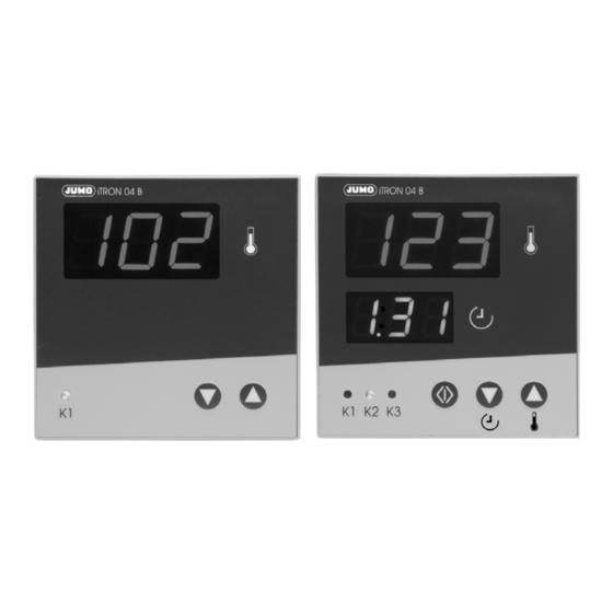
Bedienung 4.1 Anzeige- und Bedienelemente LED-Anzeige oben 20 mm hohe dreistellige 7-Segmentanzeige für Temperatur; rot Über das Setup-Programm kann hier der Sollwert angezeigt werden und mit einer Tastenkombination zwischen Istwert und Sollwert umgeschaltet werden. LED-Anzeige unten 14 mm hohe dreistellige 7-Segmentanzeige; grün Bei Typ 702050/1.. -
Seite 9: Bedienkonzept
4.2 Bedienkonzept... -
Seite 10: Bedienung Des Timers (Typ 702050/1
4.3 Bedienung des Timers (Typ 702050/1..) Timer starten Timer Timer aus Timer läuft Timer aus abgelaufen 1. Quittierung der Signalausgänge; nur wenn konfiguriert Timerzeit ändern Timer aus Timerzeit t1 ändern Timer aus Wird die Timerzeit bei laufenden Timer geändert, dann gilt diese Einstellung nur bis der Timer abgelaufen ist (temporäre Änderung)! (blinkt) -
Seite 11: Konfiguration
Konfiguration Time-Out: Wird 30 Sekunden lang keine Taste gedrückt, schaltet das Gerät automatisch in die Temperaturanzeige zurück. Parameter: Einzelne Parameter können im Parameterring nicht sichtbar sein, wenn sie mit dem Setup-Programm (Zubehör) deaktiviert wurden. In die Parameterebene wechseln mit (5 Sekunden lang gleichzeitig drücken!) Istwerteingang Wertebereich Parameter Bedeutung... - Seite 12 Ausgänge Wertebereich Parameter Bedeutung von...werkseitig...bis Zustand der Ausgänge im Fehlerfall 0 ...4... 7 Reglerausgang K1 Signalausgang K2 Signalausgang K3 Kapitel 6...
- Seite 13 Regler Wertebereich Parameter Bedeutung von...werkseitig...bis Reglerart/Wirksinn 0 ... 1 0 = Zweipunktregler invers (Heizen) / 1 = Zweipunktregler direkt (Kühlen) Untere Sollwertgrenze -99 ... +999 Ab dieser Grenze kann der Sollwert SP eingestellt werden. Obere Sollwertgrenze -99 ... +999 Bis zu dieser oberen Grenze kann der Sollwert SP eingestellt werden. Proportionalbereich 0...
- Seite 14 Wertebereich Parameter Bedeutung von...werkseitig...bis Schaltdifferenz 0,1 ... 1,0 ... 99,9 Für Regler mit 100% Arbeitspunkt (Grundlast) 0... 100% Stellgrad, wenn Istwert=Sollwert maximale Stellgradbegrenzung 0... 100% minimale Stellgradbegrenzung 0... 100%...
- Seite 15 Limitkomparator (bei Typ 702050/1.. und 702050/2..) Wertebereich Parameter Bedeutung von...werkseitig...bis Limitkomparatorfunktion 0 = ohne 1 = lk1 2 = lk2 3 = lk3 4 = lk4 5 = lk5 6 = lk6 7 = lk7 8 = lk8 lk1…lk6:Überwachung bezogen auf den Sollwert.
- Seite 16 Timer (nur bei Typ 702050/1..) Wertebereich Parameter Bedeutung von...werkseitig...bis Timerzeit 2 (Signalausgang K2) 0.00 ... 9.59 Werkseitig Signal über die gesamte Timerlaufzeit! (h.mm) oder (m.ss) (h=Stunden; m=Minuten; s=Sekunden) Funktion Signalausgang K2 0, 1, 2 0 = Quittierung mit Taste 1 = automatische Rücksetzung nach t1 2 = Signal ab Start bei t2E=0 bei t2E=1...
- Seite 17 Timerzeit 3 (Signalausgang K3) 0.00 ... 0.03 ... 9.59 (m.ss) m=Minuten / s=Sekunden Funktion Signalausgang K3 0, 1, 2 0 = Quittierung mit Taste 1 = automatische Rücksetzung nach t1 2 = Signal ab t1 bei t3E=0 bei t3E=1 Timerzeit t1 bei t3E=2 Timerzeit t1 t3 - Timerzeit Signalausgang K3 (0.01 ...
-
Seite 18: Alarmmeldungen
Alarmmeldungen In der Temperaturanzeige können folgende Alarmmeldungen angezeigt werden: Fehleranzeige Ursache Abhilfe Messbereichsüber-/ Sensor und Anschlussleitung auf Beschädigung -unterschreitung oder Kurzschluss überprüfen Fühler-/Leitungskurzschluss Überprüfen, ob der richtige Sensor eingestellt (Blinkt) oder angeschlossen ist Fühler-/Leitungsbruch Kapitel 5 „Konfiguration“ Diese Meldungen werden nur in der Temperaturanzeige ausgegeben. -
Seite 19: Technische Daten
Technische Daten Ausgänge Reglerausgang K1: Umschaltkontakt (Wechsler) Istwerteingang - Schaltleistung 5A bei 250V AC, ohmsche Last - Kontaktlebensdauer 250.000 Schaltungen Thermoelement bei Nennlast Fe-CuNi „J“ DIN EN 60 584 0 … 725°C (32 … 999°F) Signalausgänge Fe-CuNi „L“ 0 … 725°C (32 … 999°F) K2 + K3: Arbeitskontakt (Schließer) NiCr-Ni „K“... - Seite 20 Elektrische Daten Gehäuse Spannungsversorgung AC 110 ... 240V +10/-15%, Gehäuseart Kunststoffgehäuse 48 ... 63Hz oder für den Schalttafeleinbau AC/DC 20 ... 53V, 48 ... 63Hz nach DIN 43 700 Prüfspannung nach DIN EN 61 010, Frontmaß/Einbautiefe 96mm x 96mm / 68,5mm (Typprüfung) Teil 1 vom März 1994 Umgebungs-/Lager-...
-
Seite 22: Bedienungs- Und Konfigurationsübersicht
Bedienungs- und Konfigurationsübersicht... - Seite 23 Parameterebene (> 5s) 100% °C +999 = werkseitig 350s Dokumentieren Sie Ihre eigenen Einstellungen!
-
Seite 24: Mess- Und Regeltechnik Ag
JUMO GmbH & Co. KG JUMO JUMO Mess- und Regelgeräte Ges.m.b.H. Mess- und Regeltechnik AG Hausadresse: Moltkestraße 13 - 31 Pfarrgasse 48 Seestrasse 67, Postfach 36039 Fulda, Germany 1232 Wien, Austria 8712 Stäfa, Switzerland Lieferadresse: Telefon: +43 1 610610 Telefon: +41 1 928 24 44 Mackenrodtstraße 14... - Seite 25 Type 702050/0..Type 702050/1..Type 702050/2..J iTRON 04 B Compact Microprocessor Controller B 70.2050.0 Operating Instructions 01.05...
- Seite 26 Please read these Operating Instructions before commissioning the instrument. Keep the instructions in a place which is accessible to all users at all times. Please assist us to improve these instructions, where necessary. Your comments will be appreciated. All necessary settings are described in this manual. If any difficulties should still arise during commissioning, you are asked not to carry out any unauthorized manipulations on the unit.
- Seite 27 Contents Identifying the instrument version ......... . . 4 Installation .
-
Seite 28: Identifying The Instrument Version
Identifying the instrument version The nameplate with the order code is affixed to the housing side. The supply voltage that is connected must be iden- tical to the voltage specified on the nameplate. 702050 / . . . – . . . – . . . – . . / . . . Accessories (1) Basic type extension ®... -
Seite 29: Installation
Installation Setup interface no condensation 1. Push on seal 2. Insert instrument 3. Push on mounting brackets 4. Tighten screws evenly Side-by-side mounting Minimum spacings of panel cut-outs: horizontal >14mm / vertical >14mm... -
Seite 30: Electrical Connection
Electrical connection 3.1 Installation notes The choice of cable, the installation, the fusing and the electrical connection must conform to the requirements of VDE 0100 “Regulations on the installation of power circuits with nominal voltages below 1000 V” or the appropriate local regulations. -
Seite 31: Connection Diagram
3.2 Connection diagram... -
Seite 32: Operation
Operation 4.1 Displays and controls Upper LED display 20 mm high, 3-digit 7-segment display for temperature; red Using the setup program, you can display the setpoint here and use a key combination to switch between the setpoint and the process value. Lower LED display 14 mm high, 3-digit 7-segment display;... -
Seite 33: Principle Of Operation
4.2 Principle of operation... -
Seite 34: Timer Operation (Type 702050/1
4.3 Timer operation (type 702050/1..) Response to supply failure After the supply has been restored, the timer continues running, accurate to the minute. -
Seite 35: Configuration
Configuration Time-out If no key is pressed for 30 seconds, the controller will automatically return to the temperature display. Parameters Individual parameters will not be visible if they have been disabled in the parameter ring through the setup program (accessory). Change over to the parameter level using (hold both down for 5 seconds!) Process value input... - Seite 36 Outputs Value range Parameter Meaning from ... factory-set ... to State of the outputs in the event of an error 0 ... 4 ... 7 Controller output K1 Signal output K2 Signal output K3 Chapter 6...
- Seite 37 Controller Value range Parameter Meaning from ... factory-set ... to Controller type/control direction 0 ... 1 0 = 2-state controller, inverse (heating) / 1 = 2-state contr., direct (cooling) Lower setpoint limit -99 ... +999 The setpoint SP can be set starting from this limit. Upper setpoint limit -99 ...
- Seite 38 Value range Parameter Meaning from ... factory-set ... to Switching differential 0.1 ... 1.0 ... 99.9 for controllers with 100% Working point (basic load) 0... 100% Output level if process value=setpoint Maximum output level limiting 0... 100% Minimum output level limiting 0...
- Seite 39 Limit comparator (for types 702050/1.. and 702050/2..) Value range Parameter Meaning from ... factory-set ... to Limit comparator functions 0 = none 1 = lk1 2 = lk2 3 = lk3 4 = lk4 5 = lk5 6 = lk6 7 = lk7 8 = lk8 lk1…lk6: monitoring referred to...
- Seite 40 Timer (type 702050/1.. only) Value range Parameter Meaning from ... factory-set ... to Timer indication 2 (signal output K2) 0.00 ... 9.59 factory-set: signal from timer start throughout timer period! (h.mm) or (m.ss) (h = hours; m = minutes; s = seconds) Function for signal output K2 0, 1, 2 0 = acknowledgement through key...
- Seite 41 Timer indication 3 (signal output K3) 0.00 ... 0.03 ... 9.59 (m.ss) m = minutes / s = seconds Function for signal output K3 0, 1, 2 0 = acknowlegement through key 1 = automatic reset after t1 2 = signal from t1 If both signal output K3 and the limit comparator have been configured at the same time, both signals are switched through to the signal output K3 by means of a logic OR operation.
-
Seite 42: Alarm Messages
Alarm messages The following alarm messages can be displayed in the temperature display: Error message Cause Elimination overrange/ Check sensor and connection cable for damage underrange or short-circuit probe/lead break Check whether the correct sensor has been set (blinks) or connected probe/lead short-circuit Chapter 5 „Configuration“... -
Seite 43: Technical Data
Technical data Outputs Controller output K1: changeover contact Process value input - Contact rating 5A at 250V AC, resistive load - Contact life 250,000 operations at Thermocouple Range rated load Fe-Con J EN 60 584 0 to 725°C (32 to 999°F) Signal output K2 + K3: make contact (n.o.) Fe-Con L... - Seite 44 Electrical data Housing Supply voltage 110 - 240V AC +10/-15%, Housing type plastic housing for panel 48 - 63Hz, or mounting to DIN 43 700 20 - 53V AC/DC, 48 - 63Hz Bezel/ 96mm x 96mm / 68.5mm Depth behind panel Test voltages to EN 61 010, Part 1, (type test)
- Seite 46 Overview of operation and configuration...
- Seite 47 Parameter level (> 5s) 100% °C +999 = ex-factory 350s Make a record of your own settings!
- Seite 48 JUMO GmbH & Co. KG JUMO Instrument Co. Ltd. JUMO PROCESS CONTROL INC. Street adress: JUMO House 885 Fox Chase, Suite 103 Moltkestraße 13 - 31 Temple Bank, Riverway Coatesville PA 19320, USA 36039 Fulda, Germany Harlow, Essex CM20 2TT, UK...
- Seite 49 Type 702050/0..Type 702050/1..Type 702050/2..J iTRON 04 B Régulateur compact géré par microprocesseur B 70.2050.0 Notice de mise en service 01.05...
- Seite 50 03 87 37 53 00 Télécopieur : 03 87 37 89 00 E-Mail : info@jumo.net Service de soutien à la vente : 0892 700 733 (0,337 € /min) Tous les réglages et toutes les interventions éventuellement nécessaires sont décrits dans cette notice.
- Seite 51 Sommaire Identification de l’appareil ..........4 Montage .
-
Seite 52: Identification De L'appareil
Identification de l’appareil La plaque signalétique est collée sur la partie supérieure de l’appareil. La tension appliquée doit correspondre à celle indiquée sur la plaque signalétique. 702050 / . . – . . . – . . . – . . / . . . Accessoires (1) Extension du type de base ®... -
Seite 53: Montage
Montage Interface Setup sans dégivrage 1. Retirer le joint 2. Insérer l’appareil 3. Enlever les éléments de fixation 4. Serrer les vis Montage côte-à-côte Ecart min. de la découpe du tableau: horizontal >14mm / vertical >14mm... -
Seite 54: Raccordement Électrique
Raccordement électrique 3.1 Remarques à propose de l’installation Veuillez respecter la réglementation en vigueur aussi bien pour le choix du matériel des lignes, pour l’installation que pour le raccordement électrique de l’appareil. Le raccordement électrique ne doit être effectué que par du personnel qualifié. Débrancher les 2 conducteurs du réseau lorsque les pièces sous tension peuvent être touchées lors d’une inter- vention. -
Seite 55: Schéma De Raccordement
3.2 Schéma de raccordement Signal de Signal de sortie K2 sortie K3 Sortie r égulateur Le raccordement lectrique é Alimentation svt Relais Relais Relais ne peut tre effectu que ê é plaque signal tique é 250V/5A par du personnel qualifi ! é... -
Seite 56: Conduite
Conduite 4.1 Affichage et commande Indicateur à 3 chiffres à 7 segments de 20 mm de hauteur Affichage pour la température ; rouge. supérieur Le logiciel Setup permet d’afficher ici la consigne, il est possible de commuter entre valeur réelle et consigne au moyen d’une combinaison de touches Indicateur à... -
Seite 57: Concept D'utilisation
4.2 Concept d’utilisation R glage de la consigne é Affichage de la temp rature é 1.01 (clignote !) Version s oftware (exemple) > 5s ou automatiquement apr s 30s (Time-Out) è Niveau de param trage é Editer > 2s > 2s = incr menter la valeur é... -
Seite 58: Utilisation De La Fonction Timer (Minuterie) (Uniquement Type 702050/1.)
4.3 Utilisation de la fonction timer (minuterie) (uniquement type 702050/1.) D marrer la minuterie é Timer Timer OFF Timer OFF Timer en cours é coul é 1. Validation des signaux de sortie ; uniquement si configuré Modifier l’heure de la minuterie Modifier l’heure de Timer OFF... -
Seite 59: Configuration
Configuration Time-Out : Lorsqu’aucune touche n’est actionnée pendant 30 s, l’appareil réaffiche automatiquement la température. Paramètre : Les paramètres désactivés via le logiciel Setup (accessoire) ne pourront être affichés. Modifier au niveau de paramétrage à l’aide des touches (appuyer pendant 5 s !) Plage des valeurs Paramètre Signification de...d’usine...à... - Seite 60 Plage des valeurs Paramètre Signification de...d’usine...à Sorties Etat des sorties en cas d’erreur 0 à 4 à 7 Sortie de régulateur K1 Signal de sortie K2 Signal de sortie K3 désactivée désactivé désactivé activée désactivé désactivé désactivée activé désactivé activée activé...
- Seite 61 Plage des valeurs Paramètre Signification de...d’usine...à Bande proportionnelle 0à 999 Influence le comportement P du régulateur. Pour =0 l’algorithme du régulateur (par ex. PID) est inopérant. Temps de dérivée 0 à 80 à 999 s Influence le comportement D du régulateur. =0 le régulateur n’a pas de structure D.
- Seite 62 Plage des valeurs Paramètre Signification de...d’usine...à Limitation du taux de modulation 0 à 100% - taux de modulation maximal - taux de modulation minimal 0à 100% Alarme (uniquement pour type 702050/1. . et type 702050/2..) Fonction d’alarme 0 = sans 1 = lk1 2 = lk2 3 = lk3...
- Seite 63 Plage des valeurs Paramètre Signification de...d’usine...à Valeur limite de l’alarme -99 à 0 à +999 Différentiel de coupure de l’alarme 0,0 à 1,0 à 99,9 Timer (uniquement pour type 702050/1. !) Heure de la minuterie 2 (signal de sortie K2) 000 à...
- Seite 64 Plage des valeurs Paramètre Signification de...d’usine...à Heure de la minuterie 3 (signal de sortie K3) 000 à 003 à 959 (mss) m=minutes / s=secondes Fonction Signal de sortie K3 0, 1, 2 0 = validation à l’aide de la touche 1 = remise à...
-
Seite 65: Messages D'erreur
Messages d’erreur Les messages d’alarme suivants peuvent s’afficher dans l’indication de la température : Affichage Cause Remède Dépassement inf. / sup. de Vérifier que le capteur et le câble de raccord. ne l’étendue de mesure soient pas endommagé ou court-circuité Rupture / court-circuit de la Vérifier que le bon capteur soit réglé... -
Seite 66: Caractéristiques Techniques
Caractéristiques techniques Entrée valeur réelle : Sorties : Sortie de régulateur K1 : Thermocouple Etendue de mesure Contact inverseur ; 5A pour 250V AC, charge ohmique ; 250 000 coupures à charge nominale Fe-CuNi „J“ EN 60584 0 à 725°C (32 à 999°F) Fe-CuNi „L“... - Seite 67 Caractéristiques électriques Boîtier Tension d’alimentation 110 à 240V AC +10/-15%, Type de boîtier Boîtier en matière synthétique 48 à 63Hz ou pour montage sur tableau 20 à 53V AC/DC , 48 à63Hz suivant DIN 43 700 Tensions d’essai (essai suivant EN 61 010, partie 1 de Dimensions du cadre de type) mars 1994,...
- Seite 70 Aperçu de la commande et de la configuration R glage de la consigne é Affichage de la temp rature é 1.01 (clignote !) Version s oftware (exemple) > 5s ou automatiquement apr s 30s (Time-Out) è Niveau de param trage é...
- Seite 71 Niveau de paramétrage (> 5s) 100% °C +999 = réglage d’usine 350s Documentez vos propres réglages !
- Seite 72 JUMO GmbH & Co. KG JUMO Régulation S.A. JUMO AUTOMATION S.P.R.L. / P.G.M.B.H. / B.V.B.A Actipôle Borny Hausadresse: 7 rue des Drapiers Industriestraße 18 Moltkestraße 13 - 31 B.P. 45200 4700 Eupen, Belgique 36039 Fulda, Germany 57075 Metz - Cedex 3, France Téléphone :...