Danfoss PVG 32 Installationsanleitung
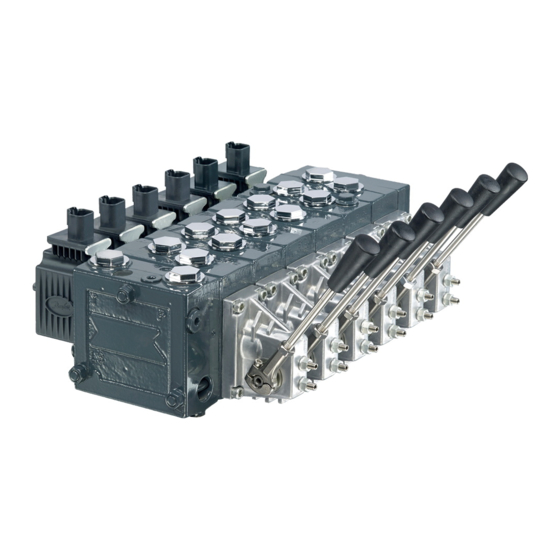
Proportional valve
Vorschau ausblenden
Andere Handbücher für PVG 32:
- Installationsanleitung (9 Seiten) ,
- Installationsanleitung (4 Seiten) ,
- Technische informationen (242 Seiten)
Quicklinks
Installation Guide
Proportional Valve
PVG 32
Identifikation, Identification
Standardmontage
: PVP til venstre for PVM
Standard installation : PVP to the left of PVM
Normale Montage
: PVP links von PVM
Montage standard
: PVP à gauche de PVM
F
E
PVM
Montering og orientering af stik
Installation and plug orientation
Montage und Ausrichtung des Steckers
Montage et orientation de la prise
PVB
1
2
L
82
130
mm
L
3.23
5.12
in
© Danfoss A/S, 2015-05
PVEH/
PVP
PVES
PVLP/PVLA
PVEA
PVB
PVEO
PVBZ
PVS
G
C
D
G
40 Nm
[354lbf•in]
A
N
B
N
LX
In particularly exposed applications, protection in the form
of screening of the electrical actuator is recommended
3
4
5
178
226
274
7.01
8.90
10.79
520L0412 • Rev CE • May 2015
PVH
PVMD
PVMR/
PVMF
V310165.A
L
PVS: 20Nm
[177lbf•in]
PVSI: 40 Nm
[354lbf•in]
M
A
1
B
1
4 x M8 x min.10
[4x 5/16-18 UNC min. x 0.39]
6
7
8
322
370
418
466
12.68
14.57
16.46
18.35
C: PVG-nummer, uge og år for montage
og serienummer
D: PVP-trykindstilling
E: PVP-nummer, uge og år for fremstilling
og serienummer
F: PVB - A-port, nummer, uge og år for
fremstilling og serienummer
G: PVM, uge og år for fremstilling
C: PVG-number, week and year of
installation and series number
D: PVP - pressure setting
E: PVP-number, week and year of
manufacturing and series number
F: PVB - A-port, number, week and year
of manufacturing and series number
G: PVM, week and year for manufacturing
C: PVG-Nummer, Woche und Jahr der
Montage und Seriennummer
D: PVP - Druckeinstellung
E: PVP-Nummer, Woche und Jahr der
Herstellung und Seriennummer
F: PVB - A-Anschluß, Nummer, Woche
und Jahr der Herstellung und Serien-
nummer
G: PVM, Woche und Jahr der Herstellung
C: PVG-numéro, semaine et année de
montage et numéro sériel
D: PVP - réglage de pression
E: PVP-numéro, semaine et année de
fabrication et numéro sériel
F: PVB - orifice-A, numéro, semaine et
année de fabrication et numéro sériel
G: Semaine et année de fabrication
V310139.A
* Plads til demontage
9
10
* Room for dismantling
514
* Platz für Demontage
20.24
* Espace pour démontage
V310115.A
1

Verwandte Anleitungen für Danfoss PVG 32


Inhaltszusammenfassung für Danfoss PVG 32
- Seite 1 * Plads til demontage * Room for dismantling * Platz für Demontage 3.23 5.12 7.01 8.90 10.79 12.68 14.57 16.46 18.35 20.24 * Espace pour démontage © Danfoss A/S, 2015-05 520L0412 • Rev CE • May 2015...
- Seite 2 300 bar [4351 psi] PVG 32 w. PVSI 350 bar [5076 psi] PVG 32 w. PVBZ 210 bar [3046 psi] PVG 32 w. HIC steel 350 bar [5076 psi] PVG 32 w. HIC aluminium 210 bar [3046 psi] PVG 120/32 w. PVS 300 bar [4351 psi] PVG 120/32 w.
- Seite 3 Relief valve 1 360º~120 bar 360º~100 bar 360º~1740 psi 360º~1450 psi V310149.A Before week 40/2003 Week 40/2003 - week 2/2004 After week 2/2004 Relief valve 1 Relief valve 2 © Danfoss A/S, 2015-05 520L0412 • Rev CE • May 2015...
-
Seite 4: Standard Mounting
F : Branch circuit for fault indication F : Anzapfung von der Fehlerüberwachung PVEM F : Prise du surveillance de défaut NC: Ikke tilsluttet PVEO NC: Not connected NC: Nicht eingeloggt NC: Pas connecté V310116.A 520L0412 • Rev CE • May 2015 © Danfoss A/S, 2015-05... - Seite 5 (pin 2) = 0.5 • U Q: P -> A (pin 2) = (0.5 -> 0.25) • U Q: P -> B (pin 2) = (0.5 -> 0.75) • U © Danfoss A/S, 2015-05 520L0412 • Rev CE • May 2015...
- Seite 6 E : Interrupteur d’arrêt d’urgence F : Udtag fra fejlovervågning F : Branch circuit for fault indication F : Anzapfung von der Fehlerüberwachung F : Prise du surveillance de défaut 520L0412 • Rev CE • May 2015 © Danfoss A/S, 2015-05...
- Seite 7 (pin 1) = 0.5 • U (pin 1) = (0.5 -> 0.75) • U Q: P -> A Q: P -> B (pin 1) = (0.5 -> 0.25) • U © Danfoss A/S, 2015-05 520L0412 • Rev CE • May 2015...
-
Seite 8: Block Diagram
B: Electrodistributeur Fejltilstand Error condition Fehlerzustand Condition erronée Aktiv fejlovervågning Active fault monitoring Aktive Fehlerüberwachung Active défault monitoring Passiv fejlovervågning Passive fault monitoring Passive Fehlerüberwachung Passiv défault monitoring Block diagram 520L0412 • Rev CE • May 2015 © Danfoss A/S, 2015-05... - Seite 9 Transducer omdrejning Håndtagsbevægelse Turn of transducer Movement of lever Transducerdrehung Hebelbewegung Rotation du transducteur Mouvement du manipulateur 1.5 mm [0.06 in] 3.0 mm [0.12 in] 4.5 mm [0.18 in] © Danfoss A/S, 2015-05 520L0412 • Rev CE • May 2015...
- Seite 10 Abschirmung empfohlen. Dans les zones particulièrement lignende. particularly moist conditions. exposées, il est cependant conseillé de protéger le PVE à l’aide d’un écran ou d’un dispositif similaire. 520L0412 • Rev CE • May 2015 © Danfoss A/S, 2015-05...