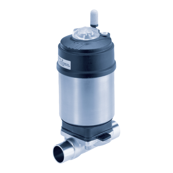
bürkert 2103 Bedienungsanleitung
Kolbengesteuertes membranventil
Vorschau ausblenden
Andere Handbücher für 2103:
- Bedienungsanleitung (142 Seiten) ,
- Schnellstartanleitung (53 Seiten) ,
- Kurzanleitung (43 Seiten)

Verwandte Anleitungen für bürkert 2103


Inhaltszusammenfassung für bürkert 2103
- Seite 43 Typ 2103, 2104, 2105 Kolbengesteuertes Membranventil Typ 2103, 2104, 2105 Durchflusswerte und Kennlinien ..........61 1 DIE BEDIENUNGSANLEITUNG ............44 Allgemeine Technische Daten ..........67 Darstellungsmittel ..............44 Begriffsdefinition Produkt ............44 8 MONTAGE ..................... 68 Sicherheitshinweise ..............68 2 BESTIMMUNGSGEMÄSSE VERWENDUNG........ 45 Einbaulage allgemein ..............68 Beschränkungen ..............45 Einbaulage 2/2-Wege-Ventil Typ 2103 ......68...
-
Seite 44: Die Bedienungsanleitung
▶ Bei Nichtbeachtung sind Tod oder schwere Verletzungen die Folge. 1.2 Begriffsdefinition Produkt WARNUNG! Der in dieser Anleitung verwendeten Begriff „Produkt“ steht immer Warnt vor einer möglicherweise gefährlichen Situation! für das kolbengesteuerte Membranventil Typ 2103, 2104 oder ▶ Bei Nichtbeachtung drohen schwere Verletzungen oder Tod. 2105. deutsch... -
Seite 45: Bestimmungsgemässe Verwendung
Typ 2103, 2104, 2105 BestimmungsgemäßeVerwendung BESTIMMUNGSGEMÄSSE GRUNDLEGENDE VERWENDUNG SICHERHEITSHINWEISE Diese Sicherheitshinweise berücksichtigen keine Bei nicht bestimmungsgemäßem Einsatz des Membranventils Typ 2103, 2104 oder 2105 können Gefahren für Personen, • Zufälligkeiten und Ereignisse, die bei Montage, Betrieb und Wartung Anlagen in der Umgebung und die Umwelt entstehen. der Produkte auftreten können. ▶ Das Produkt ist für die Steuerung des Durchflusses von flüssigen •... -
Seite 46: Allgemeine Hinweise
4.3 Informationen im Internet • Ventil nicht mechanisch belasten (z. B. durch Ablage von Gegen- ständen oder als Trittstufe). Bedienungsanleitungen und Datenblätter zum Typ 2103, 2104 und • Keine äußerlichen Veränderungen an den Ventilen vornehmen. 2105 finden Sie im Internet unter: www.buerkert.de Gehäuseteile und Schrauben nicht lackieren. -
Seite 47: Produktbeschreibung
• Ansteuereinheit Je nach Anforderung stehen Ansteuereinheiten verschiedener 5.2 Ausführungen Ausführungen zu Verfügung. Typ 2103, 2104 und 2105 gibt es in 2 Ausführungen. • Hubbegrenzung Begrenzung der maximalen Offenstellung / Durchflussmenge • Standardausführung – ohne separates Ex-Typschild. mittels Einstellschraube. Die Standardausführung darf nicht im explosionsgefährdeten •... -
Seite 48: Vorgesehener Einsatzbereich
Typ 2103, 2104, 2105 AufbauundFunktion 5.4 Vorgesehener Einsatzbereich AUFBAU UND FUNKTION Das Membranventil Typ 2103, 2104 oder 2105 ist für die Steuerung 6.1 Aufbau von verschmutzten, aggressiven, abrasiven, hochreinen oder sterilen Medien konzipiert. Es dürfen nur Medien gesteuert werden, die die Das kolbengesteuerte Membranventil besteht aus einem pneuma- Gehäuse und Dichtwerkstoffe (siehe Typschild) nicht angreifen. - Seite 49 Typ 2103, 2104, 2105 AufbauundFunktion 6.1.2 T-Ventil Typ 2104 6.1.3 Bodenablassventil Typ 2105 Zweiter Steuerluftanschluss für SFI Bodenablassgehäuse und Entlüftungsanschluss für SFA und SFB mit Schweißflansch Steuerluftanschluss für Steuerfunktion (SF) A, B, I VA-Membransockel Klarsichthaube mit Stellungsanzeige Antriebsdeckel Antriebsgehäuse Antriebsgehäuse Antriebsdeckel Klarsichthaube mit Stellungsanzeige...
-
Seite 50: Funktion
Typ 2103, 2104, 2105 AufbauundFunktion 6.2 Funktion Steuerfunktion I (SFI) Stellfunktion über wechselseitige Federkraft (SFA) oder pneumatischer Steuerdruck (SFB und SFI) Druckbeaufschlagung. erzeugen die Schließkraft des Membrandruckstücks. Über eine Spindel, die mit dem Antriebskolben verbunden ist, wird die Kraft übertragen. 6.2.1 Steuerfunktionen (SF) -
Seite 51: Technische Daten
/ Antriebsgröße) Mediumsdruck beachten. Zulässiger 7.1 Konformität Steuerdruck Steuerfunktion Das Membranventil Typ 2103, 2104 und 2105 ist konform zu den CE-Kennzeichnung EG-Richtlinien entsprechend der EG-Konformitätserklärung. 7.2 Normen 2103 A 20M PTFE VS Pilot 4,8-10bar Tamb 0°C - +60°C Pmed 10,0bar Die angewandten Normen, mit denen die Konformität mit den EG-... -
Seite 52: Beschriftung Schmiedegehäuse
Typ 2103, 2104, 2105 TechnischeDaten 7.3.2 Beschriftung Schmiedegehäuse 7.4 Betriebsbedingungen Chargennummer 7.4.1 Temperaturbereiche XX F Werkstoff Zulässige Umgebungstemperatur für Antriebe Fertigungsnummer / Antriebsgröße Antriebswerkstoff Umgebung Seriennummer XXXXXXXX/XXX ø 50 mm 1.4435/316L(VS) XXXX Code Oberflächengüte PN16/CWP150 XXXXXX ø 70 mm 0 ... +60 °C kundenspezifischer Text 0 ... -
Seite 53: Druckbereiche
Typ 2103, 2104, 2105 TechnischeDaten Zulässige Mediumstemperatur für Membranen Antriebsgröße Steuerdruck Die angegebenen Mediumstemperaturen gelten nur für ø 50 mm Medien, welche die Membranwerkstoffe nicht angreifen oder ø 70 mm aufquellen lassen. 5,5 ... 7,0 bar ø 90 mm Das Verhalten des Mediums gegenüber der Membran kann sich durch die Mediumstemperatur verändern. - Seite 54 Typ 2103, 2104, 2105 TechnischeDaten Steuerdruck bei Steuerfunktion A Mediumsdruck bei Steuerfunktion A Die Werte sind gültig für Gehäuse aus Steuerdruck [bar] Antriebs- Nennweite • Schmiedestahl (VS) größe DN (Membran- bei Mediumsdruck [mm] größe) [mm] • Feinguss (VG) 0 bar maximal 8 EPDM / FKM Max. dichtgehaltener Mediumsdruck [bar] ø 50 8 PTFE Druck einseitig...
- Seite 55 Mediumsdruck dargestellt. Die Werte sind gültig für Gehäuse aus • Schmiedestahl (VS) • Feinguss (VG) Bei Einsatz des Typs 2103, 2104 oder 2105 als Regelventil Steuerdruck [bar] gibt es teilweise abweichende Druckverhältnisse. Diese sind Bild 7: Druckdiagramm, Antrieb ø 70 mm, Steuerfunktion B, in den Diagrammen mit grauem Hintergrund dargestellt.
- Seite 56 Typ 2103, 2104, 2105 TechnischeDaten ø 90 EPDM ø 130 EPDM Steuerdruck [bar] Steuerdruck [bar] Bild 9: Druckdiagramm, Antrieb ø 90 mm, Steuerfunktion B, Bild 11: Druckdiagramm, Antrieb ø 130 mm, Steuerfunktion B, Elastomer-Membran Elastomer-Membran Diagramm für Regelventil Diagramm für Regelventil ø 90 EPDM / Regelventil ø 130 EPDM / Regelventil DN50 Steuerdruck [bar] Steuerdruck [bar] Bild 10: Druckdiagramm für Regelventil, Antrieb ø...
- Seite 57 Typ 2103, 2104, 2105 TechnischeDaten Steuerfunktion B / PTFE-Elastomer-Membran ø 70 PTFE ø 50 PTFE Steuerdruck [bar] Steuerdruck [bar] Bild 14: Druckdiagramm, Antrieb ø 70 mm, Steuerfunktion B, Bild 13: Druckdiagramm, Antrieb ø 50 mm, Steuerfunktion B, PTFE-Elastomer-Membran PTFE-Elastomer-Membran Diagramm für Regelventil ø 70 PTFE / Regelventil Steuerdruck [bar] Bild 15: Druckdiagramm für Regelventil, Antrieb ø 70 mm,...
- Seite 58 Typ 2103, 2104, 2105 TechnischeDaten ø 90 PTFE ø 130 PTFE Steuerdruck [bar] Steuerdruck [bar] Bild 16: Druckdiagramm, Antrieb ø 90 mm, Steuerfunktion B, Bild 18: Druckdiagramm, Antrieb ø 130 mm, Steuerfunktion B, PTFE-Elastomer-Membran PTFE-Elastomer-Membran Diagramm für Regelventil Diagramm für Regelventil ø 90 PTFE / Regelventil ø 130 PTFE / Regelventil DN40 DN50 Steuerdruck [bar] Steuerdruck [bar] Bild 17: Druckdiagramm für Regelventil, Antrieb ø...
- Seite 59 Typ 2103, 2104, 2105 TechnischeDaten Steuerfunktion I / Elastomer-Membran ø 50 EPDM ø 90 EPDM Steuerdruck [bar] Steuerdruck [bar] Bild 20: Druckdiagramm, Antrieb ø 50 mm, Steuerfunktion I, Bild 22: Druckdiagramm, Antrieb ø 90 mm, Steuerfunktion I, Elastomer-Membran Elastomer-Membran ø 70 EPDM ø 130 EPDM Steuerdruck [bar] Steuerdruck [bar] Bild 21: Druckdiagramm, Antrieb ø 70 mm, Steuerfunktion I, Bild 23: Druckdiagramm, Antrieb ø...
- Seite 60 Typ 2103, 2104, 2105 TechnischeDaten Steuerfunktion I / PTFE-Elastomer-Membran ø 50 PTFE ø 90 PTFE Steuerdruck [bar] Steuerdruck [bar] Bild 24: Druckdiagramm, Antrieb ø 50 mm, Steuerfunktion I, Bild 26: Druckdiagramm, Antrieb ø 90 mm, Steuerfunktion I, PTFE-Elastomer-Membran PTFE-Elastomer-Membran ø 70 PTFE ø 130 PTFE Steuerdruck [bar] Steuerdruck [bar] Bild 25: Druckdiagramm, Antrieb ø 70 mm, Steuerfunktion I, Bild 27: Druckdiagramm, Antrieb ø...
-
Seite 61: Durchflusswerte Und Kennlinien
Typ 2103, 2104, 2105 TechnischeDaten Durchflusskennlinien für DN8 7.5 Durchflusswerte und Kennlinien (für Ventile mit 2/2-Wege-Ventilgehäuse) Durchflusswerte für DN8 Schmiedegehäuse (VS) Gussgehäuse (VG) EPDM PTFE EPDM PTFE Kv-Wert 0,21 0,26 Hub [%] 0,04 0,42 Bild 28: Durchflusskennlinien für DN8 0,64 0,14 0,73 0,36 0,88 0,29 0,88 0,52 1,09 0,45 1,08 0,65 1,23... - Seite 62 Typ 2103, 2104, 2105 TechnischeDaten Durchflusswerte für DN15 Durchflusskennlinien für DN15 Schmiedegehäuse (VS) Gussgehäuse (VG) EPDM PTFE EPDM PTFE Kv-Wert 0,13 0,58 0,48 0,93 1,42 0,24 1,15 1,93 2,23 1,04 1,87 2,68 1,97 2,61 3,55 2,97 3,47 Hub [%] 3,98 4,04 Bild 29: Durchflusskennlinien für DN15 4,51...
- Seite 63 Typ 2103, 2104, 2105 TechnischeDaten Durchflusswerte für DN20 Durchflusskennlinien für DN20 Schmiedegehäuse (VS) Gussgehäuse (VG) EPDM PTFE EPDM PTFE Kv-Wert 0,50 0,40 0,10 0,60 0,80 0,30 Hub [%] Bild 30: Durchflusskennlinien für DN20 10,5 10,3 10,7 10,5 Tab. 10: Durchflusswerte für DN20 deutsch...
- Seite 64 Typ 2103, 2104, 2105 TechnischeDaten Durchflusswerte für DN25 Durchflusskennlinien für DN25 Schmiedegehäuse (VS) Gussgehäuse (VG) EPDM PTFE EPDM PTFE Kv-Wert 0,43 0,33 0,71 0,35 0,95 0,71 Hub [%] 10,5 10,5 Bild 31: Durchflusskennlinien für DN25 11,8 10,0 12,2 12,3 11,2 13,0 11,9 12,7 11,6 14,1 13,0 13,1...
- Seite 65 Typ 2103, 2104, 2105 TechnischeDaten Durchflusswerte für DN40 Durchflusskennlinien für DN40 Schmiedegehäuse (VS) Gussgehäuse (VG) EPDM PTFE EPDM PTFE Kv-Wert 14,7 14,9 15,3 15,4 20,1 20,2 21,6 21,4 22,3 23,6 24,4 Hub [%] 23,4 26,2 26,1 Bild 32: Durchflusskennlinien für DN40 25,4 25,5 29,1 27,6 27,4 32,2...
- Seite 66 Typ 2103, 2104, 2105 TechnischeDaten Durchflusswerte für DN50 Durchflusskennlinien für DN50 Schmiedegehäuse (VS) Gussgehäuse (VG) EPDM PTFE EPDM PTFE Kv-Wert 2,68 1,88 4,21 3,56 11,9 10,4 10,4 11,5 21,6 18,4 20,9 20,7 30,4 29,2 30,3 37,8 36,3 35,2 36,1 Hub [%] 41,1 39,4 Bild 33: Durchflusskennlinien für DN50...
-
Seite 67: Allgemeine Technische Daten
Typ 2103, 2104, 2105 TechnischeDaten 7.6 Allgemeine Technische Daten Anschlüsse Steuerluftanschluss Schlauchsteckverbinder 6/4 mm bzw. 1/4” Steuerfunktionen (SF) weitere auf Anfrage Steuerfunktion A In Ruhestellung Leitungsanschluss Schweißanschluss: nach EN ISO 1127 durch Federkraft geschlossen (ISO 4200), DIN 11850 R2 Steuerfunktion B In Ruhestellung andere Anschlüsse auf Anfrage... -
Seite 68: Montage
Typ 2103, 2104, 2105 Montage MONTAGE 8.2 Einbaulage allgemein Einbau für Selbstentleerung des Gehäuses 8.1 Sicherheitshinweise Die Sicherstellung der Selbstentleerung liegt in der Verant- wortung des Installateurs und Betreibers. GEFAHR! Verletzungsgefahr durch hohen Druck in der Anlage! Einbau für Leckagedetektion ▶ Vor dem Lösen von Leitungen und Ventilen den Druck abschal- ten und Leitungen entlüften. -
Seite 69: Einbaulage T-Ventil Typ 2104
Typ 2103, 2104, 2105 Montage 8.6 Vor dem Einbau Markierung • Vor dem Anschluss des Ventils auf fluchtende Rohrleitungen achten. • Die Durchflussrichtung ist beliebig. α 8.6.1 Vorbereitende Arbeiten Winkel α: 10° bis 40° → Rohrleitungen von Verunreinigungen säubern (Dichtungsmaterial, Neigung zur Leitungsachse 1° ... 5°... -
Seite 70: Einbau
Typ 2103, 2104, 2105 Montage 8.7 Einbau Antrieb vom Ventilgehäuse demontieren: HINWEIS! Beim Einsatz in aggressiver Umgebung empfehlen wir, sämt- liche freien Pneumatikanschlüsse mit Hilfe eines Pneumatik- Beschädigung der Membran bzw. der Sitzkontur! schlauchs in neutrale Atmosphäre abzuleiten. ▶ Das Ventil muss sich bei der Demontage des Antriebs in geöff- neter Stellung befinden. -
Seite 71: Antrieb Montieren (Schweißgehäuse)
Typ 2103, 2104, 2105 Montage → Das Ventil gleichmäßig innerhalb und außerhalb des Behälters Für Informationen über Behälter und Schweißanweisungen unter Zufuhr von Gas und mit dem Ventil-Edelstahl 316L kompa- beziehen Sie sich auf die Norm ASME VIII Division I. -
Seite 72: Antrieb Ausrichten
Typ 2103, 2104, 2105 Montage Montage für Antrieb mit Steuerfunktion B und I: 8.7.4 Antrieb ausrichten → Die Gehäuseschrauben ohne Druckbeaufschlagung über Kreuz Bei Ventilen mit VA-Membransockel kann der Antrieb zum leicht anziehen, bis die Membran zwischen Gehäuse und Antrieb Ventilgehäuse um 360 ° stufenlos gedreht werden. anliegt. Schrauben noch nicht festziehen. -
Seite 73: Pneumatischer Anschluss
Typ 2103, 2104, 2105 Montage 8.8 Pneumatischer Anschluss zur Reduzierung der Abluftlautstärke lose mitgeliefert. → Schalldämpfer in den freien Entlüftungsanschluss 2 stecken GEFAHR! (siehe „Bild 39: Pneumatischer Anschluss“). Verletzungsgefahr durch hohen Druck in der Anlage! Beim Einsatz in aggressiver Umgebung empfehlen wir, ▶ Vor dem Lösen von Leitungen und Ventilen den Druck abschal- sämtliche freien Pneumatikanschlüsse mit Hilfe eines... -
Seite 74: Demontage
Typ 2103, 2104, 2105 ElektrischeAnsteuerung 8.9 Demontage ELEKTRISCHE ANSTEUERUNG GEFAHR! Das Ventil Typ 2103, 2104 und 2105 ist mit folgenden Ansteue- Verletzungsgefahr durch Mediumsaustritt und Druckentladung! rungen kombinierbar: Der Ausbau eines Produkts, das unter Druck steht, ist wegen • Typ 8690 Pneumatische Ansteuerung plötzlicher Druckentladung oder Mediumsaustritt gefährlich. -
Seite 75: Wartung, Reinigung
Typ 2103, 2104, 2105 Wartung,Reinigung WARTUNG, REINIGUNG WARNUNG! Bei Steuerfunktion I – Gefahr bei Steuerdruckausfall! 10.1 Sicherheitshinweise Bei Steuerfunktion I erfolgt die Ansteuerung und Rückstellung pneumatisch. Bei Druckausfall wird keine definierte Position erreicht. GEFAHR! ▶ Für einen kontrollierten Wiederanlauf das Produkt zunächst mit Verletzungsgefahr durch hohen Druck in der Anlage! Steuerdruck beaufschlagen, danach erst das Medium aufschalten. -
Seite 76: Lebensdauer Der Membran
Typ 2103, 2104, 2105 Wartung,Reinigung 10.2.3 Kontrollintervalle 10.2.5 Reinigung → Membran nach maximal 10 Schaltspielen auf Verschleiß prüfen. Zur Reinigung von außen können handelsübliche Reinigungsmittel verwendet werden. Schlammartige und abrasive Medien erfordern entspre- HINWEIS! chend kürzere Kontrollintervalle! Vermeidung von Schäden durch Reinigungsmittel. ▶ Die Verträglichkeit der Mittel mit den Gehäusewerkstoffen und 10.2.4 Lebensdauer der Membran... -
Seite 77: Instandhaltung
Typ 2103, 2104, 2105 Instandhaltung INSTANDHALTUNG WARNUNG! Bei Steuerfunktion I – Gefahr bei Steuerdruckausfall! 11.1 Sicherheitshinweise Bei Steuerfunktion I erfolgt die Ansteuerung und Rückstellung pneumatisch. Bei Druckausfall wird keine definierte Position GEFAHR! erreicht. Verletzungsgefahr durch hohen Druck in der Anlage! ▶ Für einen kontrollierten Wiederanlauf das Produkt zunächst ▶ Vor dem Lösen von Leitungen und Ventilen den Druck abschal- mit Steuerdruck beaufschlagen, danach erst das Medium aufschalten. - Seite 78 Typ 2103, 2104, 2105 Instandhaltung → Die Gehäuseschrauben einsetzen und über Kreuz leicht anziehen, GEFAHR! bis die Membran zwischen Gehäuse und Antrieb anliegt. Schrauben noch nicht festziehen. Verletzungsgefahr durch Mediumsaustritt und Druckentladung! → Das Membranventil zweimal schalten. Der Ausbau eines Produkts, das unter Druck steht, ist wegen →...
- Seite 79 Typ 2103, 2104, 2105 Instandhaltung Austausch bei Steuerfunktion B und I Nennweite DN Anziehdrehmomente für Membranen [Nm] → Das Ventilgehäuse in eine Haltevorrichtung einspannen (Membrangröße) EPDM/FKM PTFE/ (gilt nur für noch nicht eingebaute Ventile). advanced PTFE/ → Die vier Gehäuseschrauben lösen. kaschierte advanced PTFE → Den Antrieb vom Gehäuse abnehmen. → Alte Membran ausknöpfen oder ausschrauben. Bei Befestigung mit Bajonettverschluss die Membran durch Drehen um 90°...
-
Seite 80: Störungen
Mediumsdruck zu hoch – verwenden. dicht siehe Druckangabe auf dem Typschild. Steuerdruck zu gering – Als Ersatzteil für das kolbengesteuerte Membranventil Typ 2103, siehe Druckangabe auf dem Typschild. 2104 und 2105 ist die Membran erhältlich. Durchflussmenge PTFE Membran ausgebeult →... -
Seite 81: Ersatzteilsätze
Typ 2103, 2104, 2105 Ersatzteile 13.1 Ersatzteilsätze Nennweite (Membrangröße) Bestellnummern für Membranen [mm] EPDM (AB*) EPDM (AD*) FKM (FF*) 677 663 688 421 677 684 677 664 688 422 677 685 677 665 688 423 677 686 677 667 688 424 677 687 Membran 677 668... -
Seite 82: Transport, Lagerung, Verpackung
Typ 2103, 2104, 2105 Transport,Lagerung,Verpackung TRANSPORT, LAGERUNG, VERPACKUNG HINWEIS! Transportschäden! Unzureichend geschützte Geräte können durch den Transport beschädigt werden. • Gerät vor Nässe und Schmutz geschützt in einer stoßfesten Verpackung transportieren. • Eine Über- bzw. Unterschreitung der zulässigen Lagertempe- ratur vermeiden. - Seite 124 Type 2103, 2104, 2105 français...
- Seite 126 www.burkert.com...