Herunterladen Inhalt Inhalt Diese Seite drucken

Werbung

Verfügbare Sprachen
  • DE

Verfügbare Sprachen

  • DEUTSCH, seite 94
FANTASY - FATA
SIRENA - STORY
I
Installazione, uso e manutenzione
UK
Installation, use and maintenance
F
Installation, usage et maintenance
E
Instalación, uso y mantenimiento
D
Installations-, Betriebs- und Wartungsanleitung
NL
Installatie, gebruik en onderhoud
- 1
-
pag.
2
pag. 25
pag. 48
pag. 71
pag.
94
pag. 117

Werbung

Inhaltsverzeichnis
loading

Inhaltszusammenfassung für EdilKamin FANTASY

  • Seite 1 FANTASY - FATA SIRENA - STORY Installazione, uso e manutenzione pag. Installation, use and maintenance pag. 25 Installation, usage et maintenance pag. 48 Instalación, uso y mantenimiento pag. 71 Installations-, Betriebs- und Wartungsanleitung pag. Installatie, gebruik en onderhoud pag. 117...
  • Seite 2 Presso il rivenditore, sul sito www.edilkamin.com o al numero verde può trovare il nominativo del Centro Assistenza più vicino. La scrivente EDILKAMIN S.p.a. con sede legale in Via Vincenzo Monti 47 - 20123 Milano - Cod. Fiscale P.IVA 00192220192 STUFE A PELLET, a marchio commerciale EDILKAMIN, denominate FANTASY - FATA - SIRENA - STORY...
  • Seite 3 PRINCIPIO I FUNZIONAMENTO INFORMAZIONI PER LA SICUREZZA Le stufe sono progettate per scaldare, attraverso una combu- Le stufe scaldano l aria utilizzando come combustibile il pellet stione automatica di pellet nel focolare, il locale nel quale si di legno, la cui combustione è gestita elettronicamente. trova sia, per irraggiamento che per movimento di aria che esce i seguito ne è...
  • Seite 4 IMENSIONI E FINITURE - FANTASY: pietra ollare - FATA: ceramica bianco panna, rossa, cuoio. - SIRENA: ceramica bianco panna, rossa, cuoio. canalizzazione aria - STORY: acciaio verniciato grigio. calda MISURE ALI E PER I MO ELLI...
  • Seite 5 CARATTERISTICHE APPARATI ELETTRONICI ® è un sistema di sicurezza e regolazione della combustione che consente un funzionamen- to ottimale in qualunque condizione, grazie a due sensori che rilevano il livello di pressione nella camera di combustione e la temperatura dei fumi. La rilevazione e la conseguente ottimizzazione dei due parametri avviene in continuo, in modo da correggere in tempo reale eventuali anomalie di funzionamento.
  • Seite 6 CARATTERISTICHE CARATTERISTICHE TERMOTECNICHE ai sensi EN otenza nominale Rendimento potenza nominale Emissione ) potenza nominale assa fumi potenza nominale otenza ridotta Rendimento potenza ridotta Emissione ) potenza ridotta assa fumi potenza ridotta assima sovratemperatura fumi iraggio minimo utonomia min ma onsumo combustibile min ma apacità...
  • Seite 7 MONTAGGIO RI ESTIMENTO FATA SIRENA MINUTERIA IN OTAZIONE: nr. viti nr. viti nr. distanziali in silicone per top in ceramica nr. rondelle nr. bussole distanziali in silicone per elementi ceramica nr. piastrine ssaggio ceramiche MONTAGGIO PIASTRELLE LATERALI g. - montare il pannello posteriore ( ) e i due pro li ( ). Fissare le due piastrine ( ) sui anchi zincati.
  • Seite 8 MONTAGGIO RI ESTIMENTO FATA SIRENA MONTAGGIO TOP IN CERAMICA FATA SIRENA g. 1 nserire i distanziali per ceramica (*) nei rispettivi fori liberi del top in ghisa e appoggiare il top in ceramica ( ve necessario apporre tra il distanziale in silicone e il top in ghisa una rondella.
  • Seite 9: Installazione

    INSTALLAZIONE SCARICO FUMI utte le leggi locali e nazionali e le orme Europee devono Il siste a di scarico deve essere unico per la stu a essere soddisfatte nell installazione e nell uso dell apparecchio. non si a ettono scaric i in canna u aria co une con n talia fare riferimento alla norma , nonché...
  • Seite 10 INSTALLAZIONE CIRCOLAZIONE ARIA CAL A L erogazione di aria calda nel locale di installazione avviene dalla griglia installata frontalmente nella parte superiore ( g. E). er canalizzare l aria calda in uno o due locali attigui, la stufa è dotata di due bocchettoni sul retro ( g. ) ai quali devono essere collegati appositi tubi in alluminio.
  • Seite 11 INSTALLAZIONE 1 SOLUZIONE: IT 11 cod. 6 ) - SOLO LOCALE ATTIGUO N.B.: I TUBI SUI BOCCHETTONI USCITA ARIA CAL A E ONO ESSERE CALZATI PRIMA I APPLICARE IL RI ESTIMENTO E PRE IO SMONTAGGIO EL FIANCHETTO LATERALE SUPERIORE IN GHISA.
  • Seite 12 INSTALLAZIONE 2 SOLUZIONE: IT 11 BIS cod. 6 1 ) - SOLO LOCALE NON ATTIGUO N.B.: I TUBI SUI BOCCHETTONI USCITA ARIA CAL A E ONO ESSERE CALZATI PRIMA I APPLICARE IL RI ESTIMENTO E PRE IO SMONTAGGIO EL FIANCHETTO LATERALE SUPERIORE IN GHISA. LA PARTE INIZIALE EL TUBO FLESSIBILE E E ESSERE ISTESA COMPLETAMENTE IN MO O A ELIMINARE IL CORRUGAMENTO IN TAL MO O IL IAMETRO INTERNO SI ALLARGHERA SENSIBILMENTE FA O-...
  • Seite 13 INSTALLAZIONE SOLUZIONE: IT 11 cod. 6 ) con IT 11 BIS cod. 6 1 ) - ENTRAMBI I LOCALI N.B.: I TUBI SUI BOCCHETTONI USCITA ARIA CAL A E ONO ESSERE CALZATI PRIMA I APPLICARE IL RI ESTIMENTO E PRE IO SMONTAGGIO EL FIANCHETTO LATERALE SUPERIORE IN GHISA. LA PARTE INIZIALE EL TUBO FLESSIBILE E E ESSERE ISTESA COMPLETAMENTE IN MO O A ELIMINARE IL CORRUGAMENTO IN TAL MO O IL IAMETRO INTERNO SI ALLARGHERA SENSIBILMENTE FA O-...
  • Seite 14 ISTRUZIONI La messa in servizio deve essere eseguita cura del entro ssistenza ecnica autorizzato Edil amin ( ) prima accen- sione e collaudo nel rispetto della norma etta norma indica le operazioni di controllo da eseguire sul posto, nalizzate ad accertare il corretto funzionamento del sistema.
  • Seite 15 ISTRUZIONI Pannello sinottico per accendere e spegnere (tenere premuto per ) , e per uscire dal menù durante le programmazioni remuto brevemente commuta la stufa da funzionamento manuale a funzionamento automatico, mantenendolo pre- muto (tenere premuto per ) permette di accedere ai vari menù di programmazione. per incrementare le diverse regolazioni per decrementare le diverse regolazioni d ogni pressione informa la memoria della scheda elettronica che sono stati inseriti nel serbatoio...
  • Seite 16 ISTRUZIONI Funziona ento auto atico da pannello sinottico teleco ando sare il tasto per visualizzare in ordine inverso. remendo il tasto volte si commuta da funzionamen Se si seleziona programma viene visualizzata l ora della to manuale a funzionamento automatico regolando la tempera- accensione.
  • Seite 17 ISTRUZIONI remendo il tasto incremento i g da inserire, premendo il Regolazione della te peratura con ter ostato esterno tasto - li diminuisco, premendo ripetutamente il tasto - raggiun- isponibile un sistema di controllo della temperatura ambiente go il carico g (R a displa ) che permette di cancellare il alternativo al telecomando, è...
  • Seite 18 ISTRUZIONI TELECOMAN O cod. 6 Legenda tasti e display: : tasto accensione spegnimento : tasto per incrementare la potenza temperatura di lavoro (all interno di un menù incrementa la variabile visualizzata) : tasto per decrementare la potenza temperatura di lavoro (all interno di un menù decrementa la variabile visualizzata) : tasto per passare alla programmazione “EASY TIMER M : tasto per passare alternativamente dalla funzione automatica a quella manuale e viceversa ndica una trasmissione di dati dal telecomando alla scheda.
  • Seite 19 ISTRUZIONI UTILIZZO EL PROGRAMMA EASY TIMER ramite il telecomando è possibile utilizzare programmazione oraria molto intuitiva e veloce: - Se la stufa accesa: è possibile impostare uno spegnimento con un posticipo regolabile tra una e dodici ore; nel display del pannello sinottico verrà...
  • Seite 20 MANUTENZIONE Pri a di effettuare ualsiasi anutenzione scollegare l apparecc io dalla rete di ali entazione elettrica. Una regolare anutenzione alla base del buon funziona ento della stufa LA MANCATA MANUTENZIONE NON per ette alla stufa di funzionare regolar ente. Eventuali proble i dovuti alla ancata anutenzione causeranno la decadenza della garanzia.
  • Seite 21 MANUTENZIONE MANUTENZIONE STAGIONALE a cura del CAT - centro assistenza tecnica Edil a in) ulizia generale interna ed esterna ulizia accurata dei tubi di scambio ulizia accurata e disincrostazione del crogiolo e del relativo vano ulizia ventilatori, veri ca meccanica dei giochi e dei ssaggi ulizia canale da fumo (sostituzione della guarnizione sul tubo scarico fumi) ulizia condotto fumi (vedi pulizia settimanale) ulizia del vano ventilatore estrazione fumi...
  • Seite 22 POSSIBILI INCON ENIENTI In caso di proble i la stufa si arresta auto atica ente eseguendo l operazione di spegni ento e sul display si visualizza una scritta relativa alla otivazione dello spegni ento (vedi sotto le varie segnalazioni). Non staccare ai la spina durante la fase di spegni ento per blocco.
  • Seite 23 POSSIBILI INCON ENIENTI ) Segnalazione: C fu i alta (spegnimento per eccessiva temperatura dei fumi) Inconveniente: Spegni ento per supera ento te peratura assi a fu i. Azioni: eri care tipo di pellet, eri care anomalia motore estrazione fumi eri care esistenza di eventuali ostruzioni sul canale da fumo eri care corretta installazione, eri care eventuale “deriva del motoriduttore eri care esistenza presa aria nel locale...
  • Seite 24 CHEC LIST a integrare con la lettura co pleta della sc eda tecnica Posa e installazione essa in servizio effettuata da abilitato che ha rilasciato la garanzia erazione nel locale l canale da fumo la canna fumaria riceve solo lo scarico della stufa l canale da fumo presenta: massimo curve massimo metri in orizzontale comignolo oltre la zona di re usso...
  • Seite 25 Dear Sir/Madam www.edilkamin.com. and click on DEALERS. NOTE cold - Commissioning/ testing DECLARATION OF CONFORMITY WOOD PELLET STOVES, trademark EDILKAMIN, called FANTASY - FATA - SIRENA - STORY 2006/95/EC - Low voltage directive 2004/108/EC - Electromagnetic compatibility directive - 25...
  • Seite 26 PRINCIPLE OF OPERATION SAFETY INFORMATION he stove is designed to heat, through automatic pellet com- he stoves heat the air using wood pellets as fuel, with electro- bustion in the hearth, the room where it is installed, both by nically controlled combustion. ereunder is the e planation of radiation and the air that comes out of the front grille.
  • Seite 27 IMENSIONS AN FINISHINGS - FANTASY: soapstone. - FATA: ceramic cream white, rossa, leather. - SIRENA: ceramic cream white, rossa, leather. ot air channel - STORY: grey painted steel. S S E MEASUREMENTS ALI FOR THE MO ELS - 27...
  • Seite 28 CHARACTERISTICS ELECTRONIC EQUIPMENT ® is a combustion safety and control system which allows optimal performance in all conditions than s to two sensors measuring the pressure level in the combustion chamber and smo e temperature. he detection of and subsequent optimisation of these two parameters is continuous in order to correct operation anomalies in real time.
  • Seite 29 CHARACTERISTICS TECHNICALAN HEATING SPECIFICATIONS in accordance ith EN 1 ominal power Ef ciency nominal power Emissions ) nominal power Smo e mass nominal power Reduced power Ef ciency reduced power Emissions ) reduced power Smo e mass reduced power a imum overheated smo e inimum draught utonomy (min ma ) hours...
  • Seite 30 CO ERING INSTALLATION FATA SIRENA INCLU E HAR ARE: screws screws silicone spacers for ceramic top at washers diam. bushings silicone spacers for ceramics ceramic ing plates ASSEMBLING THE LATERAL TILES ( g. 1-2) Remove the rear panel ( ) “ nd the two pro les (7 ). Fi the two plates ( 9) to the zinc-plated sides.
  • Seite 31 CO ERING INSTALLATION FATA SIRENA ASSEMBLING THE CERAMIC TOP FATA SIRENA ( g. 1 ) nsert the ceramics (*) spacers into their free holes in the cast iron top and place the ceramic top ( if necessary, insert a washer between the silicone spacer and the cast iron top.
  • Seite 32: Installation

    INSTALLATION MO E OUTLET All local and national laws and European standards must be The stove ust have its own s o e outlet (the s o e can- met when installing and using the appliance. In Italy, refer to not be discharged into a s o e ue used by other devices).
  • Seite 33 INSTALLATION HOT AIR CIRCULATION n the installation area, the hot air is emitted through the grill installed in the upper front portion ( g. E). o channel the hot air in one or two adjoining rooms, the stove is equipped with two pipes on the bac ( g. ), to which special aluminium pipes must be connected.
  • Seite 34 INSTALLATION 1st SOLUTION: IT 11 (code 6 ) - A ACENT ROOM ONLY Note: THE PIPES ON THE HOT AIR OUTLETS MUST BE FITTE BEFORE APPLYING THE CO ERINGS AN PRIOR TO ISASSEMBLY OF THE UPPER CAST IRON SI E FLAN . THE FIRST PART OF THE FLEXIBLE PIPE MUST BE COMPLETELY RELAXE IN SUCH A AY TO ELIMINATE CORRUGATION.
  • Seite 35 INSTALLATION 2nd SOLUTION: IT 11 BIS (code 6 1 ) - NON-A ACENT ROOM ONLY Note: THE PIPES ON THE HOT AIR OUTLETS MUST BE FITTE BEFORE APPLYING THE CO ERINGS AN PRIOR TO ISASSEMBLY OF THE UPPER CAST IRON SI E FLAN . THE FIRST PART OF THE FLEXIBLE PIPE MUST BE COMPLETELY RELAXE IN SUCH A AY TO ELIMINATE CORRUGATION.
  • Seite 36 INSTALLATION rd SOLUTION: IT 11 (code 6 ) con IT 11 BIS (code 6 1 ) - BOTH ROOMS Note: THE PIPES ON THE HOT AIR OUTLETS MUST BE FITTE BEFORE APPLYING THE CO ERINGS AN PRIOR TO ISASSEMBLY OF THE UPPER CAST IRON SI E FLAN . THE FIRST PART OF THE FLEXIBLE PIPE MUST BE COMPLETELY RELAXE IN SUCH A AY TO ELIMINATE CORRUGATION.
  • Seite 37 INSTRUCTIONS FOR USE Commissioning must be done by a Technical Service Centre authorised by Edilkamin (CAT) prior to ignition and testing according to the UNI 10683/2012 standard. This standard indicates the control operations to be carried out in situ, aimed at ascertaining correct system function.
  • Seite 38 INSTRUCTIONS FOR USE MIMIC PANEL hold down for seconds to turn stove on or off ressed brie y it switches the stove from manual to automatic operating mode; held down (pressed and held for it gives access to the various programming menus. increases the various settings decreases the various settings Each time it is pressed tells the electronic circuit board memory that...
  • Seite 39 INSTRUCTIONS FOR USE Auto atic ode fro synoptic panel re ote control he following will be displayed if the ey is pressed: ress the button twice to switch from manual to - o rograms. automatic mode and adjust the temperature desired for the - st daily program (one ignition and one shutdown per room (on the panel or the eys on the remote control...
  • Seite 40 (factory setting) remote control environmental Edilkamin does not accept any responsibility for differences thermostat from what is indicated (which may be due to external factors). omfort Environ ental te perature ad ust ent lima...
  • Seite 41 INSTRUCTIONS FOR USE REMOTE CONTROL cod. 6 ey to buttons and display: : ignition shutdown button : button to increase the power operating temperature (when inside a menu, it increases the displayed variable) : button to decrease the power operating temperature (when inside a menu, it decreases the displayed variable) : button to switch to the “E S ER program M : button to toggle from automatic to manual mode and vice versa...
  • Seite 42 INSTRUCTIONS FOR USE TEMPERATURE ETECTE BY THE REMOTE CONTROL ith the remote control it is possible to use the very quic and intuitive time programming function. - If the stove is on: a delayed shutdown can be set using the remote control from one to twelve hours. he remaining time befo- re the scheduled shutdown is shown on the synoptic panel s display.
  • Seite 43: Maintenance

    MAINTENANCE Before perfor ing any aintenance disconnect the appliance fro ains. Regular aintenance is re uired for the stove to function correctly. FAILURE TO PERFORM REGULAR MAINTENANCE at least on a SEASONALbasis could lead to poor functionality. Any proble s resulting fro lac of aintenance will i ediately void the warranty.
  • Seite 44 MAINTENANCE SEASONAL MAINTENANCE (i ple ented by the EALER) onsists in: lean the stove internally and e ternally arefully clean the heat e change tubes arefully clean and remove dirt from the combustion chamber and the relative compartment lean fans, verify mechanical and clamp loosening lean smo e channel (replace seals on smo e e haust pipe) lean smo e duct (see wee ly cleaning) lean smo e e traction fan compartment.
  • Seite 45: Possible Troubleshooting

    POSSIBLE TROUBLESHOOTING In the event of proble s the stove stops auto atically and runs the shutdown process and the display shows text regarding the otivation of the shutdown (see the various alar s below). Never pull the plug during shutdown on account of alfunction.
  • Seite 46 POSSIBLE TROUBLESHOOTING ) Signalling: s o e C high. Proble : turns off due to exceeding axi u s o e te perature. Actions: hec the pellet type hec for anomalies with the smo e e traction motor hec to see if there are any obstructions in the smo e channel hec correct installation hec gear motor “drift hec to ma e sure there is an air inta e in the room...
  • Seite 47: Cleaning Accessories

    CHEC LIST To be integrated with a co plete reading of the technical speci cations Positioning and installing erazione nel locale l canale da fumo la canna fumaria riceve solo lo scarico della stufa Room ventilation nly the stove outlet passes through the smo e channel chimney ue he smo e channel has: a ma imum of curves, a ma imum horizontal metres himney pot that is high enough to avoid downdraft areas he discharge pipes are made of a suitable material (stainless steel is recommended)
  • Seite 48 Madame, Monsieur, site internet www.edilkamin.com à la rubrique REVENDEUR. NOTE pans). - Mise en service/test DECLARATION DE CONFORMITÉ - 48...
  • Seite 49 PRINCIPE E FONCTIONNEMENT INFORMATIONS POUR LA SECURITE Le poêle a été con u pour chauffer, gr ce à une combustion Les po les chauffent l air en utilisant comme combustible le automatique du pellet dans le foyer, la pièce dans laquelle il se pellet de bois, dont la combustion est gérée électroniquement.
  • Seite 50 IMENSIONS ET FINITIONS - FANTASY: en pierre ollaire - FATA: céramique blanc crème, rouge, leather. - SIRENA: céramique blanc crème, rouge, leather. analisation air - STORY: acier peint gris. chaud É MESURES ALABLES POUR LES MO - 50...
  • Seite 51 CARACTERISTIQUES APPAREILS LECTRONIQUES est un système de sécurité et de réglage de la combustion qui permet un fonctionnement ® optimal quelles que soient les conditions gr ce à deu capteurs qui relèvent le niveau de pression dans la chambre de combustion et la température des fumées. es deu paramètres sont relevés et par conséquent optimisés en continu de manière à...
  • Seite 52 CARACTERISTIQUES CARACTÉRISTIQUES THERMOTECHNIQUES en conformité avec EN 14785 uissance nominal Rendement puissance nominal Émissions ) puissance nominal asses des fumées puissance nominal uissance réduite Rendement puissance réduite Émissions ) puissance réduite asses des fumées puissance réduite Surchauffe fumées ma imum irage minimum utonomie min ma heures...
  • Seite 53 MONTAGE RE ETEMENTS FATA SIRENA PETITES PI CES FOURNIES: entretoises en silicone pour céramique haut rondelles douilles entretoises en silicone pour céramiques plaques de ation céramiques MONTAGE ES PETITS CARREAUX LATERAUX ( g. 1-2) émonter le panneau arrière ( ) “et les deu pro ls (7 ). Fi er les deu plaques ( 9) sur les ancs zingués.
  • Seite 54 MONTAGE RE ETEMENTS FATA SIRENA MONTAGE U TOP EN CERAMIQUE FATA SIRENA ( g. 1 ) En ler les entretoises pour céramique (*) dans les trous respectifs libres du haut en fonte et poser la partie supérieure en céramique ( là...
  • Seite 55: Installation

    INSTALLATION E ACUATION ES FUMEES L’installation et l’utilisation de l’appareil doivent satisfaire tou- Le syst e d vacuation doit tre uni ue pour le po le tes les lois locales et nationales et les Normes Européennes. En (des conduits d vacuation dans un conduit de che in e Italie, se référer à...
  • Seite 56 INSTALLATION CIRCULATION AIR CHAU Le débit d air chaud dans la pièce d installation se fait par la grille installée sur le devant dans la partie supérieure ( g. E). our canaliser l air chaud dans une ou deu pièces voisines, le poêle est équipé...
  • Seite 57 INSTALLATION 1 re SOLUTION: IT 11 (code 6 ) - SEULEMENT PIECE OISINE N.B.: LES TUYAUX OI ENT ETRE ENFILES SUR LES RACCOR S E SORTIE ’AIR CHAU A ANT ’APPLIQUER LE RE ETEMENT ET APRES A OIR EMONTE LE COTE LATERAL SUPERIEUR EN FONTE.
  • Seite 58 INSTALLATION e SOLUTION: IT 11 BIS (code 6 1 ) - SEULEMENT PIECE NON OISINE N.B.: LES TUYAUX OI ENT ETRE ENFILES SUR LES RACCOR S E SORTIE ’AIR CHAU A ANT ’APPLIQUER LE RE ETEMENT ET APRES A OIR EMONTE LE COTE LATERAL SUPERIEUR EN FONTE.
  • Seite 59 INSTALLATION e SOLUTION: IT 11 (code 6 ) et IT 11 BIS (code 6 1 ) - LES EUX PIECES N.B.: LES TUYAUX OI ENT ETRE ENFILES SUR LES RACCOR S E SORTIE ’AIR CHAU A ANT ’APPLIQUER LE RE ETEMENT ET APRES A OIR EMONTE LE COTE LATERAL SUPERIEUR EN FONTE.
  • Seite 60 INSTRUCTIONS ’UTILISATION La mise en service doit être réalisée par le Centre d’Assistan- ce Technique autorisé Edilkamin (CAT) au moment du pre- mier allumage et de l’essai, dans le respect de la norme UNI 10683/2012. Cette norme indique les opérations de contrôle à effectuer sur place ayant pour but d’établir le fonctionnement correct du...
  • Seite 61 INSTRUCTIONS ’UTILISATION TABLEAU SYNOPTIQUE appuyer pendant pour allumer et éteindre ppuyer brièvement pour commuter le fonctionnement du poêle de manuel à automatique. L appui prolongé (pen- dant ) permet d accéder au différents menus de programmation. pour augmenter les différents réglages pour diminuer les différents réglages haque pression informe la mémoire de la carte électronique que g ont été...
  • Seite 62 INSTRUCTIONS ’UTILISATION Fonctionne ent auto ati ue partir du panneau synopti- En appuyant successivement sur on peut voir : ue t l co ande - o rogrammes En appuyant sur la touche fois on passe de fonction- - er rogramme journalier (un allumage et une e tinction nement manuel à...
  • Seite 63 INSTRUCTIONS ’UTILISATION Le r glage de la te p rature avec ther ostat ext rieur En con rmant avec la touche la quantité de pellet un système de contrôle de la température ambiante autre que présente apparait la quantité chargée (de default , variable la télécommande est disponible ;...
  • Seite 64 INSTRUCTIONS ’UTILISATION T L COMMAN E cod. 6 L gende touches et display: : touche allumage e tinction : touche pour augmenter la puissance température de travail (à l intérieur d un menu elle augmente la variable af chée) : touche pour diminuer la puissance température de travail (à l intérieur d un menu elle diminue la variable af chée) : touche pour passer à...
  • Seite 65 INSTRUCTIONS ’UTILISATION UTILISATION U PROGRAMME EASY TIMER l est possible d utiliser, au moyen de la télécommande, une programmation horaire très intuitive et rapide : - Si le po le est allu : il est possible de programmer l e tinction avec un temps différé, réglable entre une et douze heures ; sur l af cheur du panneau synoptique sera af ché...
  • Seite 66: Entretien

    ENTRETIEN Avant d’effectuer toute anutention d brancher l’appareil du r seau d’ali entation lectri ue. Un entretien r gulier est la base du bon fonctionne ent du po le L’ABSENCE ’ENTRETIEN au oins SAISONNIER peut provo uer un auvais fonctionne ent. ’...
  • Seite 67 ENTRETIEN ENTRETIEN SAISONNIER (par le revendeur) onsiste en: la face de la poêle. Si vous utilisez tr s fr ue ent le po le il est conseill de nettoyer le conduit de fu es tous les ois. ATTENTION !!! Apr s le nettoyage nor al l’accouple ent NON CORRECT du creuset sup rieur (A) ( gura 1) avec le creuset inf rieur (B) ( gura 1) peut co pro ettre le fonctionne ent du po le.
  • Seite 68 INCON ENIENTS POSSIBLES En cas de probl e po le s’arr te auto ati ue ent en effectuant l’op ration d’extinction et l’ cran s’af che une indication relative la raison de l’extinction (voir les divers signale ents ci-dessous). Ne a ais d brancher la che durant la phase d’extinction pour otif de blocage.
  • Seite 69 INCON ENIENTS POSSIBLES ) Signalisation: C fu es lev e: (e tinction pour température e cessive des fumées) Inconv nient: arr t pour d passe ent de la te p rature axi u des fu Actions: éri er le type de pellet, éri er anomalie du moteur d e traction des fumées éri er la présence d éventuelles obstructions sur le canal de fumée éri er si l installation est correcte,...
  • Seite 70 CHEC LIST A int grer avec la lecture co pl te de la che techni ue Pose et installation ise en service effectuée par le revendeur habilité qui délivrer la garantie ération dans la pièce Le conduit de fumées conduit de cheminée reçoit seulement l évacuation du poêle Le conduit de fumées présente : ma imum courbes ma imum mètres en horizontal cheminée au-delà...
  • Seite 71 Estimado Sr./Sra. NOTA con pantalla, - Puesta en servico/ensayo DECLARACIÓN DE CONFORMIDAD ESTUFA DE PELLET, de marca comercial EDILKAMIN, denominada FANTASY - FATA - SIRENA - STORY - 71...
  • Seite 72 PRINCIPIO E FUNCIONAMIENTO INFORMACIONES E SEGURI A La estufa est proyectada para calentar, a través de una com- Las estufas calientan el aire utilizando como combustible el bustión autom tica de pellet en el hogar, el local en el cual se pellet de leña, cuya combustión se controla electrónicamente.
  • Seite 73 IMENSIONES Y ACABA OS - FANTASY: piedra ollar - FATA: cer mica blanco nata, roja, cuero. - SIRENA: cer mica blanco nata, roja, cuero. canalización aire - STORY: acero pintado gris. caliente ME I AS LI AS PARA LOS MO ELOS...
  • Seite 74 CARACTERÍSTICAS APARATOS ELECTRÓNICOS es un sistema de seguridad y regulación de la combustión que permite un funcionamien- ® to óptimo en cualquier condición gracias a dos sensores que detectan el nivel de presión en la c mara de combustión y la temperatura de los humos. La detección y la consiguiente optimización de los dos par metros se efectúan en continuo para corregir en tiempo real posibles anomalías de funcionamiento.
  • Seite 75 CARACTERÍSTICAS CARACTERÍSTICAS TERMOTÉCNICAS con arreglo a la norma EN 14785 otencia nominal Rendimiento potencia nominal Emisiones ) potencia nominal asa de humos potencia nominal otencia reducida Rendimiento potencia reducida Emisiones ) potencia reducida asa de humos potencia reducida imo e ceso de temperatura humos iro minimo utonomía min ma horas...
  • Seite 76 MONTA E RE ESTIMIENTOS FATA SIRENA ACCESORIOS ARIOS SUMINISTRA OS: tornillos tornillos distanciadores de silicona para la cer mica de la parte superior arandelas casquillos distanciadores de silicona para cer micas placas de jación cer micas MONTA E E LAS PLACAS LATERALES ( g. 1-2) esmontar el panel posterior ( ) y los dos per les (7 ).
  • Seite 77 MONTA E RE ESTIMIENTOS FATA SIRENA MONTA E E LA TAPA E CER MICA FATA SIRENA ( g. 1 ) ntroducir los distanciadores para cer mica (*) en los ori cios libres correspondientes de la parte superior de arrabio y colocar la parte superior de cer mica ( donde sea necesario colocar entre el distanciador de silicona y la tapa de fundición una arandela.
  • Seite 78: Instalación

    INSTALACIÓN ESCARGA E HUMOS Todas las leyes locales y nacionales y las Normas Europeas de- El siste a de descarga de hu os debe ser nico para la berán ser respetadas en el momento de la instalación y uso del estufa (no se ad iten descargas en salida de hu os co aparato.
  • Seite 79 INSTALACIÓN CIRCULACIÓN AIRE CALIENTE La erogación de aire caliente en el local de instalación se efectúa con la rejilla instalada frontalmente en la parte superior ( g. E). ara canalizar el aire caliente en uno o dos locales contiguos, la estufa est equipada con dos bocas en la parte posterior ( g.
  • Seite 80 INSTALACIÓN 1 SOLUCIÓN: IT 11 (c d. 6 ) - SOLO LOCAL CONTIGUO N.B.: LOS TUBOS EN LAS BOCAS E SALI A E AIRE CALIENTE EBEN INTRO UCIRSE ANTES E APLI- CAR EL RE ESTIMIENTO Y PRE IO ESMONTA E EL LATERAL SUPERIOR E FUN ICIÓN. LA PARTE INICIAL EL TUBO FLEXIBLE EBE ESTAR EXTEN I A COMPLETAMENTE E MO O QUE ELIMINE EL PLIEGUE E ESTE MO O EL I METRO INTERNO SE ENSANCHAR SENSIBLEMENTE FA ORECIEN O...
  • Seite 81 INSTALACIÓN 2 SOLUCIÓN: IT 11 BIS (c d. 6 1 ) - SOLO LOCAL NO contiguo N.B.: LOS TUBOS EN LAS BOCAS E SALI A E AIRE CALIENTE EBEN INTRO UCIRSE ANTES E APLI- CAR EL RE ESTIMIENTO Y PRE IO ESMONTA E EL LATERAL SUPERIOR E FUN ICIÓN. LA PARTE INICIAL EL TUBO FLEXIBLE EBE ESTAR EXTEN I A COMPLETAMENTE E MO O QUE ELIMINE EL PLIEGUE E ESTE MO O EL I METRO INTERNO SE ENSANCHAR SENSIBLEMENTE FA ORECIEN O...
  • Seite 82 INSTALACIÓN SOLUCIÓN: IT 11 (c d. 6 ) con IT 11 BIS (c d. 6 1 ) - AMBOS LOCALES N.B.: LOS TUBOS EN LAS BOCAS E SALI A E AIRE CALIENTE EBEN INTRO UCIRSE ANTES E APLI- CAR EL RE ESTIMIENTO Y PRE IO ESMONTA E EL LATERAL SUPERIOR E FUN ICIÓN. LA PARTE INICIAL EL TUBO FLEXIBLE EBE ESTAR EXTEN I A COMPLETAMENTE E MO O QUE ELIMINE EL PLIEGUE E ESTE MO O EL I METRO INTERNO SE ENSANCHAR SENSIBLEMENTE FA ORECIEN O...
  • Seite 83 Antes de encender. Para el primer encendido es indispensable acudir al Centro de Asistencia Técnica de Edilkamin de la zona (CAT), (para información consultar el sitio web www.edilkamin.com) que se encargará de ajustar la estufa según el tipo de pellets y según las condiciones efectivas de instalación, activando también la...
  • Seite 84 INSTRUCCIONES E USO PANEL SINÓPTICO presionado durante enciende y apaga Si se pulsa brevemente se pasa del funcionamiento manual de la estufa al funcionamiento autom tico; si se mantiene apretado (durante unos ) se puede acceder a los varios menús de programación para aumentar las distintas regulaciones para disminuir las distintas regulaciones ada vez que se pulsa da a conocer a la memoria de la tarjeta electrónica que en el depósito se han puesto...
  • Seite 85 INSTRUCCIONES E USO Funciona iento auto tico desde panel sin ptico ando a sar la tecla para visualizar en orden inverso. distancia Si se selecciona er programa se visualiza la hora del encendi- resionando la tecla enú veces se conmuta desde funcio- namiento manual a funcionamiento autom tico regulando la En la pantalla aparece: Encendido horas , ;...
  • Seite 86 INSTRUCCIONES E USO on rmando con la tecla menú aparece la Regulaci n de la te peratura con ter ostato externo cantidad de pellet presente la que se carga (por defecto disponible un sistema de control de la temperatura ambiente al- , variable con las teclas ternativo al mando a distancia.
  • Seite 87 INSTRUCCIONES E USO MAN O A ISTANCIA cod. 6 Leyenda teclas y pantalla: : tecla encendido apagado : tecla para aumentar la potencia temperatura de trabajo (dentro de un menú aumenta la variable visualizada) : tecla para disminuir la potencia temperatura de trabajo (dentro de un menú disminuye la variable visualizada) : tecla para pasar a la programación “E S M : tecla para pasar alternativamente de la función autom tica a la manual y viceversa ndica una transmisión de datos del mando a distancia a la...
  • Seite 88 INSTRUCCIONES E USO USO EL PROGRAMA EASY TIMER or medio del mando a distancia se puede utilizar programación horaria muy intuitiva y r pida: - Si la estufa est encendida: se puede programar un apagado con un reenvío regulable entre una y doce horas; en la pantalla del panel sinóptico se visualizar el tiempo que falta para el apagado programado.
  • Seite 89 MANUTENCIÓN Antes de realizar cual uier anteni iento desenchufar el aparato de la red de ali entaci n el ctrica. anteni iento regular es la base de un buen funciona iento de la estufa. LA FALTA E MANTENIMIENTO al enos ESTACIONAL puede provocar el al funciona iento.
  • Seite 90 MANUTENCIÓN LIMPIEZA ESTACIONAL (a cargo del ISTRIBUI OR) onsiste en la: Limpieza general interna y e terna Limpieza esmerada de los tubos de intercambio de calor situados dentro de la rejilla de salida del aire caliente, situada en la parte alta de la parte frontal de la estufa.
  • Seite 91 CONSE OS PARAPOSIBLES INCON ENIENTES En caso de proble as la estufa se para auto tica ente efectuando la operaci n de apagado y en la pantalla se visualiza una anotaci n relativa a la otivaci n del apagado (ver deba o las diferentes se alizaciones). No desconecte nunca el enchufe durante la fase de apagado por blo ueo.
  • Seite 92 CONSE OS PARAPOSIBLES INCON ENIENTES ) Se alizaci n: C hu os alta: (apagado por e cesiva temperatura de los humos) Inconveniente: apagado por superaci n te peratura xi a hu os. Acciones: eri car tipo de pellet, eri car anomalía del motor e tracción de humos eri car e istencia de posibles obstrucciones en el canal de humo eri car la correcta instalación, eri car posible “derivación del motorreductor...
  • Seite 93 LISTA E COMPROBACIÓN A co pletar con la lectura co pleta de la cha t cnica Colocaci n e instalaci n nstalación realizada por el istribuidor habilitado que ha e pedido la garantía El canal de humo El tubo de salida de humos recibe sólo la descarga de la estufa El canal de humo presenta: m imo curvas m imo metros en horizontal chimenea al otro lado de la zona de re ujo...
  • Seite 94 - Die abgebildeten Details sind graphisch und geometrisch unverbindlich. Die Firma EDILKAMIN S.p.A. mit Sitz in Via Vincenzo Monti 47 - 20123 Mailand - Cod. Fiscale P.IVA 00192220192 PELLET-HEIZOFEN der Handelsmarke EDILKAMIN, mit dem Modellnamen FANTASY - FATA - SIRENA - STORY 2006/95/CE –...
  • Seite 95 BETRIEBS EISE SICHERHEITSHIN EISE er eizofen wurde entwic elt, um den Raum, in dem er sich ie fen erw rmen die Luft, indem sie olz- ellet als rennstoff be ndet, durch die automatische erbrennung von ellet im verwenden, dessen erbrennung ele tronisch gesteuert wird. Feuerraum sowohl durch bstrahlung als auch durch ewe- achfolgend wird deren etriebsweise beschrieben (die u- gung von...
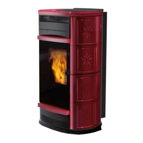
  • Seite 96: Abmessungen Un Finishes

    ABMESSUNGEN UN FINISHES - FANTASY: Spec steinver leidung. - FATA: erami cremewei , rot, ledereffe t. - SIRENA: erami cremewei , rot, ledereffe t. analisierung - STORY: grau lac ierter Stahl. armluft SE E F R IE MO ELLE G LTIGE ABMESSUNGEN...
  • Seite 97 MER MALE ELE TROAPPARATE ist ein Sicherheits- und Regelsystem der erbrennung, das unter jeder edingung einen ® optimalen etrieb gew hrleistet dan zweier Sensoren, die den ruc pegel in der erbrennungs am- mer und die Rauchgastemperatur messen, einen optimalen etrieb. essung und die daraus folgende ptimierung der beiden arameter erfolgt st ndig, sodass even- tuelle etriebsst rungen in Echtzeit behoben werden nnen.
  • Seite 98 MER MALE RMETECHNISCHE MER MALE ge äß EN 1 ennw rmeleistung ir ungsgrad ennw rmeleistung Emissionen ) ennw rmeleistung bgasmasse ennw rmeleistung Reduzierte Leistung ir ungsgrad Reduzierte Leistung Emissionen ) Reduzierte Leistung bgasmasse Reduzierte Leistung öchste bertemperatur Rauchgase indestzug etriebsdauer ( in Stun-den rennstoffverbrauch ellets ( in Fassungsvermögen des rennstoffbeh lters...
  • Seite 99 MONTAGE ER ER LEI UNGEN FATA SIRENA MITGELIEFERTE LEINTEILE: Schrauben Schrauben Sili on- bstandshalter f r die ufsatzplatte aus erami ache nterlegscheiben mit urchmesser uchsen bstandsst c e aus Sili on f r erami teile efestigungspl ttchen erami teile MONTAGE ER SEITLICHEN ACHELN (Abb. 1-2) ie R c wand ( ) abbauen und die beiden ro le (7 ).
  • Seite 100 MONTAGE ER ER LEI UNGEN FATA SIRENA MONTAGE ES ERAMI AUFSATZES FATA SIRENA (Abb. 1 ) erami - bstandshalter (*) in die entsprechenden vier freien ffnungen des usseisen- berteils stec en und die erami - blage ( ) aufsetzen Falls erforderlich, zwischen dem bstandshalter aus Sili on und dem usseisenaufsatz eine nterlegscheibe legen.
  • Seite 101 INSTALLATION RAUCHABZUG Bei Installation und Gebrauch des Geräts müssen alle loka- as Rauchabzugssyste uss f r einzig f r den Ofen len und nationalen Gesetzesvorschriften und Europanormen bestehen (Einleitung in it anderen Feuerstellen ge einsa- beachtet werden. In Italien gilt UNI 10683/2012 sowie alle Schornstein ist nicht zulässig).
  • Seite 102 INSTALLATION ARMLUFTZIR ULATION ie bgabe von armluft in den nstallationsraum erfolgt durch das im oberen eil frontal eingebaute itter ( bb. E). m die armluft in einen oder zwei benachbarte R ume zu leiten, ist der fen mit zwei Stutzen auf der R c seite versehen ( bb.
  • Seite 103 INSTALLATION 1. L SUNG: IT 11 (Art.-Nr. 6 ) - NUR BENACHBARTER RAUM NB: IE SCHL UCHE M SSEN OR ER ANBRINGUNG ER ER LEI UNG UN NACH EM AUSBAU ES OBEREN SEITENTEILS AUS GUSSEISEN AUF IE ARMLUFTAUSLASSSTUTZEN GESTEC T ER EN.
  • Seite 104 INSTALLATION 2. L SUNG: IT 11 (Art.-Nr. 6 1 ) - NUR NICHT BENACHBARTER NB: IE SCHL UCHE M SSEN OR ER ANBRINGUNG ER ER LEI UNG UN NACH EM AUSBAU ES OBEREN SEITENTEILS AUS GUSSEISEN AUF IE ARMLUFTAUSLASSSTUTZEN GESTEC T ER EN.
  • Seite 105 INSTALLATION . L SUNG: IT 11 (Art.-Nr. 6 ) und IT 11 BIS (Art.-Nr. 6 1 ) - BEI E R UME NB: IE SCHL UCHE M SSEN OR ER ANBRINGUNG ER ER LEI UNG UN NACH EM AUSBAU ES OBEREN SEITENTEILS AUS GUSSEISEN AUF IE ARMLUFTAUSLASSSTUTZEN GESTEC T ER EN.
  • Seite 106: Gebrauchsan Eisungen

    GEBRAUCHSAN EISUNGEN Die Inbetriebnahme ist einem autorisierten Servicecenter von Edilkamin zu übertragen. Die erste Einschaltung und die Abnahme hat nach UNI 10683/2012. Diese Norm bezeichnet die vor Ort vorzunehmenden Kon- trolltätigkeiten, die den ordnungsgemäßen Betrieb des Systems bestätigen sollen. Vor dem Anzünden Beim ersten Zünden ist das zuständige Servicecenter von...
  • Seite 107 GEBRAUCHSAN EISUNGEN BE IENFEL Se . lang gedr c t, schaltet ein und aus ach urzem ruc schaltet der fen von andbetrieb auf utomati betrieb um; h lt man die aste hingegen etwas l nger gedr c t ( ), hat man ugang zu den diversen rogrammiermen s. Zur Erhöhung der unterschiedlichen Einstellungen Zur erminderung der unterschiedlichen Einstellungen ei jedem ruc informiert der Speicher der Leiterplatte den ediener, dass...
  • Seite 108 GEBRAUCHSAN EISUNGEN Auto atischer Betrieb ittels Bedienfeld Fernbedienung - . t gl. rogramm (ein Ein- und ein bschalten am ag), et tigt man die aste hingegen al, schaltet man .t gl. rogramm (ebenso), . t gl. rogramm (ebenso) von andbetrieb auf utomati betrieb um und regelt die ie aste benutzen, um in umge ehrter Reihenfolge emperatur, die man im Raum erreichen möchte (zum Regeln...
  • Seite 109 Hierbei handelt es sich um Richtwerte. Größere Präzision wird - ei vom hermostaten (offener onta t) erreichter erreicht, wenn vor jedem neuen Befüllen regelmäßig auf null Raumtemperatur stellt sich der fen auf Stand-by. gesetzt wird. Edilkamin haftet in keiner Weise für Abweichun- abhängen). emperatur emperatur von...
  • Seite 110 GEBRAUCHSAN EISUNGEN FERNBE IENUNG Art.-Nr. 6 Legende der Tasten und des isplays: : Ein- bzw. usschalttaste : aste zur Erhöhung der Leistung bzw. etriebstemperatur (im nneren eines en s erhöht sie die angezeigte er nderliche) : aste zur erringerung der Leistung bzw. etriebstemperatur (im nneren eines en s verringert sie die angezeigte er nderliche) : aste, um zur rogrammierung “E S ER zu wechseln...
  • Seite 111 GEBRAUCHSAN EISUNGEN GEBRAUCH ES PROGRAMMS EASY TIMER ber die Fernbedienung ann die hrzeit besonders intuitiv und schnell programmiert werden: - Ist der Ofen eingeschaltet: Es ist möglich, ein bschalten mit einer zwischen einer und zwölf Stunden regelbaren Einstellung vorzunehmen. uf dem isplay des edienfeldes wird die bis zur programmierten bschaltung verbliebene Zeit angezeigt. - Ist der Ofen ausgeschaltet: Es ist möglich, ein Einschalten mit einer zwischen einer und zwölf Stunden regelbaren Einstellung vorzunehmen.
  • Seite 112 ARTUNG Antes de reali or der ornah e eglicher artungsarbeiten den Ofen von der Netzversorgung trennen. Eine regel äßige artung ist f r den guten Betrieb des Ofens grundlegend. IE zu indest AHRESZEITLICHE MANGELN E ARTUNG ann schlechten Betrieb verursachen. Eventuelle durch die angelnde artung verursachte Proble e bewir en den erfall der Garantie.
  • Seite 113 ARTUNG AHRESZEITLICHE ARTUNG (SEITENS ES H N LERS) esteht in: llgemeine nnen- und u enreinigung Sorgf ltige Reinigung und Ent rusten des iegels und des iegelraums Reinigung der entilatoren. echanische ontrolle des Spiels und der efestigungen Reinigung des Rauch anals ( ustausch der ichtung des Rauchabzugrohrs) Reinigung des Raums des Rauchabzugventilators Reinigung des Raums des Flusssensors Reinigung des Raums ontrolle des hermoelements...
  • Seite 114 MÖGLICHE PROBLEME Fall von St rungen hält der Ofen auto atisch an inde er den Abstellvorgang ausf hrt und auf de isplay wird der Grund f r die St rung angezeigt (siehe Meldungen weiter unten). ährend der Phase wegen Ausfalls nie als den Netzstec er ziehen. F r den Fall des erfolgten Ausfalls ist f r den erneute Start des Ofen erforderlich dass die Abschaltprozedur (6 Se unden...
  • Seite 115 MÖGLICHE PROBLEME 6 ) Anzeige: FBdefe t Fun st : (greift ein, wenn das hermoelement ausgefallen oder nicht angeschlossen ist). St rung: Abschalten wegen ausgefallene oder nicht angeschlossene Ther oele ent Maßnah en: ellettyp berpr fen, Störung Rauchabzugsmotor berpr fen en Rauch anal auf mögliche erstopfungen berpr fen ie ordnungsgem e nstallation berpr fen, as eventuelle “...
  • Seite 116: Auf Unsch Erh Ltliches Zubehör

    CHEC LISTE Mit de vollständigen Lesen der technischen Beschreibung zu ergänzen Einbau und Inbetriebnah e Inbetriebnahme durch ein zugelassenes Servicecenter, das die Garantie ausgestellt hat el ftung des Raums er Rauch anal bzw. Schornstein empf ngt nur den bzug des fens er Rauchabzug weist auf: höchstens urven höchstens...
  • Seite 117 Italiaanse norm UNI 10683/2012 bestaat uit een reeks controles nadat de kachel geïnstalleerd is van de wetgeving vaststellen. - aan de bovenkant van de verpakking CONFORMITEITSVERKLARING KACHEL MET PELLET met het commerciële merk EDILKAMIN, genaamd FANTASY - FATA - SIRENA - STORY - 117 - 117...
  • Seite 118 FUNCTIONERINGSPRINCIPE EILIGHEI SINFORMATIE e achel is ontworpen voor het verwarmen van de installatie- e achels verwarmen lucht met behulp van houtpellets, e ruimte door middel van de automatische verbranding van pel- verbranding hiervan wordt op ele tronische wijze aangestuurd. lets in de vuurhaard aan de hand van uitstraling en de beweging ieronder wordt de functionering beschreven ( e letters van de lucht die aan de voor ant naar buiten stroomt.
  • Seite 119 AFMETINGEN EN UITRUSTINGEN - FANTASY: spe steen - FATA: eramie crème leuring, rood, leder leuring. - SIRENA: eramie crème leuring, rood, leder leuring. analisatie warme - STORY: grijs geverfd staal. lucht AFMETINGEN GEL IG OOR E MO ELLEN - 119...
  • Seite 120 EIGENSCHAPPEN ELE TRONISCHE APPARATEN ® is een systeem dat de verbranding beschermt en regelt en een optimale functionering in el e omstandigheid waarborgt. an zij de twee sensoren die het dru niveau in de verbrandings a- mer en de roo temperatuur opmeten. et opmeten en de optimalisering van de twee parameters vindt continu plaats zodat eventuele storingen in de functionering onmiddellij gecorrigeerd unnen worden.
  • Seite 121 EIGENSCHAPPEN TECHNISCHE EIGENSCHAPPEN rachtens EN 1 ominaal vermogen Rendement nominaal vermogen tstoot ) nominaal vermogen ewicht roo nominaal vermogen eper t vermogen Rendement beper t vermogen tstoot ) beper t vermogen ewicht roo beper t vermogen a imum overtemperatuur roo inimum tre utonomie min ma erbrui brandstof min ma...
  • Seite 122 MONTAGE BE LE ING FATA SIRENA BI GESLOTEN MATERIAAL: schroeven schroeven verbindingsstu en in silicone voor de bovenste eramische elementen ringen moffen afstandsblo jes in silicone voor eramie eramische atieplaatjes E ZI TEGELS MONTEREN (Afb. 1-2) emonteer het paneel aan de achter ant ( ) en de twee pro elen (7 .) e beide plaatjes ( 9) vastma en aan de verzin te zij anten.
  • Seite 123 MONTAGE BE LE ING FATA SIRENA E ERAMIE EN TOP MONTEREN FATA SIRENA (Afb. 1 ) laats de afstandsblo jes voor eramie (*) in de respec- tieve openingen van de gietijzeren top en leg de eramische top ) erop breng, indien noodza elij , tussen het siliconen afstan- dsblo je en de gietijzeren top een ring aan.
  • Seite 124 INSTALLATIE ROO AF OER Tijdens de installatie en het gebruik van het apparaat moeten Het afvoersystee ag uitsluitend door de achel gebrui t de plaatselijke en nationale wetten en de Europese normen in worden (het is niet toegestaan dat de schoorsteen tevens acht worden genomen.
  • Seite 125 INSTALLATIE CIRCULATIE AN ARME LUCHT e warme lucht wordt naar de installatieruimte gezonden door het rooster dat op de voor ant bovenaan geïnstalleerd is (afb. E). e achel is voorzien van twee openingen op de achter ant (afb. ) waar u speciale aluminium buizen op aan moet sluiten om de warme lucht naar een of twee aangrenzende ruimten te analiseren.
  • Seite 126 INSTALLATIE 1 OPLOSSING: IT 11 (code 6 ) - EEN EN ELE AANGRENZEN E RUIMTE N.B.: E LEI INGEN AANGESLOTEN OP E OPENINGEN OOR E AF OER AN ARME LUCHT MOETEN AANGESLOTEN OR EN AL ORENS U E BE LE ING MONTEERT. EMONTEER OOR EZE HAN E- LING HET BO ENSTE GIETI ZEREN ZI PANEEL.
  • Seite 127 INSTALLATIE 2 OPLOSSING: IT 11 BIS (code 6 1 ) - EEN EN ELE NIET-AANGRENZEN E RUIMTE N.B.: E LEI INGEN AANGESLOTEN OP E OPENINGEN OOR E AF OER AN ARME LUCHT MOETEN AANGESLOTEN OR EN AL ORENS U E BE LE ING MONTEERT. EMONTEER OOR EZE HAN E- LING HET BO ENSTE GIETI ZEREN ZI PANEEL.
  • Seite 128 INSTALLATIE OPLOSSING: IT 11 (code 6 et IT 11 BIS (code 6 1 ) - BEI E RUIMTES N.B.: E LEI INGEN AANGESLOTEN OP E OPENINGEN OOR E AF OER AN ARME LUCHT MOETEN AANGESLOTEN OR EN AL ORENS U E BE LE ING MONTEERT. EMONTEER OOR EZE HAN E- LING HET BO ENSTE GIETI ZEREN ZI PANEEL.
  • Seite 129 Gebruiksaanwijzingen Voor het eerste opstarten is het noodzakelijk zich te wenden tot de technische bijstandsdients Edilkamin van uw zone, (voor in- formatie verwijzen we naar de site www.edilkamin.com) die de kachel zal ijken op basis van het gebruikte soort pellets en naargelang de installatievoorwaarden die de garantie activeren.
  • Seite 130 GEBRAUCHSAN EISUNGEN SYNOPTISCH PANEEL scha elt het apparaat in en uit als u hem indru t Een orte dru scha elt de achel om van handmatige naar automatische wer ing, terwijl het ingedru t houden (gedurende ) toegang verschaft tot de verschillende programmeermenu s. voor de toename van de verschillende instellingen voor de afname van de verschillende instellingen ij el e dru informeert het geheugen van de ele tronische aart dat...
  • Seite 131 GEBRAUCHSAN EISUNGEN Auto atische functionering op het synoptische paneel de et behulp van “ aily program. geldt het ingestelde program- afstandsbediening ma de ingestelde programma s voor alle dagen van de wee . oor de -toets tweemaal in te dru en scha elt men om oor vervolgens te dru en op de toets is het mogelij van handmatige wer ing naar automatische wer ing, de tempera-...
  • Seite 132 - anneer de omgevingstemperatuur wordt berei t (geopend Een grotere nauwkeurigheid wordt bekomen via een een reset contact), scha elt de achel over op stand-by. voor het herladen. Edilkamin is niet aansprakelijk voor variaties van het voorno- emperatuur emde (kan afhankelijk zijn van externe factoren). emperatuur...
  • Seite 133 GEBRAUCHSAN EISUNGEN AFSTAN SBE IENING code 6 Legenda toetsen en dispaly: : toets ontste ing uitdoving : toets om het vermogen de bedrijfstemperatuur toe te laten nemen (in een menu neemt de weergegeven variabele toe) : toets om het vermogen de bedrijfstemperatuur af te laten nemen (in een menu neemt de weergegeven variabele af) : toets waarmee u op de “E S ER programmering overscha elt M : toets waarmee u van automatisch naar handmatig en omge eerd overscha elt...
  • Seite 134 GEBRAUCHSAN EISUNGEN HET PROGRAMMA EASY TIMER GEBRUI EN et behulp van de afstandsbediening unt u een intuïtieve en snelle uurprogrammering gebrui en: - Als de achel aan staat: u unt een uitdoving instellen na één tot twaalf uur; op het display van het synoptische paneel wordt de resterende tijd tot de geprogrammeerde uitdoving weergegeven.
  • Seite 135 ON ERHOU oppel het apparaat van de ele trische voeding los voordat u een wille eurige onderhoudswer zaa heid uitvoert. Regel atig onderhoud vor t de basis een goede functionering van uw achel. HETNALATEN AN OPZI N MINST E SEIZOENSGEBON EN REINIGING an een slechte functionering veroorza- en.
  • Seite 136 ON ERHOU SEIZOENSGEBON EN ON ERHOU (door uw ealer) estaat uit: lgehele reiniging van de binnen- en buiten ant gedeelte van de voorkant van de kachel. Zorgvuldige reiniging en verwijdering van de afzettingen in de vuurhaard en de desbetreffende ruimte Reiniging van de ventilatoren, mechanische controle van de spelingen en de bevestigingen Reiniging roo anaal (vervanging van de pa ing op de roo afvoerleiding) Reiniging roo anaal (zie we elij se reiniging)
  • Seite 137 MOGELI E STORINGEN IIn dit geval o t de achel auto atisch tot stilstand en voert de uitdooffase uit. Op het display wordt een bericht et de reden voor het uitdoven weergegeven (zie hieronder de diverse signaleringen). Haal tijdens het uitdoven wegens een blo ering de ste er nooit uit het stopcontact.
  • Seite 138 MOGELI E STORINGEN 6 ) Signalering: Fault RC: (ingreep bij defect of ont oppeld thermo oppel) Storing: Uitdoving door defect of ont oppeld ther o oppel Handelingen: ontroleer het soort pellets, ontroleer of de motor roo verwijderaar storingen vertoont ontroleer of het roo anaal verstopt is ontroleer de correcte installatie, ontroleer de eventuele “drift van de reductiemotor ontroleer of in de ruimte een luchttoevoer aanwezig is...
  • Seite 139 CHEC LIST Te integreren et een co plete bestudering van het technische blad Plaatsing en installatie e inbedrijfstelling door een er ende ealer die het garantiebewijs. entilatie van de installatieruimte. et roo anaal de schoorsteen worden uitsluitend voor de achel gebrui t. et roo anaal heeft: ma imaal bochten en is ma imaal meter lang horizontaal.
  • Seite 140 - 140...
  • Seite 141 - 141...
  • Seite 142 - 142...
  • Seite 143 - 143...
  • Seite 144 w w w . e d i l a m i n . c o m cod. 9 - 144...

Diese Anleitung auch für:

FataSirenaStory

Inhaltsverzeichnis