Vimar 01471 Bedienungsanleitung
01471
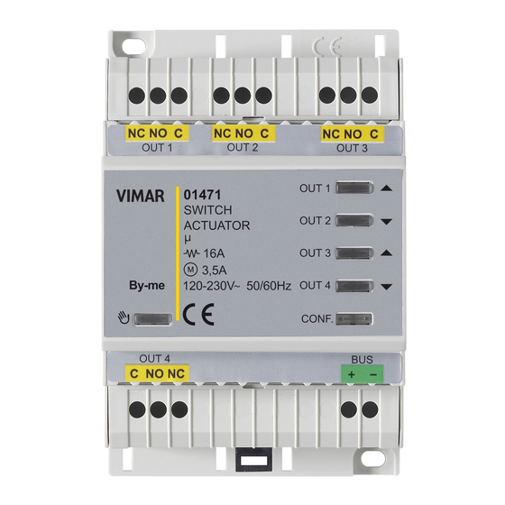
Attuatore con 4 uscite a relè in scambio 16 A 120-230 V~, program-
mabili con funzione comando luci, tapparelle con orientamento delle
lamelle, fan-coil, pulsanti per comando locale, domotica By-me,
installazione su guida DIN (60715 TH35), occupa 4 moduli da 17,5
mm.
CARATTERISTICHE.
• Tensione nominale di alimentazione: BUS 29 V.
• Assorbimento tipico: 20 mA.
• 4 uscite a relé (NC, C, NO) per il comando luci; i relè 1+2 e 3+4 sono raggruppabili
per comando tapparella.
• Utilizzabile per la funzione fan-coil.
• Pulsanti per il comando manuale dei relè.
• Pulsante per abilitare/disabilitare i comandi manuali.
• LED per lo stato dei relè.
• LED e pulsante di configurazione.
• Grado di protezione: IP20.
• Temperatura di funzionamento: -5 °C ÷ +45°C (uso interno).
• Ingombro: 4 moduli da 17,5mm.
• Compatibile con centrali By-me 21509 ed EasyTool Professional.
CARICHI COMANDABILI.
• Uscita a relè (carichi comandabili a 120 - 230 V~, contatti NO):
- carichi resistivi
: 16 A (20.000 cicli);
- lampade a incandescenza
- lampade fluorescenti, a risparmio energetico e a LED
- trasformatori elettronici
• Uscita a relè (carichi comandabili a 120 - 230 V~, contatti NO e NC):
- motori cos ø 0,6: 3,5 A (100.000 cicli).
GESTIONE MANUALE.
La pressione del tasto
abilita l'uso dei tasti per l'attuazione dei relè; tutti i mes-
saggi provenienti dal bus vengono ignorati.
• Se il dispositivo è resettato ogni relè viene comandato attraverso il proprio tasto.
• Se il dispositivo è configurato, i relè configurati singolarmente vengono coman-
dati attraverso il rispettivo tasto mentre i relè configurati a coppie per il comando
tapparella sono comandati dai tasti per la funzione di UP () e DOWN () con
tempo di inversione nel passaggio da UP a DOWN; se invece sono configurati per
la gestione fancoil i relè 1,2,3 vengono comandati in alternativa.
In funzionamento normale la pressione dei tasti di attuazione dei relè viene ignorata.
CONFIGURAZIONE CON CENTRALE BY-ME O EASYTOOL
PROFESSIONAL.
Per tutti i dettagli si vedano i relativi manuali installatore scaricabili dal sito
www.vimar.com
REGOLE DI INSTALLAZIONE.
• L'installazione deve essere effettuata con l'osservanza delle disposizioni regolan-
ti l'installazione del materiale elettrico in vigore nel paese dove i prodotti sono
installati.
• Le 4 uscite a relè sono separate tra loro mediante un isolamento funzionale a 250
V~ e non da un doppio isolamento; a fronte di ciò, ad esempio, non collegare
un circuito SELV ad un'uscita che sia adiacente ad un'altra connessa alla rete di
alimentazione a 230 V~.
• I circuiti di alimentazione delle uscite a relè devono essere protetti contro le
sovracorrenti da dispositivi o fusibili con potere di interruzione nominale di 1500 A
oppure interruttori automatici tipo C, con correnti nominali non superiori a 16 A.
CONFORMITÀ NORMATIVA.
Direttiva BT.
Direttiva EMC.
Norme EN 60669-2-5, EN 50491.
Viale Vicenza, 14 - 36063 Marostica VI - Italy
Tel. +39 0424 488 600 - Fax (Italia) +39 0424 488 188
Fax (Export) +39 0424 488 709
www.vimar.com
: 8 A (20.000 cicli);
: 0,5 A (20.000 cicli);
: 6 A (20.000 cicli);
Actuator with 4 change-over relay outputs 16 A 120-230 V~,
programmable with control function for lights, roller shutters with
slat orientation, fan-coil, push-buttons for local control, By-me home
automation system, installation on DIN rails (60715 TH35), occupies
4 modules size 17.5 mm.
FEATURES.
• Rated supply voltage: BUS 29 V.
• Typical current draw: 20 mA.
• 4 relay outputs (N/C, C, N/O) for lights control; relays 1+2 and 3+4 can be
grouped for roller shutter control.
• Can be used for the fan-coil function.
• Push-buttons for manual relay control.
• Push-button to enable/disable the manual controls.
• LED for relay status.
• LED and configuration button.
• Protection class: IP20.
• Operating temperature: -5 °C to +45°C (indoor use).
• Overall dimensions: 4 modules of 17.5mm.
• Compatible with By-me 21509 control units and EasyTool Professional.
CONTROLLABLE LOADS.
• Relay output (controllable loads at 120 - 230 V~, N/O contacts):
- resistive loads
: 16 A (20,000 cycles);
- incandescent lamps
: 8 A (20,000 cycles);
- fluorescent lamps, with energy saving and LED
- electronic transformers
• Relay output (controllable loads at 120 - 230 V~, N/O and N/C contacts):
- cos ø 0.6 motors: 3.5 A (100,000 cycles).
MANUAL MANAGEMENT.
Pressing the
button enables using the buttons to actuate the relays. All
messages from the bus are ignored.
• If the device is reset each relay is controlled with its own button.
• If the device is configured, the relays configured individually are controlled by the
relevant button while the relays configured in pairs for roller shutter control are
controlled by the buttons for the UP function () and DOWN function () with a
reversal time in the passage from UP to DOWN; whereas if they are configured for
fan-coil control, relays 1,2,3 are controlled alternately.
In normal operation, pressing the relay actuation buttons is ignored.
CONFIGURATION WITH BY-ME CONTROL UNIT OR EASYTOOL
PROFESSIONAL.
For full details see the relevant Installer manuals that can be downloaded from
the website www.vimar.com
INSTALLATION RULES.
• Installation should be carried out in compliance with the current regulations
regarding the installation of electrical systems in the country where the products
are installed.
• The 4 relay outputs are separated from each other by functional insulation at 250
V~ and not by double insulation; because of this, for example, do not connect a
SELV circuit to an output that is adjacent to another one that is connected to the
230 V~ power supply.
• The relay output power circuits must be protected against overcurrents by
installing devices or fuses with a rated breaking capacity of 1500 A or type-C
circuit breakers, with rated current not exceeding 16 A.
STANDARD CONFORMITY.
LV directive.
EMC directive.
Standards EN 60669-2-5, EN 50491.
: 0.5 A (20,000 cycles);
: 6 A (20,000 cycles);
49400826A0 02 1602
VIMAR - Marostica - Italy

Verwandte Anleitungen für Vimar 01471


Inhaltszusammenfassung für Vimar 01471
- Seite 1 Standards EN 60669-2-5, EN 50491. Viale Vicenza, 14 - 36063 Marostica VI - Italy Tel. +39 0424 488 600 - Fax (Italia) +39 0424 488 188 Fax (Export) +39 0424 488 709 49400826A0 02 1602 www.vimar.com VIMAR - Marostica - Italy...
- Seite 2 PROFESSIONAL. PROFESSIONAL. Para más detalles, consulte los correspondientes manuales del instalador que Pour les détails, consulter les manuels installateur correspondants en les se pueden descargar de la página www.vimar.com téléchargeant sur le site www.vimar.com NORMAS DE INSTALACIÓN. RÈGLES D'INSTALLATION. • La instalación debe realizarse cumpliendo con las disposiciones en vigor que •...
- Seite 3 ΔΙΑΜΟΡΦΩΣΗ ΜΕ ΚΕΝΤΡΙΚΗ ΜΟΝΑΔΑ BY-ME Η EASYTOOL Für alle Details wird auf die entsprechenden Installationsanleitungen PROFESSIONAL. verwiesen, die zum Download auf der Website www.vimar.com verfügbar sind Για όλες τις λεπτομέρειες, ανατρέξτε στα σχετικά εγχειρίδια τεχνικού εγκατάστασης που είναι διαθέσιμα για λήψη από την ιστοσελίδα www.
- Seite 4 OUT 4 C NO NC Viale Vicenza, 14 - 36063 Marostica VI - Italy Tel. +39 0424 488 600 - Fax (Italia) +39 0424 488 188 Fax (Export) +39 0424 488 709 49400826A0 02 1602 www.vimar.com VIMAR - Marostica - Italy...