System Sensor IM-10 Installations- Und Wartungsanleitung
Verfügbare Sprachen
Verfügbare Sprachen
Quicklinks
INSTALLATION AND MAINTENANCE INSTRUCTIONS
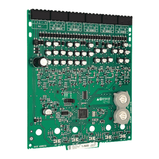
IM-10
Ten Input Monitor Module
SPECIFICATIONS
Normal Operating Voltage:
Stand-By Current:
Alarm Current:
Temperature Range:
Humidity:
Dimensions:
Accessories:
Wire Gauge:
Maximum SLC Wiring Resistance:
Maximum IDC Wiring Resistance:
Maximum IDC Voltage:
Maximum IDC Current:
BEFORE INSTALLING
This information is included as a quick reference installation guide. Refer to
the appropriate control panel installation manual for detailed system infor-
mation. If the modules will be installed in an existing operational system,
inform the operator and local authority that the system will be temporarily
out of service. Disconnect the power to the control panel before installing the
modules. This system contains static sensitive components. Always ground
yourself with a proper wrist strap before handling any circuits so that static
charges are removed from the body. The housing cabinet should be metallic
and suitably grounded.
NOTICE: This manual should be left with the owner/user of this equipment.
GENERAL DESCRIPTION
The IM-10 Ten Input Monitor Module is intended for use in an intelligent
alarm system. Each monitor module is intended to interface between a control
panel and normally open contact devices, such as pull stations. A common
SLC input is used for all modules, and the initiating device loops share a
common supervisory supply and ground. Otherwise, each monitor operates
independently from the others. Each module has its own unique address.
A pair of rotary code switches is used to set the address of the first module
from 01 to 90. The remaining modules are automatically assigned to the next
nine higher addresses. Provisions are included for disabling a maximum of
two unused modules to release the addresses to be used elsewhere. Each
module also has panel controlled green LED indicators. The panel can cause
the LEDs to blink, latch on, or latch off.
Included:
(6) 1 x 4 Terminal Blocks
(4) Screws
(3) Shunts
Shipped on Board:
(1) Shunt
COMPATIBILITY REQUIREMENTS
To ensure proper operation, this module shall be connected to a listed com-
patible system control panel.
The IM-10 Module shall be mounted in a suitably grounded Metallic Cabinet
for EMC compliance.
D500-66-00
15-32 VDC
3.5 mA
60 mA (assumes all ten LEDs solid on)
–10°C to 55°C
10 to 93% Non condensing
17.3cm H x 14.7cm W x 3.2cm D
Suitably grounded metallic cabinet
0.9mm 2 - 3.25mm 2
40 Ohms
40 Ohms
12 VDC
1 mA
(2) 3.2 cm Stand offs
(2) Nuts
(10) 47k Ohm
End of Line Resistors
WIRING
NOTE:
All wiring must conform to applicable local codes,
ordinances, and regulations.
1.
Install module wiring in accordance with the job drawings and appropri-
ate wiring diagrams.
2.
All wiring to the IM-10 is done via terminal blocks. In order to properly
make electrical connections strip approximately .6 cm of insulation from
the end of wire, sliding the bare end of the wire under the clamping plate
screw.
3.
Set the address on the modules per the job drawing. Use the rotary code
switches to set the address of the first module (between 01 and 90).
The remaining modules are automatically assigned to the next nine higher
addresses. For example, if the base address switch is set to 28, the next nine
modules will be addressed to 29, 30, 31, 32, 33, 34, 35, 36, and 37.
DO NOT set the lowest address above 90, as the other modules will be as-
signed to nonexistent addresses.
4.
A shunt is provided to disable a maximum of two unused modules.
Modules are disabled from the highest address and work downward. If
two modules are disabled, the lowest eight addresses will be functional,
while the highest two will be disabled. For example, if the shunt for
Address Disable is placed on "two" and the base switch is set to 28, the
modules will be assigned to 28, 29, 30, 31, 32, 33, 34 and 35 while dis-
abling the highest two positions.
NOTE:Place unused shunts on single pin to store on board for future use.
1
Pittway Technologica S.p.A
Via Caboto 19/3
34147 Trieste, Italy
I56-2254-003

Verwandte Anleitungen für System Sensor IM-10


Inhaltszusammenfassung für System Sensor IM-10
-
Seite 7: Spezifikation
Brandmelderzentrale angeschlossen werden. ieren Sie die zuständigen Personen und die regionalen Behörden, dass ggfs. Das IM-10-Modul sollte für die Erfüllung der EMV-Richtlinie in einem die Anlage zeitweise außer Betrieb genommen wird. Schalten Sie die Zentrale geeigneten, geerdeten Metallgehäuse montiert werden vor dem Beginn der Installationsarbeiten spannungsfrei. - Seite 8 SIGNALKABEL 32 VDC MAX. VERDRILLTE ADERN ERFORDERLICH C0302-00 HINWEIS: Der gemeinsame Betrieb von Alarmgebern und Überwachungbau- gruppen auf einer Meldelinie ist nicht zulässig. Installieren Sie die Schließerkontakte gemäß den Herstelleranweisungen. 0832-CPD-0927 EN54-18: 2005 INPUT/OUTPUT DEvICE D500-66-00 I56-2254-003 © 2009 System Sensor...