System Sensor M210EA-CZ Installationsanleitung
Verfügbare Sprachen
Verfügbare Sprachen
Quicklinks
Fig./Abb. 1
1:2 DIN
1:1 M200E-SMB
Sollevare
Levantar
Anheben
Fig./Abb. 2
Fig./Abb. 3
Honeywell Building Technologies, Building 5 Carlton Park, King Edward Avenue, Narborough, Leicester LE19 3EQ
D200-504-00
60°C
-20°C
2
1
Rotate
Plug
Ruotare
Inserire
Girar
Conectar
Drehen
Einhaken
Clip / Agganciare
3
Acoplar / Einrasten
3
1
Lift
Push down
Premere
Precionar
hacia abajo
Runterdrücken
Rotate / Ruotare
2
Girar / Drehen
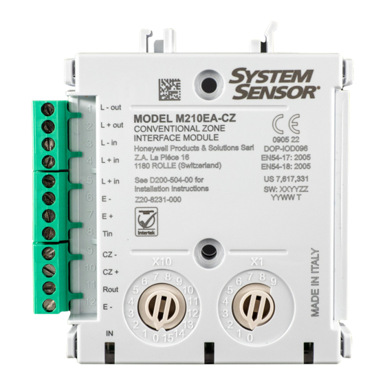
M210EA-CZ
0905 22
DOP-IOD096
EN 54-17: 2005, EN 54-18: 2005
Honeywell Products and Solutions Sàrl
(Trading as System Sensor Europe)
Zone d'activités La Pièce 16
CH-1180 ROLLE, Switzerland
M210EA-CZ
EN
CONVENTIONAL ZONE INTERFACE MODULE
This manual is intended as a quick reference installation guide. Please refer to the
control panel manufacturers installation manual for detailed system information.
The M200 series of modules are a family of microprocessor controlled interface
devices permitting the monitoring and/or control of auxiliary devices.The M210EA-CZ
M210EA-CZ
provides an interface between a zone of System Sensor manufactured conventional
type fire detection devices and an intelligent signalling loop.
A single tri-colour LED indicates the status of the module. In normal conditions, the
LED can be set by command from the control panel to blink green when the module
is polled. In the case of a fire alarm on the conventional zone, the LED is switched
on constant red by panel command. If a fault is detected on the conventional zone or
M200E-SMB
the zone supply voltage drops below 18 V, or a fault with the external power supply
is signalled, the LED will blink yellow if enabled on the control panel. When a short
circuit is detected on the loop to either side of the module, the LED is switched to show
a constant yellow light.
This module does not require maintenance.
SPECIFICATIONS
Intelligent Loop
Operating Voltage Range: see S00-7100
LED Cutoff Voltage: 16.5 V
Max. Standby Current (@24 V and 25
No Communication:
Max. Standby Current (@24 V and 25
EOL only, Loop Powered Conventional Zone:
No Communication:
LED Current (Red):
LED Current (Yellow):
Isolator Features: see S00-7100
Conventional Zone
Supply Voltage:
Maximum Standby Load Current: 3 mA for detectors
Maximum Zone Load:
Maximum Conventional Line Resistance: 50 Ω (both legs)
End of Line Capacitor:
General
Humidity:
Ingress protection:
Maximum Wire Gauge:
INSTALLATION
Note: These modules must only be connected to control panels using System Sensor
proprietary analogue addressable communication protocols for monitoring and control.
M200 series modules can be mounted in several ways (See Figure 1):
1:1 An M200E-SMB custom low profile surface-mounting box. The SMB Base is
affixed to mounting surface, and then the module and cover are screwed onto
the base using the two screws supplied. Box dimensions: 132 mm (H) x 137 mm
(W) x 40 mm (D)
1:2 The DIN bracket on top allows mounting onto standard 35 mm x 7.5 mm "Top Hat"
DIN rail inside a control panel or other suitable enclosure. Install and remove as
shown in Figure 1:2
Wiring to all series M200 modules is via plug in type terminals capable of supporting
conductors up to 2.5 mm²
Disconnect loop power before installing modules or sensors.
The module address is selected by means of rotary decade address switches (see
Figure 3). A screwdriver should be used to rotate the wheels to select the desired
address, either from the front or the top of the module.
Note: The number of addresses available will be dependent on panel capability,
check the panel documentation for information on this.
Short Circuit Isolators
All M200 series modules are provided with short circuit monitoring and isolators on the
intelligent loop. If required the isolators may be wired out of the loop to facilitate the
use of the modules on high current loaded loops, for example if sounders are used.
To achieve this, the loop out positive should be wired to terminal 5 rather than terminal
2. See Figure 2 for details.
INSTALLATION INSTRUCTIONS - M210EA-CZ
C) External Supply Conventional Zone:
o
C) Conventional Zone connected to Capacitive
o
1.3 mA
4.5 mA
18 to 32 V (either from loop or external supply)
17.5 mA (limited internally)
47 μF non-polarised. M200E-EOL-C supplied
5% to 95% relative humidity (non-condensing)
IP44 (mounted in M200E-SMB)
2.5 mm²
CAUTION
CAUTION
Electrostatic Sensitive Device
Observe precautions when handling and making connections
120 µA
1.3 mA
I56-4412-000

Verwandte Anleitungen für System Sensor M210EA-CZ


Inhaltszusammenfassung für System Sensor M210EA-CZ
- Seite 4 M210EA-CZ Anschaltung Das Modul M210EA-CZ kann so angeschaltet werden, dass die Standardmeldergruppe INSTALLATIONSANLEITUNG FÜR M210EA-CZ von einem externen Netzteil oder, vorausgesetzt der Strombedarf kann gedeckt INTERFACE-MODUL FÜR werden, direkt von der Ringleitung versorgt werden kann. Beim Einsatz einer externen STANDARDMELDERGRUPPEN Spannungsversorgung ist die Standardmeldergruppe vollständig von der Ringleitung...