System Sensor M201EA-240 Installationsanleitung
Steuermodule für netzschaltspannung
Verfügbare Sprachen
Verfügbare Sprachen
Fig./Abb. 1
1:2 DIN
1:1 M200E-SMB
Sollevare
Levantar
Anheben
Fig./Abb. 2
Fig./Abb. 3
Note:
In order to meet the requirements of European Safety Standards, ensure
that all cables carrying voltages in excess of 48V are suitably fused.
DOP-IOD073
EN54-17: 2005
EN54-18: 2005
0786
0786
22
D200-502-00
Honeywell Building Technologies, Building 5 Carlton Park, King Edward Avenue, Narborough, Leicester LE19 3EQ
INSTALLATION INSTRUCTIONS FOR MAINS
SWITCHING OUTPUT MODULE
60°C
-20°C
2
1
Rotate
Plug
Ruotare
Inserire
Girar
Conectar
Drehen
Einhaken
Clip / Agganciare
3
Acoplar / Einrasten
3
1
Lift
Push down
Premere
Precionar
hacia abajo
Runterdrücken
Rotate / Ruotare
2
Girar / Drehen
M201EA-240
Honeywell Products and Solutions Sàrl
(Trading as System Sensor Europe)
Zone d'activités La Pièce 16
CH-1180 ROLLE, Switzerland
M201EA-240
This manual is intended as a quick reference installation guide. Please
refer to the control panel manufacturers installation manual for detailed
system information.
The installation must be carried out by expert personnel, that is, a person
with education or experience to identify hazards and take appropriate
actions to reduce the risk of injury to themselves and others.
GENERAL INFORMATION
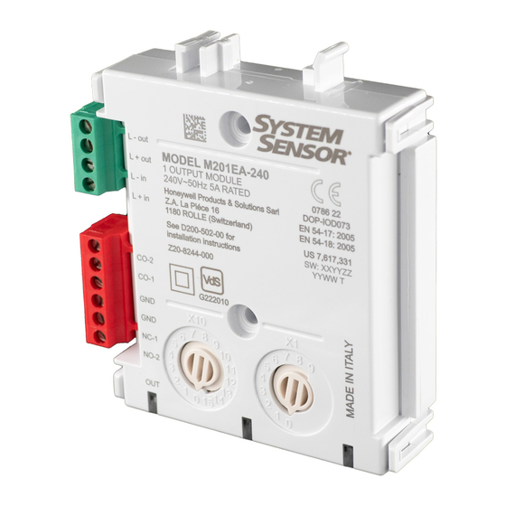
M201EA-240
The M200 series of modules are a family of microprocessor controlled
interface devices permitting the monitoring and/or control of auxiliary
devices. The M201EA-240 is an output module, providing 250VAC 5A
rated voltage free contacts, both normally open and normally closed.
SPECIFICATIONS
M200E-SMB
Operating Voltage Range:
LED Cutoff Voltage:
Maximum Standby Current (µA): 75µA - No Communication
Fault Current:
Coil Activation/Deactivation Current: 76mA Maximum for 12ms
Relay Contact Rating:
Isolator Features:
Operating Temperature:
Humidity:
Maximum Wire Gauge
Disconnect loop power before installing modules or sensors.
High voltages may be present on terminals 7 to 12.
INSTALLATION
Note: This module must only be connected to control panels using
compatible proprietary analogue addressable communication protocols for
monitoring and control.
M200 series modules can be mounted in several ways (See Figure 1):
1:1 An M200E-SMB custom low profile surface-mounting box. The SMB
Base is affixed to mounting surface, and then the module and cover
are screwed onto the base using the two screws supplied. Box
dimensions: 132 mm (H) x 137 mm (W) x 40 mm (D)
1:2 The DIN bracket on top allows mounting onto standard 35 mm x 7.5
mm "Top Hat" DIN rail inside a control panel or other suitable enclosure.
Install and remove as shown in Figure 1:2.
Wiring to all series M200 modules is via plug in type terminals capable
of supporting conductors up to 2.5 mm²
Ensure that the correct terminals are used for the loop and
switched voltage as damage may result from incorrect usage.
The module address is selected by means of rotary decade address
switches (see figure 3), accessed at the front of the module. A screwdriver
should be used to rotate the wheels to select the desired address. (Note:
The number of addresses available will be dependent on panel capability,
check the panel documentation for information on this).
Short Circuit Isolators
All M200 series modules are provided with short circuit monitoring and
isolators on the intelligent loop. If required the isolators may be wired
out of the loop to facilitate the use of the modules on high current loaded
loops, for example if sounders are used. To achieve this, the loop out
positive should be wired to terminal 4 rather than terminal 2.
E N G L I S H
see S00-7100
16.5 VDC
5.5 mA (Yellow LED illuminated)
5A at 30VDC, 5A at 250VAC
see S00-7100
-20°C to 60°C
5% to 95% Relative Humidity
2.5 mm²
CAUTION
WARNING
I56-4410-000

Verwandte Anleitungen für System Sensor M201EA-240


Inhaltszusammenfassung für System Sensor M201EA-240
- Seite 4 -20°C Die Module der Serie M200 sind Mikroprozessor gesteuerte Elemente die die Überwachung und/oder Steuerung von externen Baugruppen ermöglicht. Die Module der Serie M201EA-240 verfügen über potentialfreie Ausgänge, mit wahlweiser Schließer/Öffner Funktionalität, über die eine Netzwechselspannung von 250VAC/5A geschaltet werden M200E-SMB kann.