System Sensor M211E-RF Installationsanweisungen
Inhaltsverzeichnis
Verfügbare Sprachen
Verfügbare Sprachen
Quicklinks
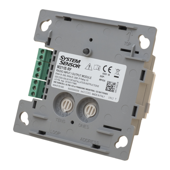
PARTS LIST
Module unit
SMB500 back box
Front cover
Batteries (Duracell Ultra 123 or Panasonic Industrial 123)
Back box fixing screws and wall plugs
Module fixing screws
3-pin terminal block
2-pin terminal block
47 k-ohm EOL resistor
18 k-ohm alarm resistor
Module installation instructions
SMB500 back box installation instructions
+
251 g
(66 g)
Figure 1: IO module + back box outside dimensions
125 mm
Figure 2: Diode Polarity
Load -VE
D200-309-00
RADIO SYSTEM INPUT / OUTPUT MODULE
INSTALLATION INSTRUCTIONS
=
317 g
58
mm
125
mm
Table 1: Terminal Connections
CONNECTION / FUNCTION
TERMINAL
Input Module
Input -ve
1
Input +ve
2
Output module (Supervised mode)
3
Connect to T8
4
To load +ve
5
Connect to T7
6
Supervision: connect to load -ve
7
To ext PSU –ve
8
To ext PSU +ve
Load +VE
Pittway Tecnologica S.r.l. Via Caboto 19/3, 34147 TRIESTE, Italy
M211E-RF
DESCRIPTION
1
The M211E-RF radio input-output module is a battery operated RF
1
device designed for use with the M200G-RF radio gateway, running
1
on an addressable fire system (using a compatible proprietary
4
communication protocol).
2
It is a dual module having separate input and output capability,
2
combined with a wireless RF transceiver and is supplied with a
2
wireless back box.
1
This device conforms to EN54-18 and EN54-25. It complies with the
2
requirements of 2014/53/EU for conformance with the RED directive.
1
SPECIFICATIONS
1
1
Supply Voltage:
Standby Current:
Red LED Current Max: 2 mA
Green LED Cur. Max:
60°C
Re-Sync Time:
-20°C
Batteries:
Battery Life:
Radio Frequency:
RF Output Power:
Range:
Relative Humidity:
Terminal Wire Size:
IP Rating:
Input Module
End-of-Line Resistor:
Supervision Current:
Output Module
End-of-Line Resistor:
Supervision Current:
Relay Contacts:
External Power Supply Unit
Voltage:
Supervision Fault Voltage: 7V DC typical
INSTALLATION
This equipment and any associated work must be installed in
accordance with all relevant codes and regulations.
Figure 1 details the dimensions of the back box and cover.
Spacing between radio system devices must be a minimum of 1m
Table 1 shows the wiring configuration of the module.
Output module (Relay mode)
Relay NO (normally open)
Relay C (common)
Relay NC (normally closed)
Not used
Not used
Not used
Input Module requires 47K EOL for normal operation.
Output Module requires 47K EOL at the load for normal
operation in supervised mode.
If the load is a low impedance (compared to the EOL) a
series diode should be added for correct load supervision
(see Figure 2 for diode polarity).
I 56- 4267- 002
3.3 V Direct Current max.
122 µA@ 3V (typical in normal operating mode)
5.5 mA
35s (max time to normal RF communication from
device power on)
4 X Duracell Ultra123 or Panasonic Industrial 123
4 years @ 25
C
o
865-870 MHz. Channel width: 250kHz
14dBm (max)
500m (typ. in free air)
5% to 95% (non-condensing)
0.5 - 2.5 mm
2
IP20
47K
34 µA typical
47K
60 µA typical
2 A @ 30 VDC (resistive load)
30V DC max. 8V DC min.
E N G L I S H
I56-4267-002
Inhaltsverzeichnis

Verwandte Anleitungen für System Sensor M211E-RF


Inhaltszusammenfassung für System Sensor M211E-RF
-
Seite 10: Spezifikationen
D E U T S C H M211E-RF RADIOSYSTEM-EINGANGS- / AUSGANGSMODUL INSTALLATIONSANWEISUNGEN TEILLISTE BESCHREIBUNG Moduleinheit Beim M211E-RF handelt sich Radio-Eingangs- Ausgangsmodul, das mit Batterien betrieben wird und für die SMB500-Back-Box Verwendung mit einem M200G-RF Radio-Gateway entwickelt wurde. Vordere Abdeckung Es läuft auf einem adressierbaren Feuersystem (durch die Verwendung Batterien (Duracell Ultra 123 oder Panasonic Industrial 123) 4 eines kompatiblen proprietären Kommunikationsprotokolls). -
Seite 11: Einstellung Der Adresse
WARNUNG: Wechsel von induktiven Ladungen Abb. 3: Wechsel von induktiven Ladungen Siehe Abb. 3 Induktive Lasten können Überspannungen verursachen und die Modulrelaiskontakte beschädigen (i). Um die Relaiskontakte zu schützen, schließen Sie über der Last einen geeigneten Überspannungsschutz an (iii) - z. B. 1N6284CA - über die Ladung (ii) wie gezeigt in Abb. -
Seite 12: Programmierung Und Kommissionierung
¨ ¨ Honeywell Products and Solutions Sàrl Inbetriebnahme (Trading as System Sensor Europe) 1) Entfernen Sie das Modul aus der Back Box. Zone d’activités La Pièce 16 CH-1180 ROLLE, Switzerland 2) Stellen Sie sicher, dass die richtige Adresse auf dem Gerät EN54-25: 2008 / AC: 2010 / AC: 2012 eingestellt ist.