System Sensor M201EA Installationsanleitung
Verfügbare Sprachen
Verfügbare Sprachen
Quicklinks
Fig./Abb. 1
1:1 M200E-SMB
Fig./Abb. 2
Fig./Abb. 3
Fig./Abb. 4
DOP-IODxxx
0905
EN54-17: 2005
20
EN54-18: 2005
D200-501-00
M201EA
22 mm
60°C
-20°C
1:2 DIN
M201EA
M201EA
(i)
+
(iii)
(ii)
Honeywell Products and Solutions Sàrl
(Trading as System Sensor Europe)
Zone d'activités La Pièce 16
CH-1180 ROLLE, Switzerland
Pittway Tecnologica S.r.l, Via Caboto 19/3, 34147 Trieste, Italy
EN
INSTALLATION INSTRUCTIONS
FOR THE M201EA OUTPUT MODULE
This manual is intended as a quick reference installation guide. Please refer to the
control panel manufacturers installation manual for detailed system information.
The M200 series of modules are a family of microprocessor controlled interface
devices permitting the monitoring and/or control of auxiliary devices. The M201EA
is an output module that allows the control of auxiliary devices such as fire shutters
or sounders.
A single tri-colour LED indicates the status of the module. In normal conditions, the
LED can be set by command from the control panel to blink green when the module is
polled. When the control panel switches the relay to the energised state the LED can
be set to continuous green.
SPECIFICATIONS
Operating Voltage Range:
15 to 32VDC (Min 16.5VDC for LED operation)
Maximum Standby Current
160µA - No Communication
LED Current (Red):
1.5mA
LED Current (Yellow):
5.5mA
Isolator features:
see S00-7100-xxx
Humidity:
5% to 95% relative humidity (non-condensing)
Maximum Wire Gauge
2.5mm²
INSTALLATION
Note: These modules must only be connected to control panels using compatible
proprietary analogue addressable communication protocols for monitoring and control.
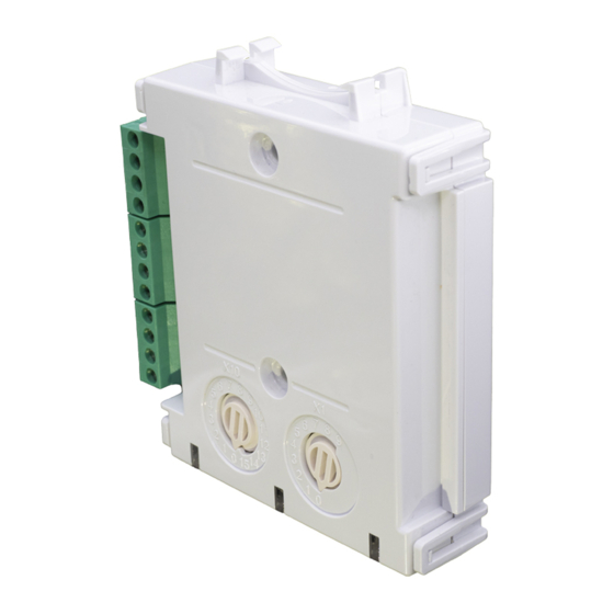
M200 series modules can be mounted in several ways (See Figure 1):
1:1 An M200E-SMB custom low profile surface-mounting box. The SMB Base is
affixed to mounting surface, and then the module and cover are screwed onto
the base using the two screws supplied. Box dimensions: 132mm(H) x 137mm(W)
x 40mm(D)
1:2 The DIN bracket on top allows mounting onto standard 35mm x 7.5mm "Top Hat"
DIN rail inside a control panel or other suitable enclosure. Push module into adaptor
bracket until it clips into place. Locate top clip over DIN rail and rotate bottom down
to clip into place. To remove, lift up, then rotate top away from the rail.
Wiring to all series M200 modules is via plug in type terminals capable of supporting
conductors up to 2.5mm²
Disconnect loop power before installing modules or sensors.
The module address is selected by means of rotary decade address switches (see
Figure 4). A screwdriver should be used to rotate the wheels to select the desired
address, either from the front or the top of the module. (Note: The number of addresses
available will be dependent on panel capability, check the panel documentation for
information on this.)
Short Circuit Isolators
All M200 series modules are provided with short circuit monitoring and isolators on the
intelligent loop. If required the isolators may be wired out of the loop to facilitate the
use of the modules on high current loaded loops, for example if sounders are used.
To achieve this, the loop out positive should be wired to terminal 5 rather than terminal
2. See the relevant wiring diagram for details.
M201EA WIRING
The M201EA can be wired for either Supervised (Figure 2) or Non-Supervised
(Figure 3) operation respectively.
Electrostatic Sensitive Device
Observe precautions when handling and making connections
M201EA Single Output Module with Supervised Output
When the module is used in supervised mode and power is supplied to the module,
a switched negative input on terminal 12 can be used to signal an external fault
condition, such as a power supply fault. Loss of power is also supervised in this mode
such that if the supply voltage falls below 7V a fault indication is achievable. Note that
the use of this fault mode is dependant on panel software. Please contact the panel
manufacturer for further details.
PSU monitoring is not available when the module switches the output to Alarm.
Wire as follows (see Figure 2):
a: T1 Loop Output -. b: T2 Loop Output +. c: T3 Loop Input -. d: T4 Loop Input +
e: T5 Loop Output +. If short circuit isolation is not required, loop output+ should be
wired to terminal 5 and not 2. Terminal 5 is internally connected to terminal 4.
f: To enable output circuit supervision, the link supplied must be fitted across
terminals 6 and 7,and the load must be polarised.
CAUTION
CAUTION
I56-4401-000
DRAFT

Verwandte Anleitungen für System Sensor M201EA


Inhaltszusammenfassung für System Sensor M201EA
- Seite 4 Ausgang "Ringleitung+" direkt an Klemme 5 und nicht an Klemme 2 angeschlossen werden. M201EA Verdrahtung Das Modul M201EA kann für den überwachten (Abbildung 2) oder nicht überwachten (Abbildung 3) Betrieb verdrahtet werden. ACHTUNG Elektrostatisch empfindliches Gerat Beachten Sie die Vorschriften fur den Umgang mit elektrostatisch empfindlichen Geraten M201EA Steuermodul mit Einem Überwachbarem Ausgang...