Herunterladen Inhalt Inhalt Diese Seite drucken

Werbung

Verfügbare Sprachen
  • DE

Verfügbare Sprachen

  • DEUTSCH, seite 39
Version 1.0
Published May 2014
Copyright©2014 ASRock INC. All rights reserved.
Copyright Notice:
No part of this documentation may be reproduced, transcribed, transmitted, or
translated in any language, in any form or by any means, except duplication of
documentation by the purchaser for backup purpose, without written consent of
ASRock Inc.
Products and corporate names appearing in this documentation may or may not
be registered trademarks or copyrights of their respective companies, and are used
only for identification or explanation and to the owners' benefit, without intent to
infringe.
Disclaimer:
Specifications and information contained in this documentation are furnished for
informational use only and subject to change without notice, and should not be
constructed as a commitment by ASRock. ASRock assumes no responsibility for
any errors or omissions that may appear in this documentation.
With respect to the contents of this documentation, ASRock does not provide
warranty of any kind, either expressed or implied, including but not limited to
the implied warranties or conditions of merchantability or fitness for a particular
purpose.
In no event shall ASRock, its directors, officers, employees, or agents be liable for
any indirect, special, incidental, or consequential damages (including damages for
loss of profits, loss of business, loss of data, interruption of business and the like),
even if ASRock has been advised of the possibility of such damages arising from any
defect or error in the documentation or product.
This device complies with Part 15 of the FCC Rules. Operation is subject to the following
two conditions:
(1) this device may not cause harmful interference, and
(2) this device must accept any interference received, including interference that
may cause undesired operation.
CALIFORNIA, USA ONLY
The Lithium battery adopted on this motherboard contains Perchlorate, a toxic substance
controlled in Perchlorate Best Management Practices (BMP) regulations passed by the
California Legislature. When you discard the Lithium battery in California, USA, please
follow the related regulations in advance.
"Perchlorate Material-special handling may apply, see www.dtsc.ca.gov/hazardouswaste/
perchlorate"
ASRock Website: http://www.asrock.com

Werbung

Inhaltsverzeichnis
loading

Inhaltszusammenfassung für ASROCK Z97 OC Formula

  • Seite 1 (including damages for loss of profits, loss of business, loss of data, interruption of business and the like), even if ASRock has been advised of the possibility of such damages arising from any defect or error in the documentation or product.
  • Seite 2 The terms HDMI™ and HDMI High-Definition Multimedia Interface, and the HDMI logo are trademarks or registered trademarks of HDMI Licensing LLC in the United States and other countries. Manufactured under license under U.S. Patent Nos: 5,956,674; 5,974,380; 6,487,535; 7,003,467 & other U.S. and worldwide patents issued & pending. DTS, the Symbol, & DTS and the Symbol together is a registered trademark &...
  • Seite 3: Motherboard-Layout

    Z97 OC Formula Motherboard Layout CPU_FAN2 ATX12V1 CPU_FAN1 HDMI1 ATX12V3 USB 3.0 T: USB0 B: USB1 USB 3.0 T: USB2 B: USB3 USB 2.0 T: USB2 B: USB3 USB 3.0 Top: T: USB4 RJ-45 B: USB5 USB3_6_7 CHA_FAN4 CHA_FAN3 PCIE1...
  • Seite 4 No. Description ATX 12V Power Connector (ATX12V3) ATX 12V Power Connector (ATX12V1) CPU Fan Connector (CPU_FAN1) CPU Fan Connector (CPU_FAN2) 2 x 240-pin DDR3 DIMM Slots (DDR3_A1, DDR3_B1) 2 x 240-pin DDR3 DIMM Slots (DDR3_A2, DDR3_B2) V-Probe (VOL_CON1, VOL_CON2) ATX Power Connector (ATXPWR1) USB 3.0 Header (USB3_6_7) SATA3 Connector (SATA3_A1) SATA3 Connector (SATA3_A2)
  • Seite 5 Z97 OC Formula No. Description Thunderbolt AIC Connector (TB1) USB 2.0 Header (USB4_5) Power Fan Connector (PWR_FAN1) Chassis Fan Connector (CHA_FAN1) TPM Header (TPMS1) COM Port Header (COM1) PCIe Power Connector (PCIE_PWR1) Front Panel Audio Header (HD_AUDIO1) Clear CMOS Jumper (CLRMOS1)
  • Seite 6 1.4 I/O Panel No. Description No. Description USB 2.0 Ports (USB01) Rear Speaker (Black) HDMI Port Line In (Light Blue) USB 3.0 Ports (USB3_01) Front Speaker (Lime)** Clear CMOS Switch (CLRCBTN1) Microphone (Pink) USB 3.0 Ports (USB3_23) Optical SPDIF Out Port USB 2.0 Ports (USB23) USB 3.0 Ports (USB3_45) LAN RJ-45 Port*...
  • Seite 7 Z97 OC Formula * There are two LEDs on each LAN port. Please refer to the table below for the LAN port LED indications. ACT/LINK LED SPEED LED LAN Port Activity / Link LED Speed LED Status Description Status Description...
  • Seite 8: Package Contents

    If you require technical support related to this mother- board, please visit our website for specific information about the model you are using. You may find the latest VGA cards and CPU support list on ASRock’s website as well. ASRock website http://www.asrock.com.
  • Seite 9 Core™ i7/i5/i3/Pentium®/Celeron® Processors (Socket 1150) • Digi Power design • 12 Power Phase design • Supports Intel® Turbo Boost 2.0 Technology • Supports Intel® K-Series unlocked CPUs • Supports ASRock BCLK Full-range Overclocking • Intel® Z97 Chipset • Dual Channel DDR3 Memory Technology Memory • 4 x DDR3 DIMM Slots...
  • Seite 10 • 7.1 CH HD Audio with Content Protection (Realtek ALC1150 Audio Audio Codec) • Premium Blu-ray Audio support • Supports Surge Protection (ASRock Full Spike Protection) • Supports Purity Sound - Nichicon Fine Gold Series Audio Caps - 115dB SNR DAC with Differential Amplifier - TI®...
  • Seite 11 AHCI, Hot Plug and ASRock HDD Saver Technology • 2 x SATA3 6.0 Gb/s Connectors by ASMedia ASM1061, sup- port NCQ, AHCI, Hot Plug and ASRock HDD Saver Technol- • 1 x SATA Express Connector (shared with SATA3_4, SATA3_5 and M.2 Socket) * Support to be announced • 1 x M.2_SSD (NGFF) Socket 3, supports M.2 SATA3 6.0 Gb/s...
  • Seite 12 • 1 x Thunderbolt AIC Connector • 1 x USB 2.0 Header (Supports 2 USB 2.0 ports) (Supports ESD Protection (ASRock Full Spike Protection)) • 1 x USB 3.0 Header (Supports 2 USB 3.0 ports) (Supports ESD Protection (ASRock Full Spike Protection)) • 1 x Power Switch with LED...
  • Seite 13 Due to limitation, the actual memory size may be less than 4GB for the reservation for sys- tem usage under Windows® 32-bit operating systems. Windows® 64-bit operating systems do not have such limitations. You can use ASRock XFast RAM to utilize the memory that Windows® cannot use.
  • Seite 14 Chapter 2 Installation This is an ATX form factor motherboard. Before you install the motherboard, study the configuration of your chassis to ensure that the motherboard fits into it. Pre-installation Precautions Take note of the following precautions before you install motherboard components or change any motherboard settings.
  • Seite 15: Installing The Cpu

    Z97 OC Formula 2.1 Installing the CPU 1. Before you insert the 1150-Pin CPU into the socket, please check if the PnP cap is on the socket, if the CPU surface is unclean, or if there are any bent pins in the socket. Do not force to insert the CPU into the socket if above situation is found.
  • Seite 17 Z97 OC Formula Please save and replace the cover if the processor is removed. The cover must be placed if you wish to return the motherboard for after service.
  • Seite 18 2.2 Installing the CPU Fan and Heatsink...
  • Seite 19 Z97 OC Formula 2.3 Installing Memory Modules (DIMM) This motherboard provides four 240-pin DDR3 (Double Data Rate 3) DIMM slots, and supports Dual Channel Memory Technology. 1. For dual channel configuration, you always need to install identical (the same brand, speed, size and chip-type) DDR3 DIMM pairs.
  • Seite 21 Z97 OC Formula 2.4 Expansion Slots (PCI Express Slots) There are 6 PCI Express slots on the motherboard. Before installing an expansion card, please make sure that the power supply is switched off or the power cord is unplugged. Please read the documentation of the expansion card and make necessary hardware settings for the card before you start the installation.
  • Seite 22 2.5 Jumpers Setup The illustration shows how jumpers are setup. When the jumper cap is placed on the pins, the jumper is “Short”. If no jumper cap is placed on the pins, the jumper is “Open”. The illustration shows a 3-pin jumper whose pin1 and pin2 are “Short” when a jumper cap is placed on these 2 pins.
  • Seite 23 Z97 OC Formula 2.6 Onboard Headers and Connectors Onboard headers and connectors are NOT jumpers. Do NOT place jumper caps over these headers and connectors. Placing jumper caps over the headers and connectors will cause permanent damage to the motherboard.
  • Seite 24 Power LED Header Please connect the chassis (3-pin PLED1) power LED to this header PLED- PLED+ (see p.1, No. 26) to indicate the system’s PLED+ power status. Serial ATA3 Connectors These eight SATA3 (SATA3_0) connectors support SATA (see p.1, No. 12) data cables for internal (SATA3_1) storage devices with up to...
  • Seite 25 Z97 OC Formula USB_PWR USB 2.0 Header Besides four USB 2.0 (9-pin USB4_5) ports on the I/O panel, DUMMY (see p.1, No. 35) there is one header on this motherboard. Each USB 2.0 header can support two ports. USB_PWR Vbus Vbus USB 3.0 Header...
  • Seite 26 Chassis Speaker Header Please connect the chassis DUMMY SPEAKER (4-pin SPEAKER1) speaker to this header. DUMMY (see p.1, No. 22) GN D Chassis and Power Fan Please connect fan cables FAN_VOLTAGE CHA_FAN_SPEED Connectors to the fan connectors and FAN_SPEED_CONTROL (4-pin CHA_FAN1) match the black wire to (see p.1, No.
  • Seite 27 Z97 OC Formula ATX 12V Power This motherboard pro- Connectors vides two 8-pin ATX 12V (8-pin ATX12V1) power connectors. To use (see p.1, No. 2) a 4-pin ATX power sup- (8-pin ATX12V3) ply, please plug it along (see p.1, No. 1) Pin 1 and Pin 5.
  • Seite 28 TPM Header This connector supports (17-pin TPMS1) Trusted Platform Module (see p.1, No. 38) (TPM) system, which cansecurely store keys, digital certificates, passwords, and data. A TPM system also helps enhance network security, protects digital identities, and ensures platform integrity.
  • Seite 29 Z97 OC Formula V-Probe Users are able to measure onboard components IGPU (7-pin VOL_ voltage. CON1, 7-pin VOL_ Cache CON2) IOD: VCORE0 (see p.1, No. 7) CPU digital IO voltage IGPU: GT voltage 1.5PCH 1.05PCH CPU system agent voltage VDimm...
  • Seite 30: Smart Switches

    2.7 Smart Switches The motherboard has ten smart switches: Power Switch, Reset Switch, Clear CMOS Switch, Rapid OC Buttons, Menu Button, PCIe ON/OFF Switch, Slow Mode Switch, BIOS Selection Switch and LN2 Mode Switch. Power Switch Power Switch allows users to Power (PWR) quickly turn on/off the system.
  • Seite 31 Z97 OC Formula PCIe ON/OFF PCIe ON/OFF Switch allows Switch you to enable and disable the (PCIE_SWITCH) corresponding PCIE x16 slots. 1 2 3 4 (see p.1, No. 33) When one of the installed PCIE x16 cards is out of order,...
  • Seite 32 LN2 Mode Switch The LN2 mode aids in (LN2MODE) eliminating the cold-boot bug (see p.1, No. 31) issues in processors during extreme overclocking with Liquid Nitrogen.
  • Seite 33 Z97 OC Formula 2.8 Dr. Debug Dr. Debug is used to provide code information, which makes troubleshooting even easier. Please see the diagrams below for reading the Dr. Debug codes. Code Description Please check if the CPU is installed correctly and then clear CMOS.
  • Seite 34 Problem related to USB devices. Please try removing all USB devices. Problem related to memory. Please re-install the CPU and memory then clear CMOS. If the problem still exists, please install only one memory module or try using other memory modules.
  • Seite 35 Z97 OC Formula 2.9 M.2_SSD (NGFF) Module Installation Guide The M.2, also known as the Next Generation Form Factor (NGFF), is a small size and versatile card edge connector that aims to replace mPCIe and mSATA. The M.2_SSD (NGFF) Socket 3 can accommodate either a M.2 SATA3 6.0 Gb/s module or a M.2 PCI Express module up to Gen 2 x2 (10 Gb/s).
  • Seite 36 Step 3 Move the standoff based on the module type and length. The standoff is placed at the nut location D by default. Skip Step 3 and 4 and go straight to Step 5 if you are going to use the default nut. Otherwise, release the standoff by hand.
  • Seite 37 Z97 OC Formula M.2_SSD (NGFF) Module Support List PCIe Interface SATA Interface Plextor PX-G512M6e ADATA AXNS381E-128GM-B Plextor PX-G256M6e ADATA AXNS381E-256GM-B SanDisk SD6PP4M-128G Crucial CT120M500SSD4/120G SanDisk SD6PP4M-256G Crucial CT240M500SSD4/240G Samsung XP941-512G (MZHPU512HCGL) Intel SSDSCKGW080A401/80G Kingston RBU-SM2280S3/120G For the latest updates of M.2_SSD (NFGG) module support list, please visit our website...
  • Seite 38: Connection Diagram

    2.10 HDD Saver Cable Installation Guide The HDD Saver Connector on this motherboard allows you to switch on and off the connected HDDs via software when needed. This design secures more privacy, saves more energy, and extends the HDDs' lifespans. Please follow the steps below to install the HDD Saver Cable.
  • Seite 39: Einleitung

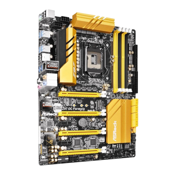
    Z97 OC Formula 1 Einleitung Vielen Dank für den Kauf unseres ASRock Z97 OC Formula, eines zuverlässigen Motherboards, das nach ASRocks strengen Qualitätsrichtlinien gefertigt wurde. Es liefert ausgezeichnete Leistung mit robustem Design, das ASRocks Streben nach Qualität und Beständigkeit erfüllt.
  • Seite 40: Technische Daten

    Prozessoren (Sockel 1150) der 5., 4. und neuen 4. Generation • Digipower-Design • 12-Leistungsphasendesign • Unterstützt Intel® Turbo Boost 2.0-Technologie • Unterstützt CPUs mit freiem Multiplikator der Intel® K-Serie • Unterstützt ASRock BCLK-Übertaktung (voller Bereich) • Intel® Z97 Chipsatz • Dualkanal-DDR3-Speichertechnologie Speicher • 4 x DDR3-DIMM-Steckplätze...
  • Seite 41 HDMI-Port • 7.1-Kanal-HD-Audio mit Inhaltsschutz (Realtek ALC1150- Audio Audiocodec) • Erstklassige Blu-ray-Audiounterstützung • Unterstützt Überspannungsschutz (ASRock Full Spike Protec- tion) • Unterstützt Purity Sound - Nichicon-Audiokappen der Fine Gold-Serie - 115-dB-SRV-DAC mit Differentialverstärker - TI® NE5532 – erstklassiger Headset-Verstärker (unterstützt...
  • Seite 42 RAID (RAID 0, RAID 1, RAID 5, RAID 10, Intel Rapid Storage Technology 13 und Intel Smart Response Technology), NCQ, AHCI, Hot-Plugging und ASRock HDD-Saver-Technologie • 2 x SATA-III-6,0-Gb/s-Anschlüsse von ASMedia ASM1061, unterstützt NCQ, AHCI, Hot-Plugging und ASRock HDD- Saver-Technologie • 1 SATA Express-Anschluss (geteilt mit SATA3_4, SATA3_5 und M.2-Sockel) * Anzukündigende Unterstützung...
  • Seite 43: Anschluss

    • 1 x Audioanschluss an Frontblende • 1 x Thunderbolt-Erweiterungskartenanschluss • 1 x USB 2.0-Stiftleiste (unterstützt 2 USB 2.0-Ports) (unterstützt Schutz gegen elektrostatische Entladung (ASRock- Rundumschutz vor Spannungsspitzen)) • 1 x USB 3.0-Stiftleiste (unterstützt 2 USB 3.0-Ports) (unterstützt Schutz gegen elektrostatische Entladung (ASRock- Rundumschutz vor Spannungsspitzen)) • 1 x Ein-/Austaste mit LED...
  • Seite 44 Aufgrund von Beschränkungen kann die Größe des tatsächlich für die Systemnutzung reser- vierten Speichers unter Windows®-Betriebssystemen mit 32 Bit weniger als 4 GB betragen. Windows®-Betriebssysteme mit 64 Bit haben keine derartigen Beschränkungen. Mit ASRock XFast RAM können Sie den Speicher einsetzen, den Windows® nicht nutzen kann.
  • Seite 45: Jumpereinstellung

    Z97 OC Formula 1.3 Jumpereinstellung Die Abbildung zeigt, wie die Jumper eingestellt werden. Wenn die Jumper-Kappe auf den Kontakten angebracht ist, ist der Jumper „kurzgeschlossen“. Wenn keine Jumper- Kappe auf den Kontakten angebracht ist, ist der Jumper „offen“. Die Abbildung zeigt einen 3-poligen Jumper, dessen Kontakt 1 und Kontakt 2 „kurzgeschlossen“...
  • Seite 46: Integrierte Stiftleisten Und Anschlüsse

    1.4 Integrierte Stiftleisten und Anschlüsse Integrierte Stiftleisten und Anschlüsse sind KEINE Jumper. Bringen Sie KEINE Jumper-Kappen an diesen Stiftleisten und Anschlüssen an. Durch Anbringen von Jumper-Kappen an diesen Stiftleisten und Anschlüssen können Sie das Motherboard dauerhaft beschädigen. Systemblende-Stiftleiste Verbinden Sie PLED+ PLED- (9-polig, PANEL1)
  • Seite 47 Z97 OC Formula Betrieb-LED-Stiftleiste Bitte verbinden Sie die (3-polig, PLED1) Betrieb-LED des Gehäuses PLED- PLED+ (siehe S. 1, Nr. 26) zur Anzeige des System- PLED+ betriebsstatus mit dieser Stiftleiste. Serial-ATA3-Anschlüsse Diese acht SATA-III- (SATA3_0) Anschlüsse unterstützen (siehe S. 1, Nr. 12) SATA-Datenkabel für...
  • Seite 48 USB_PWR USB 2.0-Stiftleiste Neben vier USB 2.0-Ports (9-polig, USB4_5) an der E/A-Blende befindet DUMMY (siehe S. 1, Nr. 35) sich eine Stiftleiste an diesem Motherboard. Jede USB 2.0-Stiftleiste kann zwei Ports unterstützen. USB_PWR Vbus Vbus USB 3.0-Stiftleiste Neben sechs USB 3.0-Ports Vbus IntA_PB_SSRX- (19-polig, USB3_6_7)
  • Seite 49 Z97 OC Formula Gehäuselautsprecher- Bitte verbinden Sie den DUMMY SPEAKER stiftleiste Gehäuselautsprecher mit DUMMY (4-polig, SPEAKER1) dieser Stiftleiste. (siehe S. 1, Nr. 22) Gehäuse- und Netzteillüfter- Bitte verbinden Sie die +12V CHA_FAN_SPEED anschlüsse Lüfterkabel mit den FAN_SPEED_CONTROL (4-polig, CHA_FAN1) Lüfteranschlüssen; der (siehe S.
  • Seite 50 ATX 12 V-Stromanschlüsse Dieses Motherboard bietet (8-polig, ATX12V1) zwei 8-polige ATX-12-V- (siehe S. 1, Nr. 2) Netzanschlüsse. Bitte (8-polig, ATX12V3) schließen Sie es zur Nut- (siehe S. 1, Nr. 1) zung eines 4-poligen ATX- Netzteils entlang Kontakt 1 und Kontakt 5 an. PCIe-Netzanschluss Bitte verbinden Sie ein 4-poliges (4-polig, PCIE_PWR1)
  • Seite 51 Z97 OC Formula TPM-Stiftleiste Dieser Anschluss (17-polig, TPMS1) unterstützt das Trusted (siehe S. 1, Nr. 38) Platform Module- (TPM) System, das Schlüssel, digitale Zertifikate, Kennwörter und Daten sicher aufbewahren kann. Ein TPM-System hilft zudem bei der Stärkung der Netzwerksicherheit, schützt digitale Identitäten und gewährleistet die...
  • Seite 52 V-Probe Benutzer können Span- nung integrierter Kompo- IGPU (VOL_CON1 nenten messen. (7-polig), VOL_ Cache CON2 (7-polig)) IOD: VCORE0 CPU-Digital-I/O-Spannung (siehe S. 1, Nr. 7) IGPU: GT-Spannung 1.5PCH 1.05PCH CPU-Systemagent-Span- VDimm nung Input Volt Cache: CPU-Cache-Spannung IOA: CPU-Analog-I/ O-Spannung VCORE0: CPU-CORE0-Spannung ICC: ICC-Spannung DMI:...
  • Seite 53 Z97 OC Formula 1.5 Intelligente Schalter Das Motherboard verfügt über zehn spezielle Tasten: Ein/Aus, Reset, CMOS löschen, Rapid OC-Tasten, Menü, PCIe-Ein/Aus, Reduzierte Geschwindigkeit, BIOS-Auswahl, LN2-Modus. Ein-/Ausschalter Mit dem Ein-/Ausschalter (PWR) kann der Benutzer das Power (siehe S. 1, Nr. 24) System schnell ein-/ abschalten.
  • Seite 54 PCIe-Ein-/ PCIe-Ein-/Ausschalter Ausschalter(PCIE_ ermöglicht Ihnen die De-/ SWITCH) Aktivierung der ent- 1 2 3 4 (siehe S. 1, Nr. 33) sprechenden PCIE-x16- Steckplätze. Wenn eine der installierten PCIE-x16- Karte nicht funktioniert, können Sie mit dem PCIe- Ein-/Ausschalter die defekte Karte mit einem einzigen Klick ausfindig machen, ohne die Karten entfernen zu müssen.
  • Seite 55 Z97 OC Formula LN2-Modusschalter Der LN2-Modus hilft (LN2MODE) bei der Eliminierung (siehe S. 1, Nr. 31) von Kaltstartfehlern in Prozessoren bei extremer Übertaktung mit flüssigem Stickstoff.
  • Seite 56: Contenu De L'emballage

    Si vous avez besoin d’une assistance technique pour votre carte mère, veuillez visiter notre site Internet pour plus de détails sur le modèle que vous utilisez. La liste la plus récente des cartes VGA et des processeurs pris en charge est également disponible sur le site Internet de ASRock. Site Internet ASRock http://www.asrock.com.
  • Seite 57 • Prend en charge la technologie Intel® Turbo Boost 2.0 • Prend en charge les processeurs débloqués de la série K Intel® • Prend en charge l’ o verclocking ASRock BCLK Full-range • Intel® Z97 Chipset • Technologie mémoire double canal DDR3 Mémoire...
  • Seite 58 Audio Realtek ALC1150) • Compatible audio Blu-ray Premium • Protection contre les surtensions (Protection complète contre les pics ASRock) • Prend en charge Purity Sound - Couvercles audio série en or fin Nichicon - 115dB SNR DAC avec amplificateur différentiel - Amplificateur de casque TI®...
  • Seite 59 Wake On sur Internet • Prend en charge la fonction Wake-On-LAN • Protection contre les orages/décharges électrostatiques (Protection complète contre les pics ASRock) • Prend en charge la fonction d’ é conomie d’ é nergie Ethernet 802.3az • Prend en charge PXE • 1 x port souris/clavier PS/2...
  • Seite 60 RAID (RAID 0, RAID 1, RAID 5, RAID 10, technologies Intel Rapid Storage 13 et Intel Smart Response), NCQ, AHCI, « Hot Plug » et sauvegarde HDD ASRock • 2 x connecteurs SATA3 6,0 Go/s ASMedia ASM1061, compatibles avec les fonctions NCQ, AHCI, « Hot Plug » et sauvegarde HDD ASRock • 1 x connecteur SATA Express (partagé...
  • Seite 61 • 1 x embase USB 2.0 (2 ports USB 2.0 pris en charge) (Protection contre les décharges électrostatiques (Protection complète contre les pics ASRock)) • 1 x embase USB 3.0 (2 ports USB 3.0 pris en charge) (Protection contre les décharges électrostatiques (Protection complète contre les pics ASRock))
  • Seite 62: Système D'exploitation

    En raison de limitations dues au système d’ e xploitation, la capacité de mémoire utilisée sous Windows® 32-bit peut être inférieure à 4 Go. Cette limitation ne concerne pas les systèmes d’ e xploitation Windows® 64-bit. Vous pouvez utiliser ASRock XFast RAM pour utiliser la mémoire dont Windows® ne peut se servir.
  • Seite 63 Z97 OC Formula 1.3 Configuration des cavaliers (jumpers) L’illustration ci-dessous vous renseigne sur la configuration des cavaliers (jumpers). Lorsque le capuchon du cavalier est installé sur les broches, le cavalier est « court- circuité ». Si le capuchon du cavalier n’ e st pas installé sur les broches, le cavalier est « ouvert ».
  • Seite 64 1.4 Embases et connecteurs de la carte mère Les embases et connecteurs situés sur la carte NE SONT PAS des cavaliers. Ne placez JAMAIS de capuchons de cavaliers sur ces embases ou connecteurs. Placer un capuchon de cavalier sur ces embases ou connecteurs endommagera irrémédiablement votre carte mère. Embase du panneau Branchez le bouton PLED+...
  • Seite 65 Z97 OC Formula Embase LED Veuillez brancher le d’alimentation LED d’alimentation PLED- PLED+ (PLED1 à 3 broches) du châssis sur cette PLED+ (voir p.1, No. 26) embase pour indiquer l’ é tat d’alimentation du système. Connecteurs Serial ATA3 Ces huit connecteurs...
  • Seite 66 USB_PWR Embases USB 2.0 En plus des quatre ports (USB4_5 à 9 broches) USB 2.0 sur le panneau DUMMY (voir p.1, No. 35) E/S, cette carte mère est dotée d’une embase supplémentaire. Chaque embase USB 2.0 peut USB_PWR prendre en charge deux ports.
  • Seite 67 Z97 OC Formula Embase du haut-parleur Veuillez brancher le DUMMY SPEAKER du châssis haut-parleur du châssis DUMMY (SPEAKER1 à 4 broches) sur cette embase. (voir p.1, No. 22) Connecteurs du châssis Veuillez brancher les +12V et de l’alimentation du câbles du ventilateur...
  • Seite 68 Connecteur Cette carte mère est d’alimentation ATX dotée d’un connecteur (ATXPWR1 à 24 d’alimentation ATX à broches) 24 broches. Pour utiliser (voir p.1, No. 8) une alimentation ATX à 20 broches, veuillez effectuer les branche- ments sur la Broche 1 et la Broche 13.
  • Seite 69 Z97 OC Formula Embase pour port série Cette embase COM1 RRXD1 DDTR#1 (COM1 à 9 broches) DDSR#1 prend en charge un CCTS#1 (voir p.1, No. 39) module de port série. RRI#1 RRTS#1 TTXD1 DDCD#1 Embase TPM Ce connecteur prend (TPMS1 à 17 broches) en charge un module (voir p.1, No.
  • Seite 70 V-Probe Les utilisateurs peuvent mesurer la tension des IGPU (VOL_CON1 7 composants embarqués. broches, VOL_ Cache CON2 7 broches) IOD : VCORE0 Tension ES numérique CPU (voir p.1, No. 7) IGPU : Tension GT 1.5PCH 1.05PCH tension agent système CPU VDimm Input Volt Cache : Tension cache CPU IOA :...
  • Seite 71 Z97 OC Formula 1.5 Boutons intelligents La carte mère est équipée de dix boutons intelligents : Bouton d’alimentation, bouton de réinitialisation, bouton effacer CMOS, boutons OC rapide, bouton menu, bouton PCIe ON/OFF, bouton mode lent, bouton sélection BIOS et bouton mode LN2.
  • Seite 72 Interrupteur marche/ L’interrupteur marche/arrêt arrêt PCIe PCIe permet à l’utilisateur (PCIE_SWITCH) d’activer et de désactiver les 1 2 3 4 (voir p.1, No. 33) fentes PCIE x16 correspondan- tes. Si l’une des 16 cartes PCIE installées est défectueuse, vous pouvez utiliser l’interrupteur marche/arrêt PCIE pour détecter cette carte défectueuse d’un seul clic sans devoir retirer...
  • Seite 73 Z97 OC Formula Interrupteur mode LN2 Le mode LN2 aide à éliminer (LN2MODE) le bogue associé au démarrage (voir p.1, No. 31) à froid des processeurs en cas d’ o verclocking extrême au nitrogène liquide.
  • Seite 74: Contenuto Della Confezione

    Web di ASRock senza ulteriore preavviso. Per il supporto tecnico correlato a questa scheda madre, visitare il nostro sito Web per informazioni specifiche relative al modello attualmente in uso.
  • Seite 75 • Design Digi Power • Potenza a 12 fasi • Supporta la tecnologia Intel® Turbo Boost 2.0 • Supporto di CPU unlocked Intel® K-Series • Supporta gamma completa overclocking BCLK ASRock • Intel® Z97 Chipset • Tecnologia con memoria DDR3 a doppio canale Memoria • 4 alloggi DIMM DDR3...
  • Seite 76 Audio Realtek ALC1150) • Supporto audio Blu-ray Premium • Supporto protezione da sovratensione (protezione completa ASRock dai picchi di corrente) • Supporto di Purity Sound - Cappucci audio Nichicon serie Fine Gold - 115dB SNR DAC con amplificatore differenziale - TI® NE5532 Premium Headset Amplifier (supporta cuffie fino...
  • Seite 77 Hot Plug e la tecnologia ASRock HDD Saver • 2 x Connettori SATA3 6,0Gb/s ASMedia ASM1061, supportano NCQ, AHCI, Hot Plug e la tecnologia ASRock HDD Saver • 1 x Connettore SATA Express (condiviso con SATA3_4, SATA3_5 e Socket M.2) * Supporto di prossima comunicazione • 1 x Socket 3 M.2_SSD (NGFF), supporta il modulo M.2 SATA3...
  • Seite 78 • 1 x Collettore USB 2.0 (supporta 2 porte USB 2.0) (supporto protezione da scariche elettrostatiche (ESD) (protezione completa ASRock dai picchi di corrente)) • 1 x Collettore USB 3.0 (supporta 2 porte USB 3.0) (supporto protezione da scariche elettrostatiche (ESD) (protezione completa ASRock dai picchi di corrente)) • 1 x interruttore d’alimentazione con LED...
  • Seite 79 Windows® a 32 bit. I sistemi operativi Win- dows® a 64 bit non possiedono tali limitazioni. È possibile utilizzare la RAM XFast di ASRock per utilizzare la memoria che Windows® non può utilizzare.
  • Seite 80 1.3 Impostazione jumper L'illustrazione mostra in che modo vengono impostati i jumper. Quando il cappuccio del jumper è posizionato sui pin, il jumper è "cortocircuitato". Se sui pin non è posizionato alcun cappuccio del jumper, il jumper è "aperto". L'illustrazione mostra un jumper a 3 pin i cui pin1 e pin2 sono "cortocircuitati"...
  • Seite 81 Z97 OC Formula 1.4 Header e connettori sulla scheda Gli header e i connettori sulla scheda NON sono jumper. NON posizionare cappucci del jumper su questi header e connettori. Il posizionamento di cappucci del jumper su header e connettori provocherà danni permanenti alla scheda madre.
  • Seite 82 Header LED di Collegare il LED di alimentazione alimentazione chassis a PLED- PLED+ (PLED1 a 3 pin) questo header per indicare PLED+ (vedere pag. 1, n. 26) lo stato di alimentazione del sistema. Connettori Serial ATA3 Questi otto connettori (SATA3_0) SATA3 supportano cavi di (vedere pag.
  • Seite 83 Z97 OC Formula USB_PWR Header USB 2.0 Oltre alle quattro porte (USB4_5 a 9 pin) USB 2.0 sul pannello I/O, DUMMY (vedere pag. 1, n. 35) su questa scheda madre vi è un header. Ciascun header USB 2.0 può supportare due porte.
  • Seite 84 Header altoparlante chas- Collegare l'altoparlante DUMMY SPEAKER dello chassis a questo DUMMY (SPEAKER1 a 4 pin) header. (vedere pag. 1, n. 22) Connettori ventola dello Collegare i cavi della +12V CHA_FAN_SPEED chassis e di alimentazione ventola ai connettori della FAN_SPEED_CONTROL (CHA_FAN1 a 4 pin) ventola e far corrispondere (vedere pag.
  • Seite 85 Z97 OC Formula Connettori di Questa scheda madre è alimentazione ATX da 12 dotata di due connettori di alimentazione ATX da (ATX12V1 a 8 pin) 12 V a 8 pin. Per utilizzare (vedere pag. 1, n. 2) un'alimentazione ATX a...
  • Seite 86 Header TPM Questo connettore (TPMS1 a 17 pin) supporta il sistema TPM (vedere pag. 1, n. 38) (Trusted Platform Module) che può archiviare in sicurezza chiavi, certificati digitali, password e dati. Un sistema TPM permette anche di potenziare la sicurezza della rete, di proteggere identità...
  • Seite 87 Z97 OC Formula V-Probe Gli utenti sono in grado di misurare la tensione dei IGPU (7-pin VOL_ componenti integrati. CON1, 7-pin VOL_ Cache CON2) IOD: VCORE0 Tensione CPU IO digitale (vedere pag. 1, n. 7) IGPU: voltaggio GT 1.5PCH 1.05PCH...
  • Seite 88 1.5 Interruttori intuitivi La scheda madre è dotata di dieci interruttori intuitivi: Interruttore di alimentazione, Interruttore di ripristino, Interruttore Clear CMOS, Pulsanti OC rapido, Pulsante menu, Interruttore ON/OFF PCle, Interruttore modalità lenta, Interruttore di selezione BIOS e Interruttore modalità LN2. Interruttore d’alimentazione L’interruttore d’alimentazione (PWR)
  • Seite 89: Interruttore On/Off

    Z97 OC Formula Interruttore ON/OFF L'interruttore ON/OFF PCIe PCIe consente di abilitare e (PCIE_SWITCH) disabilitare i 16 alloggi PCIE 1 2 3 4 (vedere pag. 1, n. 33) corrispondenti. Quando una delle 16 schede PCIE instal- late è guasta, è possibile usare...
  • Seite 90 Interruttore modalità LN2 La modalità LN2 aiuta ad (LN2MODE) eliminare i problemi di bug (vedere pag. 1, n. 31) dovuti all'accensione a freddo nei processori, durante l'overclock estremo ad azoto liquido.
  • Seite 91: Contenido Del Paquete

    Si esta documentación sufre alguna modificación, la versión actualizada estará disponible en el sitio web de ASRock sin previo aviso. Si necesita asistencia técnica relacionada con esta placa base, visite nuestro sitio web para obtener información específica sobre el modelo que esté...
  • Seite 92 • Diseño de 12 fases de alimentación • Compatible con la tecnología de Intel® Turbo Boost 2.0 • Compatible con CPU serie K desbloqueada de Intel® • Compatible con overclocking de rango completo BCLK de ASRock • Intel® Z97 Conjunto de chips • Tecnología de memoria de Doble Canal DDR3...
  • Seite 93 Z97 OC Formula • La Tecnología visual integrada de gráficos HD de Intel® y las Gráficos salidas de VGA son compatibles únicamente con procesadores con GPU integrado. • Compatible con la Tecnología visual integrada de gráficos HD de Intel®: Intel® Quick Sync Video con AVC, MVC (S3D) y MPEG-2 Full HW Encode1, Intel®...
  • Seite 94 (compatible con protección contra electricidad estática (protección ASRock Full Spike)) • 2 puertos USB 3.0 (Intel® Z97) (compatible con protección contra electricidad estática (protección ASRock Full Spike)) • 1 puerto LAN RJ-45 con LED (ACT/LINK LED y SPEED LED) • 1 interruptor de borrado CMOS • Conector de audio HD: Altavoz trasero / Central / Graves /...
  • Seite 95 Z97 OC Formula • 1 Cabezal de puerto COM Conec- • 1 cabezal TPM tores • 1 cabezal de indicador LED de alimentación • 2 Conectores de ventilador de la CPU (1 de 4 pines y 1 de 3 pines) • 4 Conectores de ventilador del chasis (1 de 4 pines y 3 de 3...
  • Seite 96 Windows® de 32 bits. Los sitemas opera- tivos Windows® de 64 bits no tienen estas limitaciones. Podrá utilizar XFast RAM de ASRock para usar la memoria que Windows® no puede utilizar.
  • Seite 97 Z97 OC Formula 1.3 Instalación de los puentes La instalación muestra cómo deben instalarse los puentes. Cuando la tapa de puente se coloca en los pines, el puente queda “Corto”. Si no coloca la tapa de puente en los pines, el puente queda “Abierto”. La ilustración muestra un puente de 3 pines cuyo pin 1 y pin 2 son “Cortos”...
  • Seite 98 1.4 Conectores y cabezales incorporados Los cabezales y conectores incorporados NO son puentes. NO coloque tapas de puente sobre estos cabezales y conectores. Si coloca tapas de puente sobre los cabezales y conectores dañará de forma permanente la placa base. Cabezal del panel del Conecte el interruptor de PLED+...
  • Seite 99 Z97 OC Formula Cabezal de indicador LED Conecte el indicador LED de alimentación de alimentación del chasis PLED- PLED+ (PLED1 de 3 pines) a este cabezal para indicar PLED+ (consulte la pág.1, N.º 26) el estado de alimentación del sistema.
  • Seite 100 USB_PWR Cabezal USB 2.0 Además de cuatro puertos (USB4_5 de 9 pines) USB 2.0 en el panel I/O, DUMMY (consulte la pág.1, N.º 35) esta placa base contiene un cabezal. Cada cabezal USB 2.0 admite dos puertos. USB_PWR Cabezal USB 3.0 Además de seis puertos Vbus Vbus...
  • Seite 101 Z97 OC Formula Cabezal de altavoces del Conecte el altavoz del DUMMY SPEAKER chasis chasis a este cabezal. DUMMY (SPEAKER1 de 4 pines) (consulte la pág.1, N.º 22) Conectores del ventilador Conecte los cables del +12V de alimentación y del...
  • Seite 102 Conectores de Esta placa base contiene alimentación ATX de 12V dos conectores de alimen- (ATX12V1 de 8 pines) tación ATX de 12V y 8 (consulte la pág.1, N.º 2) pines. Para utilizar una (ATX12V3 de 8 pines) toma de alimentación ATX (consulte la pág.1, N.º...
  • Seite 103 Z97 OC Formula Cabezal TPM Este conector es (TPMS1 de 17 pines) compatible con el sistema (consulte la pág.1, N.º 38) Módulo de Plataforma Segura (TPM, en inglés), que puede almacenar de forma segura claves, certificados digitales, contraseñas y datos. Un sistema TPM también...
  • Seite 104 V-Probe Los usuarios pueden medir el voltaje de los compo- IGPU VOL_CON1 de 7 nentes integrados. contactos, VOL_ Cache CON2 de 7 contac- IOD: VCORE0 tos) Voltaje de E/S digital de la (consulte la pág.1, N.º 7) IGPU: Voltaje GT 1.5PCH 1.05PCH VDimm...
  • Seite 105 Z97 OC Formula 1.5 Interruptores inteligentes La placa base contiene diez interruptores inteligentes: Interruptor de alimentación, Interruptor de restablecimiento, Borrar CMOS, Botones Rapid OC, Botón Menú, Interruptor de activación y desactivación de PCIe, Interruptor de modo Lento, Interruptor de selección del BIOS y Conmutador de Modo LN2.
  • Seite 106 Interruptor de activación El interruptor de encendido/ desactivación de PCIe apagado de PCIe le permite (consulte la pág.1, N.º 33) activar y desactivar las ranuras 1 2 3 4 PCIE x16 correspondientes. Cuando una de las tarje- tas PCIE x16 instaladas no funcione, puede utilizar el interruptor de encendido/apa- gado de PCIe para encontrar la...
  • Seite 107 Z97 OC Formula Interruptor del Modo LN2 El modo LN2 ayuda a (LN2MODE) eliminar los problemas de (consulte la pág.1, N.º 31) errores del arranque en frío de los procesadores durante el overclocking extremo con nitrógeno líquido.
  • Seite 108: Комплект Поставки

    уведомления. При необходимости технической поддержки, связанной с материнской платой, посетите веб-сайт и найдите на нем информацию о модели используемой вами материнской платы. На веб-сайте ASRock также можно найти самый последний перечень поддерживаемых VGA-карт и ЦП. Веб-сайт ASRock http://www.asrock.com. 1.1 Комплект поставки...
  • Seite 109 • Digi Power design • Система питания 12 • Поддержка технологии Intel® Turbo Boost 2.0 • Поддержка процессоров Intel® серии K с разблокированным множителем • Поддержка полного разгона процессора ASRock BCLK • Intel® Z97 Чипсет • Двухканальная память DDR3 Память...
  • Seite 110 • 7.1-канальный звук высокой четкости HD Audio с Аудио защитой данных (аудиокодек Realtek ALC1150) • Поддержка Premium Blu-ray Audio • Защита от перенапряжения (ASRock Full Spike Pro- tection) • Поддержка Purity Sound - Конденсаторы для аудиосистем серии Nichicon Fine Gold - 115 дБ...
  • Seite 111 • Поддержка технологии Qualcomm® Atheros® Security Wake On Internet Technology • Поддержка Wake-On-LAN • Молниезащита и защита электростатического напряжения (ASRock Full Spike Protection) • Поддержка Energy Efficient Ethernet 802.3az • Поддержка PXE • 1 x PS/2 для мыши/клавиатуры Порты ввода- • 1 x HDMI...
  • Seite 112 "горячего" подключения и ASRock HDD Saver • 2 x Разъемы SATA3 со скоростью передачи данных 6 ГБ/с с ASMedia ASM1061, поддержка технологии NCQ, AHCI, "горячее" подключение и ASRock HDD Saver • 1 x Разъем SATA Express (для использования с SATA3_4, SATA3_5 и M.2 Socket) * О...
  • Seite 113 • 1 x аудиоразъем на передней панели • 1 x AIC-разъем Thunderbolt • 1 x Колодка USB 2.0 (до 2 портов USB 2.0) с защитой от электростатического напряжения (ASRock Full Spike Protection) • 1 x Колодка USB 3.0 (до 2 портов USB 3.0) с защитой...
  • Seite 114 • Microsoft® Windows® 10 64-bit / 8.1 32-bit / 8.1 64-bit / ОС 8 32-bit / 8 64-bit / 7 32-bit / 7 64-bit • FCC, CE, WHQL Сертификация • Совместимость с ErP/EuP (необходим блок питания, соответствующий стандарту ErP/EuP) * Для получения дополнительной информации об изделии посетите наш веб-сайт: http://www.asrock.com...
  • Seite 115 вызванный разгоном процессора. В связи с ограничением при работе под 32-разрядной ОС Windows® фактический объем памяти может быть меньше 4 Гбайт. Для 64-разрядных ОС Windows® таких ограничений нет. Для использования той памяти, которую ОС Windows® не может использовать, используйте ASRock XFast RAM.
  • Seite 116 1.3 Установка перемычек Установка перемычек показана на рисунке. При установке колпачковой перемычки на контакты перемычка «замкнута». Если колпачковая перемычка на контакты не установлена, перемычка «разомкнута». На рисунке показана 3-контактная перемычка с замкнутыми контактами 1 и 2 при установке на них колпачковой...
  • Seite 117 Z97 OC Formula 1.4 Колодки и разъемы, расположенные на материнской плате Расположенные на материнской плате колодки и разъемы перемычками НЕ являются. НЕ устанавливайте на эти колодки и разъемы колпачковые перемычки. Установка колпачковых перемычек на эти колодки и разъемы может вызвать неустранимое...
  • Seite 118 Колодка светодиодного Подключите индикатора питания светодиодный индикатор PLED- PLED+ (3-контактная, PLED1) питания корпуса к PLED+ (См. стр. 1, № 26) этой колодке, чтобы обеспечить индикацию состояния питания системы Разъемы Serial ATA3 .Эти шесть восемь SATA3 (SATA3_0) предназначены для (См. стр. 1, № 12) подключения...
  • Seite 119 Z97 OC Formula Колодка USB 2.0 Кроме четырех портов USB_PWR (9-контактная, USB4_5) USB 2.0 на панели ввода- DUMMY (См. стр. 1, № 35) вывода на материнской плате также есть одна колодка. Каждая колодка USB 2.0 может USB_PWR поддерживать два порта.
  • Seite 120 Колодка динамика Предназначена для DUMMY SPEAKER корпуса подключения динамика DUMMY (4-контактная, SPEAK- корпуса. ER1) (См. стр. 1, № 22) Разъемы для Предназначены для +12V вентиляторов корпуса и подключения кабелей CHA_FAN_SPEED FAN_SPEED_CONTROL блока питания разъемов вентиляторов (4-контактный, CHA_ и подключения черного FAN1) провода...
  • Seite 121 Z97 OC Formula Разъем питания АТХ Эта материнская плата (24-контактный, снабжена 24-контактным ATXPWR1) разъемом питания АТХ. (См. стр. 1, № 8) Чтобы использовать 20-контактный разъем питания ATX, подключите его вдоль контакта 1 и контакта 13. Разъемы питания АТХ Эта материнская...
  • Seite 122 Колодка Колодка COM1 RRXD1 DDTR#1 последовательного DDSR#1 поддерживает CCTS#1 порта подключение модуля (9-контактная, COM1) последовательного RRI#1 (См. стр. 1, № 39) порта. RRTS#1 TTXD1 DDCD#1 Колодка ТРМ Данный разъем (17-контактная, TPMS1) обеспечивает поддержку (См. стр. 1, № 38) модуля Trusted Platform Module (TPM), способного...
  • Seite 123 Z97 OC Formula V-Probe Возможность измерения напряжения IGPU (7-контактная, компонентов VOL_CON1, Cache материнской платы. 7-контактная VCORE0 VOL_CON2) IOD: Напряжение на цифровых (См. стр. 1, № 7) вводах-выводах ЦП IGPU: 1.5PCH Напряжение GT 1.05PCH VDimm Input Volt Напряжение системного агента ЦП...
  • Seite 124 1.5 Электронные кнопки Материнская плата снабжена десятью электронными кнопками: Выключатель питания, кнопка сброса, кнопка очистки CMOS, кнопки Rapid OC, кнопка меню, переключатель питания PCIe, переключатель медленного режима работы, селекторный переключатель BIOS и переключатель режима LN2. Кнопка питания Кнопка питания (PWR) предназначена...
  • Seite 125 Z97 OC Formula Переключатель Переключатель питания питания PCIe PCIe предназначен для (PCIE_SWITCH) включения и выключения 1 2 3 4 (См. стр. 1, № 33) соответствующих гнезд PCIE x16. Если одна из установленных карт PCIE x16 не работает, используйте переключатель питания...
  • Seite 126 Переключатель режима Режим LN2 используется для устранения сбоев (LN2MODE) экстремально разогнанного (См. стр. 1, № 31) процессора с охлаждением жидким азотом при "холодной" начальной загрузке.
  • Seite 127: Conteúdo Da Embalagem

    Se precisar de assistência técnica relacionada a esta placa principal, visite o nosso site para obter informações específicas sobre o modelo que estiver utilizando. Você também poderá encontrar a lista de placas VGA e CPU mais recentes suportadas no site da ASRock. Site da ASRock http://www.asrock.com.
  • Seite 128: Especificações

    • Design com 12 fases de alimentação • Suporta a tecnologia Intel® Turbo Boost 2.0 • Suporta CPU desbloqueado da série K da Intel® • Suporta Overclocking total ASRock BCLK • Intel® Z97 Chipset • Tecnologia de memória DDR3 de dois canais Memória...
  • Seite 129 Z97 OC Formula • Os gráficos incorporados Intel® HD e as saídas VGA só podem Gráficos ser suportados com processadores com GPU integrada. • Suporta gráficos incorporados Intel® HD: Intel® Quick Sync Video com AVC, MVC (S3D) e MPEG-2 Full HW Encode1, Intel®...
  • Seite 130 • 4 Portas USB 2.0 • 4 Portas USB 3.0 (ASMedia ASM1074AE) (Suporta Proteção ESD (Proteção Total Contra Picos ASRock)) • 2 x Portas USB 3.0 (Intel® Z97) (Suporta Proteção ESD (Proteção Total Contra Picos ASRock)) • 1 x Porta LAN RJ-45 com LED (LED ACT/LINK e LED DE VELOCIDADE) • 1 Interruptor para apagar o CMOS...
  • Seite 131 • 1 x Conector Thunderbolt AIC • 1 x Plataforma USB 2.0 (Suporta 2 portas USB 2.0) (Suporta Proteção ESD (Proteção Total Contra Picos ASRock)) • 1 x Plataforma USB 3.0 (Suporta 2 portas USB 3.0) (Suporta Proteção ESD (Proteção Total Contra Picos ASRock)) • 1 Interruptor de alimentação LED...
  • Seite 132 * Para obter informações detalhadas sobre o produto, por favor, visite o nosso site: http://www.asrock.com Por favor, observe que existe um certo risco envolvendo overclocking, incluindo o ajuste das definições na BIOS, a aplicação de tecnologia Untied Overclocking ou a utilização de ferra- mentas de overclocking de terceiros.
  • Seite 133 Z97 OC Formula 1.3 Configuração dos jumpers A imagem abaixo mostra como os jumpers são configurados. Quando a tampa do jumper é colocada nos pinos, o jumper é "Curto". Se não for colocada uma tampa de jumper nos pinos, o jumper é "Aberto". A imagem mostra um jumper de 3 pinos cujos pino1 e pino2 estão "Curtos"...
  • Seite 134 1.4 Suportes e conectores onboard Os conectores e suportes onboard NÃO são jumpers. NÃO coloque tampas de jumpers sobre estes terminais e conectores. Colocar tampas de jumpers sobre os terminais e conectores irá causar danos permanentes à placa-mãe. Suporte do painel de Ligue o botão de PLED+ PLED-...
  • Seite 135 Z97 OC Formula Suporte LED de Por favor, conecte o LED alimentação de alimentação do chassi PLED- PLED+ (PLED1 de 3 pinos) neste suporte para indicar PLED+ (ver p.1, N.º 26) o estado de alimentação do sistema. Conectores série ATA3...
  • Seite 136 USB_PWR Suporte USB 2.0 Além das quatro portas (USB4_5 de 9 pinos) USB 2.0 no painel de E/ DUMMY (ver p.1, N.º 35) S, existe um suporte nesta placa principal. Cada suporte USB 2.0 pode suportar duas portas. USB_PWR Vbus Vbus Suporte USB 3.0 Além de seis portas USB...
  • Seite 137 Z97 OC Formula Suporte do alto-falante Por favor, conecte o alto- DUMMY SPEAKER do chassi falante do chassi a este DUMMY (SPEAKER1 de 4 pinos) suporte. (ver p.1, N.º 22) Conectores do ventilador Por favor, conecte os +12V CHA_FAN_SPEED do chassi e alimentação...
  • Seite 138 Conectores de Força 12V Esta placa-mãe fornece dois conectores de alimen- (ATX12V1 de 8 pinos) tação de 12V 8-pin ATX. (ver p.1, N.º 2) Para utilizar uma fonte (8-pin ATX12V3) de alimentação ATX de 4 (ver p.1, N.º 1) pinos, introduza-a no Pino 1 e Pino 5.
  • Seite 139 Z97 OC Formula Suporte TPM Este conector suorta (TPMS1 de 17 pinos) sistema Trusted Platform (ver p.1, N.º 38) Module (TPM) que pode armazenar com segurança chaves, certificados digitais, senhas e dados. Um sistema TPM também ajuda a melhorar a segurança de rede, a...
  • Seite 140 V-Probe Os usuários são capazes de medir a tensão dos compo- IGPU (7-pin VOL_ nentes onboard. CON1, 7-pin VOL_ Cache CON2) IOD: VCORE0 Tensão ES digital CPU (ver p.1, N.º 7) IGPU: Tensão GT 1.5PCH 1.05PCH Tensão do agente do sis- VDimm tema CPU Input Volt...
  • Seite 141 Z97 OC Formula 1.5 Interruptores inteligentes A placa-mãe tem dez interruptores inteligentes: Interruptor de Energia, Interruptor Reinicialização, Interruptor Apagar CMOS, Botões OC Rápido, Botão Menu, Inter- Botões OC Rápido, Botão Menu, Inter- ruptor LIGA/DESLIGA PCIe, Interruptor Modo Lento, Interruptor Seleção BIOS e Interruptor Modo LN2.
  • Seite 142 Interruptor LIGA/ O Interruptor LIGA/DESLI- DESLIGA PCIe GA PCIe permite que você (PCIE_SWITCH) habilite ou desabilite os 16 1 2 3 4 (ver p.1, N.º 33) slots PCIE correspondentes. Quando uma das 16 placas PCIE instaladas estiver fora de serviço, você pode usar o Interruptor LIGA/DES- LIGA PCIe para descobrir aquela com falha apenas...
  • Seite 143 Z97 OC Formula Interruptor Modo LN2 O modo LN2 ajuda na (LN2MODE) eliminação das questões de (ver p.1, N.º 31) bug de reinício a frio nos processadores durante um overlocking extreme com Nitrogênio Líquido.
  • Seite 144: Ambalaj İçeriği

    Bu dokümantasyon üzerinde herhangi bir değişiklik yapılması halinde, güncellenmiş sürüm, herhangi bir bildirim yapılmaksızın ASRock'ın web sitesinde yer alacaktır. Bu anakart ile ilgili olarak teknik destek almak istiyorsanız, lütfen kullandığınız model hakkında özel bilgiler için web sitemizi ziyaret edin.
  • Seite 145 • Dijital Güç tasarımı • 12 Güç Safhası tasarımı • Intel® Turbo Boost 2.0 Teknolojisini destekler • Intel® K Serisi kilitsiz işlemcileri destekler • ASRock BCLK tam aralıklı Hız Aşırtmayı destekler • Intel® Z97 Yonga kümesi • Çift Kanallı DDR3 Bellek Teknolojisi Bellek • 4 x DDR3 DIMM Yuvası...
  • Seite 146 • İçerik Koruma Özelliği ile 7.1 CH HD Ses (Realtek ALC1150 Ses Codec Bileşeni) • Üstün Blu-ray Ses desteği • Dalgalanma Koruması Destekler (ASRock Tam Ani Gerilim Koruması) • Purity Sound 2 destekler - Nichicon Fine Gold Serisi Ses Kapakları...
  • Seite 147 Depolama (RAID 0, RAID 1, RAID 5, RAID 10, Intel Rapid Storage Technology 13 ve Intel Smart Response Technology), NCQ, AHCI, Tak Çıkar ve ASRock Sabit Disk Kaydedici Teknolojisi destekler • 2 x ASMedia ASM1061 SATA3 6,0 Gb/s Bağlayıcıları, NCQ, AHCI, Tak Çıkar ve ASRock Sabit Disk Kaydedici Teknolojisi...
  • Seite 148 • 1 x Ön Panel Ses Bağlayıcısı • 1 x Thunderbolt AIC Bağlayıcısı • 1 x USB 2.0 Bağlantısı (2 USB 2.0 bağlantı noktası destekler) (ESD Koruması Destekler (ASRock Tam Ani Gerilim Koruması)) • 1 x USB 3.0 Bağlantısı (2 USB 3.0 bağlantı noktası destekler) (ESD Koruması...
  • Seite 149 • ErP/EuP için hazır (ErP/EuP için hazır güç beslemesi ger- eklidir) * Detaylı ürün bilgisi için, lütfen web sitemizi ziyaret edin: http://www.asrock.com Lütfen, BIOS ayarlarını düzenleme, Bağımsız Hız Aşırtma Teknolojinin uygulanması ya da üçüncü kişilerin hız aşırtma araçlarının kullanılması da dahil olmak üzere tüm hız aşırtma işlemlerinin belirli bir risk taşıdığını...
  • Seite 150 1.3 Bağlantı Teli Kurulumu Çizim, bağlantı tellerinin kurulumunu göstermektedir. Tel kapağı, pimlerin üzerine yerleştirildiğinde, tel "Kısa" olur. Pimlerin üzerinde tel kapağı bulunmadığında, tel "Kısa" olur. Çizim, pin1 ve pin2 alanları "Kısa" olan ve bu iki pim üzerinde bir bağlantı teli kapağı bulunan 3-pin bağlantı telini göstermektedir. CMOS'u Temizle Bağlantı...
  • Seite 151 Z97 OC Formula 1.4 Ekli Bağlantılar ve Bağlayıcılar Ekli bağlantılar ve bağlayıcılar bağlantı teli değildir. Bağlantı teli kapaklarını bu bağlantı ve bağlayıcılar üzerine yerleştirmeyin. Bağlantı teli kapaklarının bağlantılar ile bağlayıcılar üzerine yerleştirilmesi, anakarta kalıcı hasar verebilir. Sistem Paneli Bağlantısı Güç anahtarını bağlayın,...
  • Seite 152 Güç LED Bağlantısı Sistemin güç durumunun (3-pin PLED1) belirtilmesi için lütfen PLED- PLED+ (bkz. sf.1, No. 26) güç LED'ini bu bağlantıya PLED+ takın. Seri ATA3 Bağlayıcıları Bu sekiz SATA3 bağlayıcısı, (SATA3_0) veri aktarım hızı 6,0 Gb/ (bkz. sf.1, No. 12) sn'ye kadar olan dahili (SATA3_1) depolama aygıtları...
  • Seite 153 Z97 OC Formula USB_PWR USB 2.0 Bağlantı Bu anakart üzerinde, I/O (9-pin USB4_5) paneli üzerindeki dört USB DUMMY (bkz. sf.1, No. 35) 2.0 bağlantı noktasının yanı sıra, bir adet bağlantı bulunmaktadır. Her USB 2.0 bağlantısı, iki USB_PWR adet bağlantı noktasını...
  • Seite 154 Kasa Hoparlör Bağlantısı Lütfen kasa hoparlörünü DUMMY SPEAKER (4-pin SPEAKER1) bu bağlantıya takın. DUMMY (bkz sf.1, No. 22) Kasa ve Güç Fanı Lütfen fan kablolarını +12V CHA_FAN_SPEED Bağlayıcıları fan bağlayıcılarına takın FAN_SPEED_CONTROL (4-pin CHA_FAN1) ve siyah teli topraklama (bkz sf.1, No. 37) pinine bağlayın.
  • Seite 155 Z97 OC Formula ATX 12V Güç Bağlayıcıları Bu anakart, iki tane 8 pimli (8-pin ATX12V1) ATX 12V güç bağlayıcısı (bkz. sf.1, No. 2) sağlamaktadır. 4-pin ATX (8 pimli ATX12V3) güç beslemesi kullanmak (bkz. sf.1, No. 1) için, lütfen Pin 1 ve Pin 5'e bağlayın.
  • Seite 156 TPM bağlantısı Bu bağlayıcı, anahtarlar, (17-pin TPMS1) dijital sertifikalar, parolalar (bkz. sf.1, No. 38) ve verileri güvenli bir şekilde saklama özelliği bulunan Güvenilir Platform Modülü (TPM) sistemini destekler. TPM sistemleri, aynı zamanda ağ güvenliğinin artırılması, dijital kimliklerin korunması ve platform bütünlüğünün sağlanmasına da yardımcıdır.
  • Seite 157 Z97 OC Formula V-Probe Kullanıcılar, karttaki bileşenlerin voltajını ölçe- IGPU (7-pinli VOL_ bilir. CON1, 7-pinli Cache VOL_CON2) IOD: VCORE0 CPU dijital I/O voltajı (bkz. sf.1, No. 7) IGPU: GT voltajı 1.5PCH 1.05PCH İşlemci sistem aracısı VDimm voltajı Input Volt Önbellek: CPU önbellek voltajı...
  • Seite 158 1.5 Akıllı Anahtar Anakartta on adet akıllı düğme bulunur: Güç Düğmesi, Sıfırlama Düğmesi, CMOS Düğmesini Temizleme, Hızlı OC Düğmeleri, Menü Düğmesi, PCIe AÇ/KAPAT Düğmesi, Yavaş Modu Düğmesi, BIOS Seçimi Düğmesi ve LN2 Modu Düğmesi. Güç Düğmesi Güç Düğmesi, kullanıcıların Power (PWR) sistemi hızlı...
  • Seite 159 Z97 OC Formula PCIe AÇMA/KAPA- PCIe AÇMA/KAPA- TMA Anahtarı TMA Anahtarı, karşılık (PCIE_SWITCH) gelen PCIE x16 yuvalarını 1 2 3 4 (bkz. sf.1, No. 33) etkinleştirmenizi ve devre dışı bırakmanızı sağlar. Ku- rulu PCIE x16 kartlarından biri arızalandığında, kartları çıkarmadan tek bir tıklamayla arızalı...
  • Seite 160 LN2 Modu Anahtarı LN2 modu, Sıvı Azotla (LN2MODE) aşırı hız aşırtma sırasında (bkz. sf.1, No. 31) işlemcilerdeki soğuk ön yükleme sorunlarını ortadan kaldırmaya yardımcı olur.
  • Seite 161 제공합니다 . 마더보드 규격과 BIOS 소프트웨어를 업데이트할 수도 있기 때문에 , 이 문서의 내용은 예고 없이 변경될 수 있습니다 . 이 설명서가 변경될 경우 , 업데이트된 버전은 ASRock 의 웹사이트에서 추가 통지 없이 제공됩니다 . 이 마더보드와 관련하여 기술적 지원이...
  • Seite 162 • Digi 전원 구조 • 12 개 전원 위상 구조 • Intel® Turbo Boost 2.0 기술 지원 • Intel®K- 시리즈 잠금 해제 CPU 지원 • ASRock BCLK 전범위 오버클로킹 지원 • Intel® Z97 칩세트 • 듀얼 채널 DDR3 메모리 기술...
  • Seite 163 • PCIE 1 개 , Gigabit LAN 10/100/1000 Mb/s • Qualcomm® Atheros® Killer E2200 시리즈 • Qualcomm® Atheros® 보안 웨이크 온 인터넷 기술 지원 • Wake-On-LAN 지원 • 번개 /ESD 보호 지원 (ASRock 풀 스파이크 보호 ) • 절전형 이더넷 802.3az 지원 • PXE 지원...
  • Seite 164 • USB 3.0 포트 4 개 (ASMedia ASM1074 허브 )(ESD 보호 지원 (ASRock 풀 스파이크 보호 )) • USB 3.0 포트 2 개 (Intel® Z97)(ESD 보호 지원 (ASRock 풀 스 파이크 보호 )) • LED 장착 RJ-45 LAN 포트 1 개 (ACT/LINK LED 및 SPEED LED) •...
  • Seite 165 • Thunderbolt AIC 커넥터 1 개 • USB 2.0 헤더 1 개 (USB 2.0 포트 2 개 지원 )(ESD 보호 지원 (ASRock 풀 스파이크 보호 )) • USB 3.0 헤더 1 개 (USB 3.0 포트 2 개 지원 )(ESD 보호 지원...
  • Seite 166 제한 때문에 실제 메모리 크기는 Windows® 32 비트 운영체제 하의 시스템 사용을 위한 예비 메모리용 4GB 보다 더 적을 수 있습니다 . Windows® 64 비트 운영체제에는 그러 한 제한이 없습니다 . ASRock XFast RAM 을 사용하여 Windows® 가 사용할 수 없는 메 모리를 이용할 수 있습니다 .
  • Seite 167 Z97 OC Formula 1.3 점퍼 설정 그림은 점퍼를 어떻게 설정하는지 보여줍니다 . 점퍼 캡을 핀에 씌우면 점퍼가 “단락”됩니다 . 점퍼 캡을 핀에 씌우지 않으면 점퍼가 “단선”됩니다 . 그림 은 3 핀 점퍼를 보여주며 핀 1 과 핀 2 는 점퍼 캡을 씌울 때 “단락”됩니다 .
  • Seite 168 1.4 온보드 헤더 및 커넥터 온보드 헤더와 커넥터는 점퍼가 아닙니다 . 점퍼 캡을 온보드 헤더와 커넥터에 씌우지 마십시오 . 점퍼 캡을 온보드 헤더와 커넥터에 씌우면 마더보드가 영구적으로 손상됩 니다 . 시스템 패널 헤더 섀시의 전원 스위치 , PLED+ PLED- (9 핀 PANEL1) 리셋...
  • Seite 169 Z97 OC Formula 전원 LED 헤더 시스템 전원 상태를 나 (3 핀 PLED1) 타내려면 섀시 전원 PLED- PLED+ (1 페이지 , 26 번 항목 참조 ) LED 를 이 헤더에 연 PLED+ 결하십시오 . 시리얼 ATA3 커넥터 이들 8 개의 SATA3 커...
  • Seite 170 USB_PWR USB 2.0 헤더 I/O 패널에 USB 2.0 포 (9 핀 USB4_5) 트 네 개가 탑재되어 DUMMY (1 페이지 , 35 번 항목 참조 ) 있을 뿐 아니라 마더 보드에 헤더 한 개가 탑재되어 있습니다 . USB_PWR 각 USB 2.0 헤더는 포 트...
  • Seite 171 Z97 OC Formula 섀시 스피커 헤더 섀시 스피커를 이 헤 DUMMY SPEAKER (4 핀 SPEAKER1) 더에 연결하십시오 . DUMMY (1 페이지 , 22 번 항목 참조 ) 섀시 및 전원 팬 커넥터 팬 케이블을 팬 커넥 +12V CHA_FAN_SPEED (4 핀 CHA_FAN1) 터에...
  • Seite 172 ATX 12V 전원 커넥터 이 마더보드에는 8 핀 ATX 12V 전원 커넥터 (8 핀 ATX12V1) 두 개가 탑재되어 있 (1 페이지 , 2 번 항목 참조 ) 습니다 . 4 핀 ATX 전 (8- 핀 ATX12V3) 원공급장치를 사용하 (1 페이지 , 1 번 항목 참조 ) 려면...
  • Seite 173 Z97 OC Formula V-Probe 사용자는 온보드 컨포넌 트 전압을 측정할 수 있 IGPU (7- 핀 VOL_CON1, 습니다 . 7- 핀 VOL_CON2) Cache IOD: (1 페이지 , 7 번 항 VCORE0 CPU 디지털 IO 전압 목 참조 ) IGPU: GT 전압...
  • Seite 174 1.5 스마트 스위치 마더보드에는 스마트 스위치 열 개가 탑재되어 있습니다 : 전원 스위치 , 리셋 스 위치 , CMOS 소거 스위치 , Rapid OC 버튼 , 메뉴 버튼 , PCIe ON/OFF 스위치 , 저 속 모드 스위치 , BIOS 선택 스위치 및 LN2 모드 스위치 . 전원...
  • Seite 175 Z97 OC Formula PCIe ON/OFF 스위치 PCIe ON/OFF 스위치 로 상대 PCIE x16 슬롯 (PCIE_SWITCH) (1 페이지 , 33 번 항 의 사용 가능 여부를 1 2 3 4 목 참조 ) 결정할 수 있습니다 . 설치된 PCIE x16 카드...
  • Seite 176 LN2 모드 스위치 LN2 모드는 액화 질소 를 이용한 극한의 오버 (LN2MODE) (1 페이지 , 31 번 항목 참조 ) 클럭킹 시에 프로세서 의 콜드 부트 버그 문 제를 제거하는 데 도움 이 됩니다 .
  • Seite 177 Z97 OC Formula 1 はじめに ASRock Z97 OC Formula マザーボードをお買い上げいただきまして誠にありがと うございます。 ASRock Z97 OC Formula マザーボードは、 ASRock の一貫した厳格 な品質管理の下で製造された信頼性の高いマザーボードです。 アスロックの品質 と耐久性の取り組みに準拠した堅牢な設計を持つ、 優れたパフォーマンスを提供 します。 マザーボードの仕様と BIOS ソフトウェアは更新されるこ とがあるため、 このマニュアル の内容は予告なしに変更するこ とがあります。 このマニュアルの内容に変更があった場 合には、 更新されたバージョンは、 予告なく アスロックのウェブサイ トから入手できるよう になります。 このマザーボードに関する技術的なサポートが必要な場合には、 ご使用の モデルについての詳細情報を、 当社のウェブサイ トで参照く ださい。 アスロックのウェブ...
  • Seite 178 プロセッサーに対応 (ソケッ ト 1150) • デジタル電源設計 • 12 電源フェーズ設計 • Intel® ターボブースト 2.0 テク ノロジーをサポート • Intel® K シリーズ アンロック CPU に対応 • ASRock BCLK フルレンジオーバークロッキングに対応 チップセッ ト • Intel® Z97 • デュアルチャンネル DDR3 メモリテク ノロジー メモリ • 4 x DDR3 DIMM スロッ ト...
  • Seite 179 • PCIE x1 ギガビッ ト LAN 10/100/1000 Mb/ 秒 E2200 シリーズ • Qualcomm® Atheros® Killer • Qualcomm® Atheros® セキュリティウェイクオンインターネッ トテク ノロジーをサポート • ウェイクオンランをサポート • 雷 / 静電気放電 (ESD) 保護に対応 (ASRock 完全スパイク 保護) • エネルギー効率のよいイーサネッ ト 802.3az をサポート • PXE をサポート...
  • Seite 180 RAID 1、 RAID 5、 RAID 10、 Intel ラピッ ド ・ ストレージ ・ テク ノ ロジー 13、 および、 Intel スマート ・ レスポンス ・ テク ノロジー) 、 NCQ、 AHCI、 ホッ トプラグ機能、 および、 ASRock HDD セー バーテク ノロジーに対応 • ASMedia ASM1061 の 2 x SATA3 6.0 Gb/s コネクタ、 NCQ、...
  • Seite 181 • 1 x Thunderbolt AIC コネクタ • 1 x USB 2.0 ヘッダー (2 個の USB 2.0 ポートに対応) ( 静電 気放電 (ESD) 保護に対応 (ASRock 完全スパイク保護) ) • 1 x USB 3.0 ヘッダー (2 個の USB 3.0 ポートに対応) ( 静電 気放電 (ESD) 保護に対応 (ASRock 完全スパイク保護) )...
  • Seite 182 / 8 64-bit / 7 32-bit / 7 64-bit 認証 • FCC、 CE、 WHQL • ErP/EuP Ready ( ErP/EuP 対応) ( ErP/EuP 対応電源供給装 置が必要です) * 商品詳細については、 当社ウェブサイ トをご覧く ださい。 http://www.asrock.com BIOS 設定の調整、 アンタイ ドオーバークロックテク ノロジーの適用、 サードパーティのオー バークロックツールの使用などを含む、 オーバークロックには、 一定のリスクを伴います のでご注意く ださい。 オーバークロックするとシステムが不安定になったり、 システムの コンポーネントやデバイスが破損するこ とがあります。 ご自分の責任で行ってく ださい。...
  • Seite 183 Z97 OC Formula 1.3 ジャンパー設定 このイラストは、 ジャンパーの設定方法を示しています。 ジャンパーキャップがピ ンに被さっていると、 ジャンパーは 「ショート」 です。 ジャンパーキャップがピンに被 さっていない場合には、 ジャンパーは 「オープン」 です。 この図は 3ピンのジャンパー を表し、 ジャンパーキャップがピン 1 とピン 2 に被さっているとき、 これらのピンは 「ショート」 です。 CMOS ク リアジャンパー (CLRMOS1) CMOS のクリア デフォルト (p.1、 No. 42 参照) CLRCMOS1 を使って CMOS 内のデータをク リアできます。 ク リアして、 デフォル...
  • Seite 184 1.4 オンボードのヘッダーとコネクター オンボードヘッダーとコネクターはジャンパーではありません。 これらヘッダーとコネク ターにはジャンパーキャップを被せないでく ださい。 ヘッダーおよびコネクターにジャン パーキャップを被せると、 マザーボードに永久損傷が起こるこ とがあります。 システムパネルヘッダー 電源スイッチを接続し、 PLED+ PLED- (9 ピンパネル 1) スイッチをリセッ トし、 下 PWRBTN# (p.1、 No. 21 参照) 記のピン割り当てに従っ て、 シャーシのシステムス テータス表示ランプをこ RESET# のヘッダーにセッ トしま HDLED- HDLED+ す。 ケーブルを接続する ときには、 ピンの+と−に 気をつけてく ださい。 PWRBTN (電源スイッチ)...
  • Seite 185 Z97 OC Formula 電源 LED ヘッダー システムの電源ステー (3 ピン PLED1) タスを表示するために、 PLED- (p.1、 No. 26 参照) シャーシ電源 LED をこの PLED+ PLED+ ヘッダーに接続してく だ さい。 シリアル ATA3 コネクタ これら 8 つの SATA3 コ ネクタは、 最高 6.0 Gb/s (SATA3_0) (p.1、 No. 12 参照)...
  • Seite 186 USB_PWR USB 2.0 ヘッダー I/O パネルの 4 つの USB (9 ピン USB4_5) 2.0 ポートに加えて、 この DUMMY (p.1、 No. 35 参照) マザーボードには 1 つの ヘッダーがあります。 各 USB 2.0 ヘッダーは、 2 つ USB_PWR のポートをサポートでき ます。 Vbus Vbus USB 3.0 ヘッダー I/O パネルの 6 つの USB Vbus IntA_PB_SSRX- (19 ピン...
  • Seite 187 Z97 OC Formula シャーシスピーカーヘッ シャーシスピーカーはこ DUMMY SPEAKER ダー のヘッダーに接続してく DUMMY (4 ピン SPEAKER1) ださい。 (p.1、 No. 22 参照) シャーシと電源ファンコ ファンケーブルはファン +12V CHA_FAN_SPEED ネクター コネクターに接続し、 黒線 FAN_SPEED_CONTROL (4 ピン CHA_FAN1) とアースピンを合わせて (p.1、 No. 37 参照) く ださい。 (3 ピン CHA_FAN2) FAN_VOLTAGE CHA_FAN_SPEED (p.1、...
  • Seite 188 ATX 12V 電源コネクタ このマザーボードには、 2 個の 8 ピン ATX 12V 電 (8 ピン ATX12V1) 源コネクタが装備されて (p.1、 No. 2 参照) います。 4 ピンの ATX 電 (8 ピン ATX12V3) 源を使用するには、 ピン 1 (p.1、 No. 1 参照) と 5 番に合わせて接続し てく ださい。 PCIe 電源コネクタ 4 枚以上のグラフ...
  • Seite 189 Z97 OC Formula ユーザーはオンボードコ V-Probe ンポーネントの電圧を測 IGPU (7 ピン VOL_ 定できます。 CON1、 7 ピン Cache VOL_CON2) IOD: CPU デジタル IO 電圧 VCORE0 (p.1、 No. 7 参照) IGPU: GT 電圧 1.5PCH 1.05PCH CPU システムエージェン VDimm ト電圧 Input Volt キャッシュ : CPU キャッシュ電圧...
  • Seite 190 1.5 スマートスイッチ このマザーボードには次の 10 のスマートスイッチが装備されています : 電源ス イッチ、 リセッ トスイッチ、 CMOS クリアスイッチ、 ラピッ ド OC ボタン、 メニューボタン、 PCIe オン / オフスイッチ、 低速モードスイッチ、 BIOS 選択スイッチ、 および、 LN2 モー ドスイッチ。 電源スイッチ 電源スイッチで、 システム を素早く オン / オフにでき (PWR) Power (p.1、 No. 24 参照) ます。...
  • Seite 191 Z97 OC Formula PCIe オン / オフスイッチ PCIe オン / オフスイッ (PCIE_SWITCH) チを使って、 対応する (p.1、 No. 33 参照) PCIE x16 スロッ トを有 1 2 3 4 効 / 無効にします。 取 り付けた PCIE x16 カー ドの 1 枚が故障した場 合は、 PCIe オン / オフ...
  • Seite 192 LN2 モードスイッチ 液体窒素冷却を使用 して究極のオーバーク (LN2MODE) (p.1、 No. 31 参照) ロックをする際に、 LN2 モードで、 プロセッサ内 のコールドブートバグ の問題を解消します。...
  • Seite 193 另外进行通知。 如果您需要与此主板相关的技术支持,请访问我们的网站以具体了 解所用型号的信息。 您也可以在华擎网站上找到最新 VGA 卡和 CPU 支持列表。 华 擎网站 http://www.asrock.com。 1.1 包装清单 • 华擎 Z97 OC Formula 主板(ATX 规格尺寸) • 华擎 Z97 OC Formula 快速安装指南 • 华擎 Z97 OC Formula 支持光盘 • 1 x I/O 挡板 • 4 x 串行 ATA (SATA) 数据线(选购)...
  • Seite 194 1.2 规格 • ATX 规格尺寸 平台 • 高密度防潮纤维电路板 • 支持第 5 代、新款第 4 代和第 4 代 Intel® Core ™ i7/i5/i3/ Pentium®/Celeron® 处理器 (Socket 1150) • 高性能数字供电 • 12 相 CPU 供电设计 • 支持 Intel® Turbo Boost 2.0 技术 • 支持 Intel® K 系列不锁频 CPU •...
  • Seite 195 Z97 OC Formula • 只有 GPU 集成的处理器才支持 Intel® HD Graphics 内置视 图形 效和 VGA 输出。 • 支持 Intel® HD Graphics 内置视效 : Intel® 快速同步视频,采 用 AVC、MVC (S3D) 和 MPEG-2 Full HW Encode1、Intel® 3D、Intel® Clear Video HD 技术、Intel® Insider 、 InTru Intel®...
  • Seite 196 • 1 x PS/2 鼠标 / 键盘端口 后面板 I/O • 1 x HDMI 端口 • 1 x 光学 SPDIF 输出端口 • 4 x USB 2.0 端口 • 4 x USB 3.0 端口(ASMedia ASM1074 hub,支持防 ESD 静 电 ( 华擎全防护 )) •...
  • Seite 197 Z97 OC Formula • 1 x COM 端口接头 接口 • 1 x TPM 接脚 • 1 x 电源 LED 接脚 • 2 x CPU 风扇接口(1 x 4 针 , 1 x 3 针) • 4 x 机箱风扇接口(1 x 4 针 , 3 x 3 针)...
  • Seite 198 • Microsoft® Windows® 10 64-bit / 8.1 32-bit / 8.1 64-bit / 8 32- 操作系统 bit / 8 64-bit / 7 32-bit / 7 64-bit • FCC、CE、WHQL 认证 • ErP/EuP 支持(需要支持 ErP/EuP 的电源) * 有关详细产品信息,请访问我们的网站: http://www.asrock.com 须认识到超频会有一定风险,包括调整 BIOS 设置,应用“自由超频技术”,或使用 第三方超频工具。 超频可能会影响到系统的稳定性,甚至对系统的组件和设备造成 损坏。 执行这项工作您应自担风险和自己承担费用。 我们对由于超频而造成的损坏 概不负责。 由于限制原因,实际内存容量可能会小于 4GB,以保留给 Windows® 32-bit 操作系统...
  • Seite 199 Z97 OC Formula 1.3 跳线设置 此图显示如何设置跳线。 将跳线帽装到这些针脚上时,跳线 “短接”。 如果 这些针脚上没有装跳线帽,跳线 “开路”。 此图显示 3 针跳线,当跳线帽装在 针脚 1 和针脚 2 上,它们“短接”。 清除 CMOS 跳线 (CLRMOS1) 默认 清除 CMOS (见第 1 页,第 42 个) CLRMOS1 允许您清除 CMOS 中的数据。 要清除和重置系统参数到默认设 置,请关闭计算机,从电源上拔下电源线插头。 等候 15 秒后,使用跳线帽将...
  • Seite 200 1.4 板载接脚和接口 板载接脚和接口不是跳线。 不要将跳线帽装到这些接脚和接口上。 将跳线帽装到这 些接脚和接口上将会对主板造成永久性损坏。 系统面板接脚 按照下面的针脚分配, PLED+ PLED- (9 针 PANEL1) 将机箱上的电源开关、 PWRBTN# (见第 1 页,第 21 个) 重置开关和系统状态指 示灯连接到此接脚。 在 连接线缆前请记下正负 RESET# 针脚。 HDLED- PWRBTN(电源开关): 连接到机箱前面板上的电源开关。 您可以配置使用电源开关关闭系统的方式。 RESET(重置开关): 连接到机箱前面板上的重置开关。 如果计算机死机,无法执行正常重新启动,按重 置开关重新启动计算机。 PLED(系统电源 LED): 连接到机箱前面板上的电源状态指示灯。 系统操作操作时,此 LED 亮起。 系统处在 S1/S3 睡眠状态时,此...
  • Seite 201 Z97 OC Formula 电源 LED 接脚 请将机箱电源 LED 连接 (3 针 PLED1) 到此接脚以指示系统电 PLED- PLED+ (见第 1 页,第 26 个) 源状态。 PLED+ 串行 ATA3 接口 这八个 SATA3 接口支 持最高 6.0 Gb/s 数据 (SATA3_0) (见第 1 页,第 12 个) 传输速率的内部存储 设备的 SATA 数据线。...
  • Seite 202 USB_PWR USB 2.0 接脚 除 I/O 面板上的四个 USB (9 针 USB4_5) 2.0 端口外,此主板上还 DUMMY (见第 1 页,第 35 个) 有一个接脚。 每个 USB 2.0 接脚可以支持两个端 口。 USB_PWR Vbus Vbus USB 3.0 接脚 除 I/O 面板上的六个 Vbus IntA_PB_SSRX- (19 针 USB3_6_7) USB 3.0 端口外,此主板 IntA_PA_SSRX- IntA_PB_SSRX+ IntA_PA_SSRX+...
  • Seite 203 Z97 OC Formula 机箱扬声器接脚 请将机箱扬声器连接到 DUMMY SPEAKER (4 针 SPEAKER1) 此接脚。 DUMMY (见第 1 页,第 22 个) 机箱和电源风扇接口 请将风扇线连接到风扇 +12V CHA_FAN_SPEED (4 针 CHA_FAN1) 接口并使黑线匹配接地 FAN_SPEED_CONTROL (见第 1 页,第 37 个) 针脚。 (3 针 CHA_FAN2) FAN_VOLTAGE (见第 1 页,第 32 个)...
  • Seite 204 ATX 12V 电源接口 此主板提供两个 8 针 (8 针 ATX12V1) ATX 12V 电源接口。 要 (见第 1 页,第 2 个) 使用 4 针 ATX 电源,请 (8 针 ATX12V3) 沿针脚 1 和针脚 5 插接 (见第 1 页,第 1 个) 它。 PCIe 电源接口 在安装三个以上的图像卡时, (4- 针...
  • Seite 205 Z97 OC Formula 用户无法测量板载组件 V-Probe 电压。 IGPU (7 针 VOL_CON1、7 针 VOL_CON2) IOD: Cache CPU 数字 IO 电压 (见第 1 页,第 7 个) VCORE0 IGPU: GT 电压 1.5PCH CPU 系统代理电压 1.05PCH VDimm 缓存 : Input Volt CPU 缓存电压 IOA: CPU 模拟 IO 电压...
  • Seite 206 1.5 智能开关 本主板配有 10 个智能开关: 电源开关、重置开关和清除 CMOS 开关、快速 OC 按钮、菜单按钮、PCIe ON/OFF 开关、慢模式开关、BIOS 选择开关和 LN2 模式开关。 电源开关 电源开关允许用户快 速打开 / 关闭系统。 (PWR) Power (见第 1 页,第 24 个) 重置开关 重置开关允许用户快 速重置系统。 (RST) Reset (见第 1 页,第 25 个) 清除 CMOS 开关 清除...
  • Seite 207 Z97 OC Formula PCIe ON/OFF 开关 PCIe ON/OFF 开关可 让您启用和禁用相应 (PCIE_SWITCH) (见第 1 页, 第 33 个) 的 PCIE x16 插槽。 1 2 3 4 当已安装的一个 PCIE x16 卡发生故障时, 可以使用 PCIe ON/ OFF 开关通过一次按 下操作找到故障卡, 而无需卸下卡。 1. 务必在切换开关之前关闭系统电源。 2. 在关闭 PCIe ON/OFF 开关时,若 PCIE 卡设计不良,可能会烧毁。 有关卡规格的...
  • Seite 208 电子信息产品污染控制标示 依据中国发布的「电子信息产品污染控制管理办法」及 SJ/T 11364-2006「电子 信息产品污染控制标示要求」,电子信息产品应进行标示,藉以向消费者揭露 产品中含有的有毒有害物质或元素不致发生外泄或突变从而对环境造成污染或 对人身、财产造成严重损害的期限。依上述规定,您可于本产品之印刷电路板 上看见图一之标示。图一中之数字为产品之环保使用期限。由此可知此主板之 环保使用期限为 10 年。 图一 有毒有害物质或元素的名称及含量说明 若您欲了解此产品的有毒有害物质或元素的名称及含量说明,请参照以下表格 及说明。 有害物质或元素 部件名称 铅 (Pb) 镉 (Cd) 汞 (Hg) 六价铬 (Cr(VI)) 多溴联苯 (PBB) 多溴二苯醚 (PBDE) 印刷电路板 及电子组件 外部信号连 接头及线材 O: 表示该有毒有害物质在该部件所有均质材料中的含量均在 SJ/T 11363-2006 标准规定 的限量要求以下。 X: 表示该有毒有害物质至少在该部件的某一均质材料中的含量超出 SJ/T 11363-2006 标准 规定的限量要求,然该部件仍符合欧盟指令...
  • Seite 209 本主機板相關的技術支援,請上我們的網站瞭解有關您使用機型的特定資訊。 您也 可以在華擎網站找到最新的 VGA 卡及 CPU 支援清單。 華擎網站 http://www.asrock.com。 1.1 包裝內容 • 華擎 Z97 OC Formula 主機板(ATX 尺寸) • 華擎 Z97 OC Formula 快速安裝指南 • 華擎 Z97 OC Formula 支援光碟 • 1 x I/O 擋板 • 4 x Serial ATA (SATA) 資料纜線(選用)...
  • Seite 210 1.2 規格 • ATX 尺寸 平台 • 高密度防潮纖維電路板 • 支援第 5 代、全新第 4 代及第 4 代 Intel® Core ™ i7/i5/i3/ Pentium®/Celeron® 處理器 (Socket 1150) • 數位電源設計 (Digi Power) • 12 電源相位設計 • 支援 Intel® Turbo Boost 2.0 技術 • 支援 Intel® K-Series unlocked CPU •...
  • Seite 211 Z97 OC Formula • 僅限整合 GPU 的處理器才可支援 Intel® HD Graphics Built- 顯示卡 in Visuals 及 VGA 輸出。 • 支援 Intel® HD Graphics Built-in Visuals: 轉換 AVC、 MVC (S3D) 及 MPEG-2 Full HW Encode1 的 Intel® 高速影 像同步轉檔技術、Intel® InTru 3D, Intel® Clear Video HD 、Intel®...
  • Seite 212 • 1 x PS/2 滑鼠/鍵盤連接埠 後面板 I/O • 1 x HDMI 連接埠 • 1 x 光纖 SPDIF 輸出連接埠 • 4 x USB 2.0 連接埠 • 4 x USB 3.0 連接埠 (ASMedia ASM1074 集線器 )(支援防 ESD 靜電 ( 華擎全防護 ) • 2 x USB 3.0 連接埠 (Intel® Z97)(支援防 ESD 靜電 ( 華擎全 防護...
  • Seite 213 Z97 OC Formula • 1 x COM 連接埠排針 接頭 • 1 x TPM 排針 • 1 x 電源 LED 排針 • 2 x CPU 風扇接頭 (1 x 4-pin、1 x 3-pin) • 4 x 機殼風扇接頭 (1 x 4-pin、3 x 3-pin) • 1 x 電源風扇接頭 (3-pin) •...
  • Seite 214 • Microsoft® Windows® 10 64 位元/ 8.1 32 位元/ 8.1 64 位元 作業系統 / 8 32 位元/ 8 64 位元/ 7 32 位元/ 7 64 位元 • FCC、CE、WHQL 認證 • ErP/EuP ready(須具備 ErP/EuP ready 電源供應器) * 如需產品詳細資訊,請上我們的網站: http://www.asrock.com 請務必理解,超頻可能產生某種程度的風險,其中包括調整 BIOS 中的設定、採用自 由超頻技術或使用協力廠商的超頻工具。 超頻可能會影響您系統的穩定性,或者甚 至會對您系統的元件及裝置造成傷害。 您應自行負擔超頻風險及成本。 我們對於因 超頻所造成的可能損害概不負責。 在 Windows® 32 位元作業系統下,因有保留供系統使用記憶體的限制,所以實際記憶...
  • Seite 215 Z97 OC Formula 1.3 跳線設定 圖例顯示設定跳線的方式。 當跳線帽套在針腳上時,該跳線為「短路」。 若 沒有跳線帽套在針腳上,該跳線為「開啟」。 圖例顯示當 3-pin 跳線的跳線蓋 套在 pin1 及 pin2 時,這兩個針腳皆為「短路」。 清除 CMOS 跳線 (CLRMOS1) 預設 清除 CMOS (請參閱第 1 頁,編號 42) 您可利用 CLRMOS1 清除 CMOS 中的資料。 若要清除及重設系統參數為預設 設定,請先關閉電腦電源,再拔下電源供應器的電源線。 在等待 15 秒後, 請使用跳線帽讓 CLRMOS1 上的 pin2 及 pin3 短路約 5 秒。 不過,請不要在更...
  • Seite 216 1.4 板載排針及接頭 板載排針及接頭都不是跳線。 請勿將跳線帽套在這些排針及接頭上。 將跳線帽套在 排針及接頭上,將造成主機板永久性的受損。 系統面板排針 請依照以下的針腳 PLED+ PLED- 排列將機殼上的電 (9-pin PANEL1) PWRBTN# (請參閱第 1 頁, 編號 21) 源開關、重設開關 及系統狀態指示燈 連接至此排針。 在 RESET# 連接纜線之前請注 HDLED- HDLED+ 意正負針腳。 PWRBTN ( 電源開關 ): 連接至機殼前面板上的電源開關。 您可設定使用電源開關關閉系統電源的方式。 RESET ( 重設開關 ): 連接至機殼前面板上的重設開關。 若電腦凍結且無法執行正常重新啟動,按下重設 開關即可重新啟動電腦。...
  • Seite 217 Z97 OC Formula 電源 LED 排針 請將機殼電源 LED 連接至此排針,以 (3-pin PLED1) PLED- PLED+ (請參閱第 1 頁,編號 26) 指示系統的電源狀 PLED+ 態。 Serial ATA3 接頭 這八組 SATA3 接頭 皆支援內部儲存裝 (SATA3_0) (請參閱第 1 頁,編號 12) 置的 SATA 資料纜 線,最高可達 6.0 (SATA3_1) (請參閱第 1 頁,編號 14)...
  • Seite 218 USB_PWR USB 2.0 標頭 除了 I/O 面板上的 四個 USB 2.0 連接埠 (9-pin USB4_5) DUMMY (請參閱第 1 頁,編號 35) 外,在本主機板上 還有另外一組排針。 各 USB 2.0 排針皆可 USB_PWR 支援兩個連接埠。 Vbus Vbus USB 3.0 標頭 除了 I/O 面板上的 Vbus IntA_PB_SSRX- IntA_PA_SSRX- IntA_PB_SSRX+ 六個 USB 3.0 連接埠 (19-pin USB3_6_7) IntA_PA_SSRX+ (請參閱第...
  • Seite 219 Z97 OC Formula 機殼及電源風扇接頭 請將風扇纜線連接 +12V CHA_FAN_SPEED 至風扇接頭,並比 (4-pin CHA_FAN1) FAN_SPEED_CONTROL (請參閱第 1 頁, 編號 37) 對黑線及接地針腳。 (3-pin CHA_FAN2) FAN_VOLTAGE (請參閱第 1 頁, 編號 32) CHA_FAN_SPEED (3-pin CHA_FAN3) (請參閱第 1 頁, 編號 43) FAN_VOLTAGE (3-pin CHA_FAN4) CHA_FAN_SPEED (請參閱第 1 頁, 編號 44)...
  • Seite 220 PCIe 電源接頭 安裝三張以上的顯示卡 時,請將 4 pin molex 電源 (4-pin PCIE_PWR1) (請參閱第 1 頁,編號 40) 線接至此接頭。 +12V DETECT 硬碟守護神連接埠 請將 HDD Saver 纜線接至 此接頭,以管理 HDD 的電 (4-pin SATA_PWR_1) (請參閱第 1 頁,編號 29) 源狀態。 Thunderbolt AIC 連接埠 請透過 GPIO 纜線將 Thunderbolt ™ 附加介面卡 (5-pin TB1) (請參閱第...
  • Seite 221 Z97 OC Formula 使用者能夠測量板載元 V-Probe 件電壓。 IGPU (7-pin VOL_CON1、7-pin IOD : VOL_CON2) Cache CPU 數位 IO 電壓 (請參閱第 1 頁,編號 7) VCORE0 IGPU : GT 電壓 SA : 1.5PCH CPU 系統代理程式電壓 1.05PCH VDimm 快取: Input Volt CPU 快取電壓 IOA : CPU 類比...
  • Seite 222 1.5 智慧型開關 主機板設有十個智慧型開關: 電源開關、重設開關及清除 CMOS 開關、快速 OC 開關、 功能表開關、PCIe 開啟/關閉開關、慢速模式開、BIOS 選擇開關 及 LN2 模式開關。 電源開關 電源開關可讓使用者 Power 迅速開啟/關閉系 (PWR) (請參閱第 1 頁,編號 24) 統。 重設開關 重設開關可讓使用者 迅速重設系統。 (RST) Reset (請參閱第 1 頁,編號 25) 清除 CMOS 開關 清除 CMOS 開關可 讓使用者迅速清除 (CLRCBTN1) (請參閱第...
  • Seite 223 Z97 OC Formula PCIe 開啟/關閉開關 PCIe 開啟/關閉開 關可讓您啟用與停用 (PCIE_SWITCH) (請參閱第 1 頁,編號 33) 對應的 PCIE x16 插 1 2 3 4 槽。 當其中安裝的 PCIE x16 卡發生故 障時,您可以按一下 PCIe 開啟/關閉開 關找出錯誤原因,無 須移除卡片。 1. 轉換開關時,請確保系統已關閉。 2. 當關閉 PCIe 開啟/關閉開關時,設計不良的 PCIE 卡可能會燒毀。 欲瞭解更多卡...
  • Seite 224 • Desain Digi Power • Desain 12 Fase Daya • Mendukung Teknologi Intel® Turbo Boost 2.0 • Mendukung CPU Intel® K-Series tidak terkunci • Mendukung Overclock Jarak penuh ASRock BCLK • Intel® Z97 Chipset • Teknologi Memori DDR3 Kanal Ganda Memori • 4 x Slot DDR3 DIMM...
  • Seite 225 • Audio HD 7.1 CH dengan Perlindungan Konten (Realtek Audio ALC1150 Audio Codec) • Mendukung Audio Blu-ray Premium • Mendukung Perlindungan Lonjakan Arus (ASRock Full Spike Protection) • Mendukung Purity Sound - Nichicon Fine Gold Series Audio Caps - 115dB SNR DAC dengan Amplifier Diferensial - TI®...
  • Seite 226 Penyimpanan mendukung RAID (RAID 0, RAID 1, RAID 5, RAID 10, Intel Rapid Storage Technology 13, dan Intel Smart Response Technology), NCQ, AHCI, Hot Plug, dan ASRock HDD Saver Technology • 2 x Konektor SATA3 6,0 Gb/s dengan ASMedia ASM1061,...
  • Seite 227 • 1 x Konektor Audio Panel Depan • 1 x Konektor Thunderbolt AIC • 1 x Header USB 2.0 (Mendukung 2 port USB 2.0) (Mendukung Perlindungan ESD (ASRock Full Spike Protection)) • 1 x Header USB 3.0 (Mendukung 2 port USB 3.0)
  • Seite 228 Karena keterbatasan, ukuran memori sebenarnya mungkin kurang dari 4GB karena akan digunakan sistem berdasarkan sistem operasi Windows® 32-bit. Sistem operasi Windows® 64- bit tidak memiliki keterbatasan tersebut. Anda dapat menggunakan ASRock XFast RAM untuk memanfaatkan memori yang tidak dapat digunakan Windows® tersebut.
  • Seite 229: Contact Information

    Contact Information If you need to contact ASRock or want to know more about ASRock, you’re welcome to visit ASRock’s website at http://www.asrock.com; or you may contact your dealer for further information. For technical questions, please submit a support request form at http://www.asrock.com/support/tsd.asp...
  • Seite 230: Ec Declaration Of Conformity

    EC-Declaration of Conformity For the following equipment: Motherboard (Product Name) Z97 OC Formula / ASRock (Model Designation / Trade Name) ASRock Incorporation (Manufacturer Name) 2F., No.37, Sec. 2, Jhongyang S. Rd., Beitou District, Taipei City 112, Taiwan (R.O.C.) (Manufacturer Address)

Inhaltsverzeichnis