Herunterladen Inhalt Inhalt Diese Seite drucken
ASROCK Z97 Bedienungsanleitung
Vorschau ausblenden Andere Handbücher für Z97:

Werbung

Verfügbare Sprachen
  • DE

Verfügbare Sprachen

  • DEUTSCH, seite 37
Version 1.0
Published March 2015
Copyright©2015 ASRock INC. All rights reserved.
Copyright Notice:
No part of this documentation may be reproduced, transcribed, transmitted, or
translated in any language, in any form or by any means, except duplication of
documentation by the purchaser for backup purpose, without written consent of
ASRock Inc.
Products and corporate names appearing in this documentation may or may not
be registered trademarks or copyrights of their respective companies, and are used
only for identiication or explanation and to the owners' beneit, without intent to
infringe.
Disclaimer:
Speciications and information contained in this documentation are furnished for
informational use only and subject to change without notice, and should not be
constructed as a commitment by ASRock. ASRock assumes no responsibility for
any errors or omissions that may appear in this documentation.
With respect to the contents of this documentation, ASRock does not provide
warranty of any kind, either expressed or implied, including but not limited to
the implied warranties or conditions of merchantability or itness for a particular
purpose.
In no event shall ASRock, its directors, oicers, employees, or agents be liable for
any indirect, special, incidental, or consequential damages (including damages for
loss of proits, loss of business, loss of data, interruption of business and the like),
even if ASRock has been advised of the possibility of such damages arising from any
defect or error in the documentation or product.
his device complies with Part 15 of the FCC Rules. Operation is subject to the following
two conditions:
(1) this device may not cause harmful interference, and
(2) this device must accept any interference received, including interference that
may cause undesired operation.
CALIFORNIA, USA ONLY
he Lithium battery adopted on this motherboard contains Perchlorate, a toxic substance
controlled in Perchlorate Best Management Practices (BMP) regulations passed by the
California Legislature. When you discard the Lithium battery in California, USA, please
follow the related regulations in advance.
"Perchlorate Material-special handling may apply, see www.dtsc.ca.gov/hazardouswaste/
perchlorate"
ASRock Website: http://www.asrock.com

Werbung

Inhaltsverzeichnis
loading

Inhaltszusammenfassung für ASROCK Z97

  • Seite 1 (including damages for loss of proits, loss of business, loss of data, interruption of business and the like), even if ASRock has been advised of the possibility of such damages arising from any defect or error in the documentation or product.
  • Seite 2 he terms HDMI™ and HDMI High-Deinition Multimedia Interface, and the HDMI logo are trademarks or registered trademarks of HDMI Licensing LLC in the United States and other countries. Manufactured under license under U.S. Patent Nos: 5,956,674; 5,974,380; 6,487,535; 7,003,467 & other U.S. and worldwide patents issued & pending. DTS, the Symbol, & DTS and the Symbol together is a registered trademark &...
  • Seite 3: Motherboard-Layout

    Z97 Extreme4/3.1 Motherboard Layout ATX12V1 CPU_FAN2 CPU_FAN1 USB 3.0 Top: T: USB6 RJ-45 B: USB7 CHA_FAN3 CHA_FAN2 PCIE_PWR1 TPMS1 PCIE1 Z97 Extreme4/3.1 Purity CHA_FAN1 Sound PCIE2 SATA_PWR_1 PCIE3 Intel PCIE4 CMOS Battery HD_AUDIO1 PCIE5 PCI Express 3.0 64Mb NUT5 NUT4...
  • Seite 4 No. Description ATX 12V Power Connector (ATX12V1) CPU Fan Connector (CPU_FAN1) CPU Fan Connector (CPU_FAN2) 2 x 240-pin DDR3 DIMM Slots (DDR3_A1, DDR3_B1) 2 x 240-pin DDR3 DIMM Slots (DDR3_A2, DDR3_B2) ATX Power Connector (ATXPWR1) USB 3.0 Header (USB3_0_1) HDD Saver Connector (SATA_PWR_1) Chassis Fan Connector (CHA_FAN1) SATA3 Connector (SATA3_A0) SATA3 Connector (SATA3_A1)
  • Seite 5 Z97 Extreme4/3.1 No. Description Chassis Fan Connector (CHA_FAN3) Chassis Fan Connector (CHA_FAN2)
  • Seite 6 No. Description No. Description USB 2.0 Ports (USB01) Microphone (Pink) D-Sub Port Optical SPDIF Out Port USB 3.0 Ports (USB3_45) (Intel® Z97) USB 3.0 Ports (USB3_67) USB 3.0 Ports (USB3_23) (Intel® Z97) (ASMedia ASM1042AE) LAN RJ-45 Port* DisplayPort 1.2 Central / Bass (Orange)
  • Seite 7 Z97 Extreme4/3.1 * here are two LEDs on each LAN port. Please refer to the table below for the LAN port LED indications. ACT/LINK LED SPEED LED LAN Port Activity / Link LED Speed LED Status Description Status Description No Link...
  • Seite 8: Chapter 1 Introduction

    If you require technical support related to this mother- board, please visit our website for speciic information about the model you are using. You may ind the latest VGA cards and CPU support list on ASRock’s website as well. ASRock website http://www.asrock.com.
  • Seite 9 Processors (Socket 1150) • Digi Power design • 12 Power Phase design • Supports Intel® Turbo Boost 2.0 Technology • Supports Intel® K-Series unlocked CPUs • Supports ASRock BCLK Full-range Overclocking • Intel® Z97 Chipset • Dual Channel DDR3 Memory Technology Memory • 4 x DDR3 DIMM Slots...
  • Seite 10 • 7.1 CH HD Audio with Content Protection (Realtek ALC1150 Audio Audio Codec) • Premium Blu-ray Audio support • Supports Surge Protection (ASRock Full Spike Protection) • Supports Purity Sound - Nichicon Fine Gold Series Audio Caps - 115dB SNR DAC with Diferential Ampliier - TI®...
  • Seite 11 • 2 x USB 3.0 Ports (ASMedia ASM1042AE) (Supports ESD Protection (ASRock Full Spike Protection)) • 4 x USB 3.0 Ports (Intel® Z97) (Supports ESD Protection (ASRock Full Spike Protection)) • 1 x RJ-45 LAN Port with LED (ACT/LINK LED and SPEED LED) • HD Audio Jacks: Rear Speaker / Central / Bass / Line in /...
  • Seite 12 • 6 x SATA3 6.0 Gb/s Connectors by Intel® Z97, support RAID Storage (RAID 0, RAID 1, RAID 5, RAID 10, Intel Rapid Storage Technology 12 and Intel Smart Response Technology), NCQ, AHCI, Hot Plug and ASRock HDD Saver Technology • 2 x SATA3 6.0 Gb/s Connectors by ASMedia ASM1061, sup-...
  • Seite 13 Due to limitation, the actual memory size may be less than 4GB for the reservation for sys- tem usage under Windows® 32-bit operating systems. Windows® 64-bit operating systems do not have such limitations. You can use ASRock XFast RAM to utilize the memory that Windows® cannot use.
  • Seite 14: Chapter 2 Installation

    Chapter 2 Installation his is an ATX form factor motherboard. Before you install the motherboard, study the coniguration of your chassis to ensure that the motherboard its into it. Pre-installation Precautions Take note of the following precautions before you install motherboard components or change any motherboard settings.
  • Seite 15: Installing The Cpu

    Z97 Extreme4/3.1 2.1 Installing the CPU 1. Before you insert the 1150-Pin CPU into the socket, please check if the PnP cap is on the socket, if the CPU surface is unclean, or if there are any bent pins in the socket. Do not force to insert the CPU into the socket if above situation is found.
  • Seite 17 Z97 Extreme4/3.1 Please save and replace the cover if the processor is removed. he cover must be placed if you wish to return the motherboard for ater service.
  • Seite 18 2.2 Installing the CPU Fan and Heatsink...
  • Seite 19 Z97 Extreme4/3.1 2.3 Installing Memory Modules (DIMM) his motherboard provides four 240-pin DDR3 (Double Data Rate 3) DIMM slots, and supports Dual Channel Memory Technology. 1. For dual channel coniguration, you always need to install identical (the same brand, speed, size and chip-type) DDR3 DIMM pairs.
  • Seite 21 Z97 Extreme4/3.1 2.4 Expansion Slots (PCI Express Slots) here are 6 PCI Express slots on the motherboard. Before installing an expansion card, please make sure that the power supply is switched of or the power cord is unplugged. Please read the documentation of the expansion card and make necessary hardware settings for the card before you start the installation.
  • Seite 22 2.5 Jumpers Setup he illustration shows how jumpers are setup. When the jumper cap is placed on the pins, the jumper is “Short”. If no jumper cap is placed on the pins, the jumper is “Open”. he illustration shows a 3-pin jumper whose pin1 and pin2 are “Short” when a jumper cap is placed on these 2 pins.
  • Seite 23 Z97 Extreme4/3.1 2.6 Onboard Headers and Connectors Onboard headers and connectors are NOT jumpers. Do NOT place jumper caps over these headers and connectors. Placing jumper caps over the headers and connectors will cause permanent damage to the motherboard. System Panel Header...
  • Seite 24 (see p.1, No. 16) are shared with the SATA (SATA3_3) Express connector. (see p.1, No. 13) To minimize the boot (SATA3_4) time, use Intel® Z97 SATA (see p.1, No. 15) ports (SATA3_0) for your (SATA3_5) bootable devices. (see p.1, No. 17) (SATA3_A0) (see p.1, No.
  • Seite 25 Z97 Extreme4/3.1 USB_PWR USB 2.0 Headers Besides two USB 2.0 ports (9-pin USB2_3) on the I/O panel, there DUMMY (see p.1, No. 27) are two headers on this (9-pin USB4_5) motherboard. Each USB (see p.1, No. 26) 2.0 header can support two ports.
  • Seite 26 Chassis and Power Fan Please connect fan cables Connectors to the fan connectors and FAN_SPEED_CONTROL CHA_FAN_SPEED (4-pin CHA_FAN1) match the black wire to +12V (see p.1, No. 9) the ground pin. (3-pin CHA_FAN2) (see p.1, No. 35) (3-pin CHA_FAN3) FAN_VOLTAGE CHA_FAN_SPEED (see p.1, No.
  • Seite 27 Z97 Extreme4/3.1 HDD Saver Connector Please connect the HDD Saver (4-pin SATA_PWR_1) Cable to this connector to (see p.1, No. 8) manage the power state of HDD. RRXD1 DDTR#1 Serial Port Header his COM1 header DDSR#1 CCTS#1 (9-pin COM1) supports a serial port (see p.1, No.
  • Seite 28: Smart Switches

    2.7 Smart Switches he motherboard has four smart switches: Power Switch, Reset Switch, Clear CMOS Switch and BIOS Selection Switch, allowing users to quickly turn on/of the system, reset the system, clear the CMOS values or boot from diferent BIOS. Power Switch Power Switch allows users (PWRBTN1)
  • Seite 29 Z97 Extreme4/3.1 2.8 Dr. Debug Dr. Debug is used to provide code information, which makes troubleshooting even easier. Please see the diagrams below for reading the Dr. Debug codes. Code Description Please check if the CPU is installed correctly and then clear CMOS.
  • Seite 30 Problem related to USB devices. Please try removing all USB devices. Problem related to memory. Please re-install the CPU and memory then clear CMOS. If the problem still exists, please install only one memory module or try using other memory modules.
  • Seite 31 Z97 Extreme4/3.1 2.9 M.2_SSD (NGFF) Module Installation Guide The M.2, also known as the Next Generation Form Factor (NGFF), is a small size and versatile card edge connector that aims to replace mPCIe and mSATA. The M.2_SSD (NGFF) Socket 3 can accommodate either a M.2 SATA3 6.0 Gb/s module or a M.2 PCI Express module up to Gen 2 x2 (10 Gb/s).
  • Seite 32 Step 3 Move the standof based on the module type and length. he standof is placed at the nut location D by default. Skip Step 3 and 4 and go straight to Step 5 if you are going to use the default nut. Otherwise, release the standof by hand.
  • Seite 33 Z97 Extreme4/3.1 M.2_SSD (NGFF) Module Support List PCIe Interface SATA Interface Plextor PX-G512M6e ADATA AXNS381E-128GM-B Plextor PX-G256M6e ADATA AXNS381E-256GM-B SanDisk SD6PP4M-128G Crucial CT120M500SSD4/120G SanDisk SD6PP4M-256G Crucial CT240M500SSD4/240G Samsung XP941-512G (MZHPU512HCGL) Intel SSDSCKGW080A401/80G Kingston RBU-SM2280S3/120G For the latest updates of M.2_SSD (NFGG) module support list, please visit our website...
  • Seite 34: Connection Diagram

    2.10 HDD Saver Cable Installation Guide The HDD Saver Connector on this motherboard allows you to switch on and off the connected HDDs via sotware when needed. his design secures more privacy, saves more energy, and extends the HDDs' lifespans. Please follow the steps below to install the HDD Saver Cable.
  • Seite 35 • Supports data rates up to 10 Gbps • Compliant with x4, x8 or x16 PCI Express Slots • 1 x USB 3.1 Type-A Port (Supports ESD Protection (ASRock Full Spike Protection)) *For charging Type-A USB devices, we suggest using the Type-A connectors on your motherboard.
  • Seite 36: Installation Procedure

    Installation Procedure he ASRock USB 3.1/A+C provides two external USB 3.1 ports which support transfer rates up to 10 Gbps. Follow the simple steps below to install the ASRock USB 3.1/A+C. Step 1 Power of the PC and unplug the power cord. Detach all other cables from the PC.
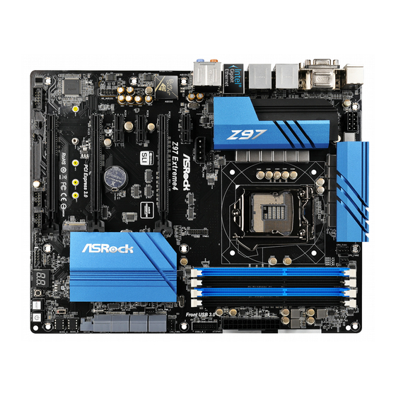
  • Seite 37 Z97 Extreme4/3.1 1 Einleitung Vielen Dank, dass Sie sich für das Z97 Extreme4/3.1 von ASRock entschieden haben – ein zuverlässiges Motherboard, das konsequent unter der strengen Qualitätskontrolle von ASRock hergestellt wurde. Es liefert ausgezeichnete Leistung mit robustem Design, das ASRocks Streben nach Qualität und Beständigkeit erfüllt.
  • Seite 38: Technische Daten

    Prozessoren (Sockel 1150) der 5., 4. und neuen 4. Generation • Digipower-Design • 12-Leistungsphasendesign • Unterstützt Intel® Turbo Boost 2.0-Technologie • Unterstützt CPUs mit freiem Multiplikator der Intel® K-Serie • Unterstützt ASRock BCLK-Übertaktung (voller Bereich) • Intel® Z97 Chipsatz • Dualkanal-DDR3-Speichertechnologie Speicher • 4 x DDR3-DIMM-Steckplätze...
  • Seite 39 DVI-D-, HDMI- und DisplayPort 1.2-Ports • 7.1-Kanal-HD-Audio mit Inhaltsschutz (Realtek ALC1150- Audio Audiocodec) • Erstklassige Blu-ray-Audiounterstützung • Unterstützt Überspannungsschutz (ASRock Full Spike Protec- tion) • Unterstützt Purity Sound - Nichicon-Audiokappen der Fine Gold-Serie - 115-dB-SRV-DAC mit Diferentialverstärker - TI® NE5532 – erstklassiger Headset-Verstärker (unterstützt...
  • Seite 40 • 2 x USB 3.0-Ports (ASMedia ASM1042AE) (unterstützt Schutz gegen elektrostatische Entladung (ASRock Full Spike Protection)) • 4 x USB 3.0-Ports (Intel® Z97) (unterstützt Schutz gegen elektrostatische Entladung (ASRock Full Spike Protection)) • 1 x RJ-45-LAN-Port mit LED (Aktivität/Verbindung-LED und Geschwindigkeit-LED) • HD-Audioanschlüsse: Hintere Lautsprecher / Zentral / Bass /...
  • Seite 41 Z97 Extreme4/3.1 • 6 x SATA-III-6,0-Gb/s-Anschlüsse per Intel® Z97, unterstützt Speicher RAID (RAID 0, RAID 1, RAID 5, RAID 10, Intel Rapid Storage Technology 13 und Intel Smart Response Technology), NCQ, AHCI, Hot-Plugging und ASRock HDD-Saver-Technologie • 2 x SATA-III-6,0-Gb/s-Anschlüsse von ASMedia ASM1061, unterstützt NCQ, AHCI, Hot-Plugging und ASRock HDD-...
  • Seite 42 Aufgrund von Beschränkungen kann die Größe des tatsächlich für die Systemnutzung reser- vierten Speichers unter Windows®-Betriebssystemen mit 32 Bit weniger als 4 GB betragen. Windows®-Betriebssysteme mit 64 Bit haben keine derartigen Beschränkungen. Mit ASRock XFast RAM können Sie den Speicher einsetzen, den Windows® nicht nutzen kann.
  • Seite 43: Jumpereinstellung

    Z97 Extreme4/3.1 1.3 Jumpereinstellung Die Abbildung zeigt, wie die Jumper eingestellt werden. Wenn die Jumper-Kappe auf den Kontakten angebracht ist, ist der Jumper „kurzgeschlossen“. Wenn keine Jumper- Kappe auf den Kontakten angebracht ist, ist der Jumper „ofen“. Die Abbildung zeigt einen 3-poligen Jumper, dessen Kontakt 1 und Kontakt 2 „kurzgeschlossen“...
  • Seite 44: Integrierte Stiftleisten Und Anschlüsse

    1.4 Integrierte Stiftleisten und Anschlüsse Integrierte Stitleisten und Anschlüsse sind KEINE Jumper. Bringen Sie KEINE Jumper-Kappen an diesen Stitleisten und Anschlüssen an. Durch Anbringen von Jumper-Kappen an diesen Stitleisten und Anschlüssen können Sie das Motherboard dauerhat beschädigen. Systemblende-Stitleiste Verbinden Sie PLED+ PLED- Netzschalter, Reset-Taste...
  • Seite 45 Z97 Extreme4/3.1 Betrieb-LED-Stitleiste Bitte verbinden Sie die (3-polig, PLED1) Betrieb-LED des Gehäuses PLED- PLED+ (siehe S. 1, Nr. 23) zur Anzeige des System- PLED+ betriebsstatus mit dieser Stitleiste. Serial-ATA-III-Anschlüsse Diese acht SATA-III- (SATA3_0) Anschlüsse unterstützen (siehe S. 1, Nr. 12) SATA-Datenkabel für...
  • Seite 46 USB_PWR USB 2.0-Stitleisten Neben zwei USB 2.0-Ports (9-polig, USB2_3) an der E/A-Blende DUMMY (siehe S. 1, Nr. 27) beinden sich zwei (9-polig, USB4_5) Stitleisten an diesem (siehe S. 1, Nr. 26) Motherboard. Jede USB 2.0-Stitleiste kann zwei USB_PWR Ports unterstützen. Vbus Vbus USB 3.0-Stitleiste...
  • Seite 47 Z97 Extreme4/3.1 Gehäuse- und Netz- Bitte verbinden Sie die teillüteranschlüsse Lüterkabel mit den FAN_SPEED_CONTROL CHA_FAN_SPEED (4-polig, CHA_FAN1) Lüteranschlüssen; der +12V (siehe S. 1, Nr. 9) schwarze Draht gehört (3-polig, CHA_FAN2) zum Erdungskontakt. (siehe S. 1, Nr. 35) (3-polig, CHA_FAN3) FAN_VOLTAGE (siehe S.
  • Seite 48 PCIe-Netzanschluss Bitte verbinden Sie ein 4-poliges (4-polig, PCIE_PWR1) Molex-Netzkabel mit diesem (siehe S. 1, Nr. 33) Anschluss, wenn mehr als drei +12V DETECT PCI Express-Karten installiert sind. HDD-Saver-Anschluss Bitte verbinden Sie zum Verwalten (4-polig, SATA_PWR_1) des Energiestatus der Festplatte (siehe S. 1, Nr. 8) das HDD-Saver-Kabel mit diesem Anschluss.
  • Seite 49: Intelligente Schalter

    Z97 Extreme4/3.1 1.5 Intelligente Schalter Das Motherboard hat vier intelligente Schalter: Ein-/Ausschalter, Reset-Schalter, CMOS-löschen-Schalter und BIOS-Auswahlschalter, wodurch Benutzer das System schnell ein-/abschalten, zurücksetzen, die CMOS-Werte löschen oder von einem anderen BIOS starten können. Ein-/Ausschalter Mit dem Ein-/Ausschalter (PWRBTN1) kann der Benutzer das (siehe S.
  • Seite 50: Contenu De L'emballage

    à modiication sans préavis. En cas de modiications du présent document, la version mise à jour sera disponible sur le site Internet ASRock sans notiication préalable. Si vous avez besoin d’une assistance technique pour votre carte mère, veuillez visiter notre site Internet pour plus de détails sur le modèle que vous utilisez.
  • Seite 51 • Prend en charge la technologie Intel® Turbo Boost 2.0 • Prend en charge les processeurs débloqués de la série K Intel® • Prend en charge l’ o verclocking ASRock BCLK Full-range • Intel® Z97 Chipset • Technologie mémoire double canal DDR3 Mémoire...
  • Seite 52 Audio Realtek ALC1150) • Compatible audio Blu-ray Premium • Protection contre les surtensions (Protection complète contre les pics ASRock) • Prend en charge Purity Sound - Couvercles audio série en or in Nichicon - 115dB SNR DAC avec ampliicateur diférentiel - Ampliicateur de casque TI®...
  • Seite 53 • 2 x ports USB 3.0 (ASMedia ASM1042AE) (Protection contre les décharges électrostatiques (Protection complète contre les pics ASRock)) • 4 x ports USB 3.0 (Intel® Z97) (Protection contre les décharges électrostatiques (Protection complète contre les pics ASRock)) • 1 x port RJ-45 LAN avec LED (LED ACT/LIEN et LED VITESSE) • Connecteurs jack audio HD : Haut-parleur arrière / central...
  • Seite 54 • 6 x connecteurs SATA3 6,0 Gb/s par Intel® Z97, compatibles Stockage RAID (RAID 0, RAID 1, RAID 5, RAID 10, technologies Intel Rapid Storage 13 et Intel Smart Response), NCQ, AHCI, « Hot Plug » et sauvegarde HDD ASRock • 2 x connecteurs SATA3 6,0 Go/s ASMedia ASM1061, compatibles avec les fonctions NCQ, AHCI, « Hot Plug »...
  • Seite 55 Certiications • ErP/EuP Ready (alimentation ErP/EuP ready requise) * pour des informations détaillées de nos produits, veuillez visiter notre site : http://www.asrock.com Il est important de signaler que l'overcloking présente certains risques, incluant des modiica- tions du BIOS, l’ a pplication d’une technologie d’ o verclocking déliée et l'utilisation d'outils d'overclocking développés par des tiers.
  • Seite 56 1.3 Coniguration des cavaliers (jumpers) L’illustration ci-dessous vous renseigne sur la coniguration des cavaliers (jumpers). Lorsque le capuchon du cavalier est installé sur les broches, le cavalier est ‘court-circuité’ . Si le capuchon du cavalier n’ e st pas installé sur les broches, le cavalier est ‘ouvert’ . L’illustration représente un cavalier à...
  • Seite 57 Z97 Extreme4/3.1 1.4 Embases et connecteurs de la carte mère Les embases et connecteurs situés sur la carte NE SONT PAS des cavaliers. Ne placez JAMAIS de capuchons de cavaliers sur ces embases ou connecteurs. Placer un capuchon de cavalier sur ces embases ou connecteurs endommagera irrémédiablement votre carte mère.
  • Seite 58 (SATA3_4) Express. (voir p.1, No. 15) Pour minimiser le temps (SATA3_5) au démarrage, utilisez les (voir p.1, No. 17) ports Intel® Z97 SATA (SATA3_A0) (SATA3_0) pour vos (voir p.1, No. 10) appareils démarrables. (SATA3_A1) (voir p.1, No. 11) Connecteur série ATA...
  • Seite 59 Z97 Extreme4/3.1 Vbus Vbus Embases USB 3.0 Cette carte mère est Vbus IntA_PB_SSRX- (USB3_0_1 19 broches) dotée d’une embase IntA_PB_SSRX+ IntA_PA_SSRX- IntA_PA_SSRX+ (voir p.1, No. 7) supplémentaire. Chaque IntA_PB_SSTX- embase USB 3.0 peut IntA_PA_SSTX- IntA_PB_SSTX+ IntA_PA_SSTX+ prendre en charge deux IntA_PB_D- ports.
  • Seite 60 Connecteurs du Cette carte mère est dotée FAN_SPEED_CONTROL FAN_SPEED ventilateur du processeur d’un connecteur pour + 12V GN D (CPU_FAN1 à 4 broches) ventilateur de processeur (voir p.1, No. 2) (Quiet Fan) à 4 broches. Si vous envisagez de FAN_SPEED (CPU_FAN2 à...
  • Seite 61 Z97 Extreme4/3.1 RRXD1 Embase pour port série Cette embase COM1 prend DDTR#1 DDSR#1 (COM1 à 9 broches) en charge un module de CCTS#1 (voir p.1, No. 30) port série. RRI#1 RRTS#1 TTXD1 DDCD#1 Embase TPM Ce connecteur prend en (TPMS1 à 17 broches) charge un module TPM (voir p.1, No.
  • Seite 62 1.5 Boutons intelligents La carte mère est équipée de quatre boutons intelligents : bouton de mise en marche, bouton de réinitialisation, bouton d’ e facement CMOS et bouton de sélecteur de BIOS qui permettent aux utilisateurs d’allumer/éteindre le système, de réinitialiser le système, d’...
  • Seite 63: Contenuto Della Confezione

    Web di ASRock senza ulteriore preavviso. Per il supporto tecnico correlato a questa scheda madre, visitare il nostro sito Web per informazioni speciiche relative al modello attualmente in uso.
  • Seite 64 • Design Digi Power • Potenza a 12 fasi • Supporta la tecnologia Intel® Turbo Boost 2.0 • Supporto di CPU unlocked Intel® K-Series • Supporta gamma completa overclocking BCLK ASRock • Intel® Z97 Chipset • Tecnologia con memoria DDR3 a doppio canale Memoria • 4 alloggi DIMM DDR3...
  • Seite 65 Audio Realtek ALC1150) • Supporto audio Blu-ray Premium • Supporto protezione da sovratensione (protezione completa ASRock dai picchi di corrente) • Supporto di Purity Sound - Cappucci audio Nichicon serie Fine Gold - 115dB SNR DAC con ampliicatore diferenziale - TI® NE5532 Premium Headset Ampliier (supporta cuie ino...
  • Seite 66 • 2 x Porte USB 3.0 (ASMedia ASM1042AE) (supporto protezione da scariche elettrostatiche (ESD) (protezione completa ASRock dai picchi di corrente)) • 4 x Porte USB 3.0 (Intel® Z97) (supporto protezione da scariche elettrostatiche (ESD) (protezione completa ASRock dai picchi di corrente)) • 1 x porta LAN RJ-45 con LED (ACT/LINK LED e SPEED...
  • Seite 67 Z97 Extreme4/3.1 • 6 x Connettori SATA3 6,0 Gb/s Intel® Z97, supportano RAID Archiviazi- (RAID 0, RAID 1, RAID 5, RAID 10, Intel Rapid Storage Tech- nology 13 e Intel Smart Response Technology), NCQ, AHCI, Hot Plug e tecnologia ASRock HDD Saver • 2 x Connettori SATA3 6,0Gb/s ASMedia ASM1061, supportano...
  • Seite 68 Windows® a 32 bit. I sistemi operativi Win- dows® a 64 bit non possiedono tali limitazioni. È possibile utilizzare la RAM XFast di ASRock per utilizzare la memoria che Windows® non può utilizzare.
  • Seite 69 Z97 Extreme4/3.1 1.3 Impostazione jumper L'illustrazione mostra in che modo vengono impostati i jumper. Quando il cappuccio del jumper è posizionato sui pin, il jumper è "cortocircuitato". Se sui pin non è posizionato alcun cappuccio del jumper, il jumper è "aperto". L'illustrazione mostra un jumper a 3 pin i cui pin1 e pin2 sono "cortocircuitati"...
  • Seite 70 1.4 Header e connettori sulla scheda Gli header e i connettori sulla scheda NON sono jumper. NON posizionare cappucci del jumper su questi header e connettori. Il posizionamento di cappucci del jumper su header e connettori provocherà danni permanenti alla scheda madre. Header sul pannello del Collegare l'interruttore PLED+...
  • Seite 71 SATA Express. (vedere pag. 1, n. 15) Per ridurre al minimo il (SATA3_5) tempo d’avvio, usare le vedere pag.1, n. 17) porte SATA Intel ® Z97 (SATA3_A0) (SATA3_0) per i dispositivi vedere pag.1, n. 10) di’avvio. (SATA3_A1) vedere pag.1, n. 11)
  • Seite 72 Header USB 3.0 Oltre alle sei porte USB 3.0 Vbus Vbus Vbus IntA_PB_SSRX- (19-pin USB3_0_1) del pannello I/O, questa IntA_PA_SSRX- IntA_PB_SSRX+ IntA_PA_SSRX+ (vedere pag. 1, n. 7) scheda madre è dotata IntA_PB_SSTX- IntA_PA_SSTX- IntA_PB_SSTX+ di un collettore. Ciascun IntA_PA_SSTX+ IntA_PB_D- header USB 3.0 può...
  • Seite 73 Z97 Extreme4/3.1 Connettori ventola dello Collegare i cavi della chassis e di alimentazione ventola ai connettori della FAN_SPEED_CONTROL CHA_FAN_SPEED (CHA_FAN1 a 4 pin) ventola e far corrispondere +12V (vedere pag. 1, n. 9) il ilo nero al pin di terra.
  • Seite 74 Connettore alimentazione Collegare un cavo di PCIe alimentazione molex a 4 pin a (4-pin PCIE_PWR1) questo connettore quando sono (vedere pag. 1, n. 33) installate più di tre Schede PCI +12V DETECT Express. Connettore HDD Saver Collegare il cavo HDD Saver a (4-pin SATA_PWR_1) questo connettore per gestire lo (vedere pag.
  • Seite 75 Z97 Extreme4/3.1 1.5 Interruttori intuitivi La scheda madre è dotata di quattro interruttori intuitivi: Interruttore d’alimentazione, interruttore di ripristino, interruttore Clear CMOS ed interruttore di selezione BIOS che consentono di accendere/spegnere rapidamente il sistema, ripristinare il sistema, cancellare i valori CMOS oppure eseguire l’avvio su un BIOS diverso.
  • Seite 76: Contenido Del Paquete

    Si esta documentación sufre alguna modiicación, la versión actualizada estará disponible en el sitio web de ASRock sin previo aviso. Si necesita asistencia técnica relacionada con esta placa base, visite nuestro sitio web para obtener información especíica sobre el modelo que esté...
  • Seite 77 • Compatible con la tecnología de Intel® Turbo Boost 2.0 • Compatible con CPU serie K desbloqueada de Intel® • Compatible con overclocking de rango completo BCLK de ASRock • Intel® Z97 Conjunto de chips • Tecnología de memoria de Doble Canal DDR3 Memoria • 4 ranuras DDR3 DIMM...
  • Seite 78 • La Tecnología visual integrada de gráicos HD de Intel® y las Gráicos salidas de VGA son compatibles únicamente con procesadores con GPU integrado. • Compatible con la Tecnología visual integrada de gráicos HD de Intel®: Intel® Quick Sync Video con AVC, MVC (S3D) y MPEG-2 Full HW Encode1, Intel®...
  • Seite 79 • 2 puertos USB 3.0 (ASMedia ASM1042AE) (compatible con protección contra electricidad estática (protección ASRock Full Spike)) • 4 puertos USB 3.0 (Intel® Z97) (compatible con protección contra electricidad estática (protección ASRock Full Spike)) • 1 puerto LAN RJ-45 con LED (ACT/LINK LED y SPEED LED) • Conector de audio HD: Altavoz trasero / Central / Graves /...
  • Seite 80 • 1 x Puerto USB 3.1 Tipo C por (10 Gb/s) (admite protección ESD, es decir, protección total contra picos ASRock) • 6 conectores SATA3 de 6 Gb/s de Intel® Z97, compatibilidad Alma- con RAID (RAID 0, RAID 1, RAID 5, RAID 10, Intel Rapid...
  • Seite 81 Windows® de 32 bits. Los sitemas opera- tivos Windows® de 64 bits no tienen estas limitaciones. Podrá utilizar XFast RAM de ASRock para usar la memoria que Windows® no puede utilizar.
  • Seite 82 1.3 Instalación de los puentes La instalación muestra cómo deben instalarse los puentes. Cuando la tapa de puente se coloca en los pines, el puente queda “Corto”. Si no coloca la tapa de puente en los pines, el puente queda “Abierto”. La ilustración muestra un puente de 3 pines cuyo pin 1 y pin 2 son “Cortos”...
  • Seite 83 Z97 Extreme4/3.1 1.4 Conectores y cabezales incorporados Los cabezales y conectores incorporados NO son puentes. NO coloque tapas de puente sobre estos cabezales y conectores. Si coloca tapas de puente sobre los cabezales y conectores dañará de forma permanente la placa base.
  • Seite 84 SATA. (SATA3_5) Para reducir el tiempo consulte la pág.1, N.º 17) de arranque, utilice (SATA3_A0) puertos SATA Z97 de consulte la pág.1, N.º 10) Intel® (SATA3_0) con sus (SATA3_A1) dispositivos de arranque. consulte la pág.1, N.º 11) Conector express serie...
  • Seite 85 Z97 Extreme4/3.1 Cabezal USB 3.0 Vbus Vbus Esta placa base contiene un Vbus IntA_PB_SSRX- (USB3_0_1 de 19 pines) cabezal. Cada cabezal USB IntA_PA_SSRX- IntA_PB_SSRX+ IntA_PA_SSRX+ (consulte la pág.1, N.º 7) 3.0 admite dos puertos. IntA_PB_SSTX- IntA_PA_SSTX- IntA_PB_SSTX+ IntA_PA_SSTX+ IntA_PB_D- IntA_PA_D-...
  • Seite 86 Conectores del ventilador Conecte los cables del de alimentación y del ventilador a los conectores FAN_SPEED_CONTROL CHA_FAN_SPEED chasis del ventilador y haga +12V (CHA_FAN1 de 4 pines) coincidir el cable negro (consulte la pág.1, N.º 9) con el pin de conexión a (CHA_FAN2 de 3 pines) tierra.
  • Seite 87 Z97 Extreme4/3.1 Conector de alimentación Conecte a este conector un cable PCIe de alimentación molex de 4 pines (PCIE_PWR1 de 4 pines) cuando se instalen más de tres (consulte la pág.1, N.º 33) Tarjetas PCI Express. +12V DETECT Conector de ahorro de Conecte el cable de ahorro HDD energía HDD...
  • Seite 88 1.5 Interruptores inteligentes La placa base contiene cuatro interruptores inteligentes: Interruptor de alimentación, interruptor de reseteo, interruptor de borrado de CMOS e interruptor de selección BIOS, que permiten a los usuarios encender y apagar rápidamente el sistema, resetearlo, borrar los valores de CMOS, o arrancar desde un BIOS diferente. Interruptor de El interruptor de alimentación...
  • Seite 89: Комплект Поставки

    уведомления. При необходимости технической поддержки, связанной с материнской платой, посетите веб-сайт и найдите на нем информацию о модели используемой вами материнской платы. На веб-сайте ASRock также можно найти самый последний перечень поддерживаемых VGA-карт и ЦП. Веб-сайт ASRock http://www.asrock.com. 1.1 Комплект поставки...
  • Seite 90 • Digi Power design • Система питания 12 • Поддержка технологии Intel® Turbo Boost 2.0 • Поддержка процессоров Intel® серии K с разблокированным множителем • Поддержка полного разгона процессора ASRock BCLK • Intel® Z97 Чипсет • Двухканальная память DDR3 Память...
  • Seite 91 • 7.1-канальный звук высокой четкости HD Audio с Аудио защитой данных (аудиокодек Realtek ALC1150) • Поддержка Premium Blu-ray Audio • Защита от перенапряжения (ASRock Full Spike Pro- tection) • Поддержка Purity Sound - Конденсаторы для аудиосистем серии Nichicon Fine Gold - 115 дБ...
  • Seite 92 • 2 x Порты USB 3.0 (ASMedia ASM1042AE) с защитой от электростатического напряжения (ASRock Full Spike Protection) • 4 x Порты USB 3.0 (Intel® Z97) с защитой от электростатического напряжения (ASRock Full Spike Protection) • 1 x RJ-45 для ЛВС с СИД (СИД ACT/LINK и МИД...
  • Seite 93 Z97 Extreme4/3.1 • 6 x Разъемы SATA3 со скоростью обмена данными Запоминающие 6,0 ГБ/с с Intel® Z97, технологии RAID (RAID 0, RAID устройства 1, RAID 5, RAID 10, Intel Rapid Storage Technology 13 и Intel Smart Response Technology), NCQ, AHCI, "горячего"...
  • Seite 94 вызванный разгоном процессора. В связи с ограничением при работе под 32-разрядной ОС Windows® фактический объем памяти может быть меньше 4 Гбайт. Для 64-разрядных ОС Windows® таких ограничений нет. Для использования той памяти, которую ОС Windows® не может использовать, используйте ASRock XFast RAM.
  • Seite 95 Z97 Extreme4/3.1 1.3 Установка перемычек Установка перемычек показана на рисунке. При установке колпачковой перемычки на контакты перемычка «замкнута». Если колпачковая перемычка на контакты не установлена, перемычка «разомкнута». На рисунке показана 3-контактная перемычка с замкнутыми контактами 1 и 2 при установке на них...
  • Seite 96 1.4 Колодки и разъемы, расположенные на материнской плате Расположенные на материнской плате колодки и разъемы перемычками НЕ являются. НЕ устанавливайте на эти колодки и разъемы колпачковые перемычки. Установка колпачковых перемычек на эти колодки и разъемы может вызвать неустранимое повреждение материнской платы. Колодка...
  • Seite 97 разъемом SATA Express. (См. стр. 1, № 15) Для минимизации (SATA3_5) времени загрузки см. стр.1, № 17) используйте порты Intel® (SATA3_A0) Z97 SATA (SATA3_0) см. стр.1, № 10) для самозагружаемых (SATA3_A1) устройств. см. стр.1, № 11) Разъем SATA Express К данному разъему...
  • Seite 98 Vbus Vbus Колодка USB 3.0 На данной системной Vbus IntA_PB_SSRX- (19-контактная плате имеется одна IntA_PB_SSRX+ IntA_PA_SSRX- IntA_PA_SSRX+ USB3_0_1) колодка. Каждая IntA_PB_SSTX- (См. стр. 1, № 7) колодка USB 3.0 может IntA_PA_SSTX- IntA_PB_SSTX+ IntA_PA_SSTX+ поддерживать два порта. IntA_PB_D- IntA_PA_D- IntA_PB_D+ IntA_PA_D+ Dummy Аудиоколодка...
  • Seite 99 Z97 Extreme4/3.1 Разъемы для Предназначены для вентиляторов корпуса и подключения кабелей FAN_SPEED_CONTROL CHA_FAN_SPEED блока питания разъемов вентиляторов +12V (4-контактный, CHA_ и подключения черного FAN1) провода к заземлению. (См. стр. 1, № 9) (3-контактный, CHA_ FAN2) FAN_VOLTAGE CHA_FAN_SPEED (См. стр. 1, № 35) (3-контактный, CHA_...
  • Seite 100 Разъем питания PCIe При установке более трех PCI (4-контактный PCIE_ Express карты подключите к PWR1) данному разъему 4-контактный (См. стр. 1, № 33) кабель Molex. +12V DETECT Разъем HDD Saver Для управления режимом (4-контактный SATA_ питания жесткого диска PWR_1) подключите к данному разъему (См.
  • Seite 101 Z97 Extreme4/3.1 1.5 Электронные кнопки На системной плате размещены четыре электронных переключателя: выключатель питания, кнопка сброса, кнопка очистки КМОП и селекторный переключатель BIOS, позволяющие быстро включать/выключать систему, сбрасывать систему, очищать параметры КМОП или загружаться с другой BIOS. Кнопка питания Кнопка питания...
  • Seite 102: Conteúdo Da Embalagem

    Se precisar de assistência técnica relacionada a esta placa principal, visite o nosso site para obter informações especíicas sobre o modelo que estiver utilizando. Você também poderá encontrar a lista de placas VGA e CPU mais recentes suportadas no site da ASRock. Site da ASRock http://www.asrock.com.
  • Seite 103 • Design com 12 fases de alimentação • Suporta a tecnologia Intel® Turbo Boost 2.0 • Suporta CPU desbloqueado da série K da Intel® • Suporta Overclocking total ASRock BCLK • Intel® Z97 Chipset • Tecnologia de memória DDR3 de dois canais Memória...
  • Seite 104 Áudio áudio Realtek ALC1150) • Suporte áudio Blu-ray superior • Suporta proteção contra sobretensão (Proteção Total Contra Picos ASRock) • Suporta Purity Sound - Capacitor de Áudio Série Ouro Fino Nichicon - 115dB SNR DAC com ampliicador diferencial - Ampliicador de Fone de Ouvido TI® NE5532 Premium (su- porta fones de ouvido de até...
  • Seite 105 • 2 x Portas USB 3.0 (ASMedia ASM1042AE)(Suporta Proteção ESD (Proteção Total Contra Picos ASRock)) • 4 x Portas USB 3.0 Intel® Z97 (Suporta Proteção ESD (Proteção Total Contra Picos ASRock)) • 1 x Porta LAN RJ-45 com LED (LED ACT/LINK e LED DE VELOCIDADE) • Fichas de áudio HD: Alto-falante posterior / Central / Graves /...
  • Seite 106 • 6 x Conectores SATA3 6,0 Gb/s da Intel® Z97, suporte RAID Armazena- mento (RAID 0, RAID 1, RAID 5, RAID 10, Tecnologia de Armaze- namento Rápido Intel® 13 e Tecnologia de Resposta Inteligente Intel), NCQ, AHCI e Conexão a Quente e Tecnologia Protetora de HDD ASRock • 2 x Conectores SATA3 6,0 Gb/s ASMedia ASM1061, suporte...
  • Seite 107 * Para obter informações detalhadas sobre o produto, por favor, visite o nosso site: http://www.asrock.com Por favor, observe que existe um certo risco envolvendo overclocking, incluindo o ajuste das deinições na BIOS, a aplicação de tecnologia Untied Overclocking ou a utilização de ferra- mentas de overclocking de terceiros.
  • Seite 108 1.3 Coniguração dos jumpers A imagem abaixo mostra como os jumpers são conigurados. Quando a tampa do jumper é colocada nos pinos, o jumper é "Curto". Se não for colocada uma tampa de jumper nos pinos, o jumper é "Aberto". A imagem mostra um jumper de 3 pinos cujos pino1 e pino2 estão "Curtos"...
  • Seite 109 Z97 Extreme4/3.1 1.4 Suportes e conectores onboard Os conectores e suportes onboard NÃO são jumpers. NÃO coloque tampas de jumpers sobre estes terminais e conectores Colocar tampas de jumpers sobre os terminais e conectores irá causar danos permanentes à placa-mãe.
  • Seite 110 (ver p.1, N.º 15) conector SATA Express. (SATA3_5) Para minimizar o tempo ver p.1, N.º 17) de inicialização, use (SATA3_A0) portas Intel® Z97 SATA ver p.1, N.º 10) (SATA3_0) para os seus (SATA3_A1) dispositivos inicializáveis. ver p.1, N.º 11) Conector Serial ATA...
  • Seite 111 Z97 Extreme4/3.1 Suporte USB 3.0 Vbus Vbus Existe uma plataforma nesta Vbus IntA_PB_SSRX- (USB3_0_1 19-pinos) placa-mãe. Cada suporte USB 3.0 IntA_PA_SSRX- IntA_PB_SSRX+ IntA_PA_SSRX+ (ver p.1, N.º 7) pode suportar duas portas. IntA_PB_SSTX- IntA_PA_SSTX- IntA_PB_SSTX+ IntA_PA_SSTX+ IntA_PB_D- IntA_PA_D- IntA_PB_D+ IntA_PA_D+ Dummy Suporte de áudio do painel...
  • Seite 112 Conectores do ventilador Esta placa mãe inclui um FAN_SPEED_CONTROL FAN_SPEED da CPU conector de ventilador + 12V GN D (CPU_FAN1 de 4 pinos) da CPU (Ventilador (ver p.1, N.º 2) silencioso) de 4 pinos. Se você pretende conectar um FAN_SPEED (CPU_FAN2 de 3 pinos) ventilador da CPU de 3 + 12V...
  • Seite 113 Z97 Extreme4/3.1 RRXD1 Suporte da porta serial Este suporte COM1 recebe DDTR#1 DDSR#1 (COM1 de 9 pinos) um módulo da porta serial. CCTS#1 (ver p.1, N.º 31) RRI#1 RRTS#1 TTXD1 DDCD#1 Terminal TPM Este conector suorta (TPMS1 de 17 pinos) sistema Trusted Platform (ver p.1, N.º...
  • Seite 114 1.5 Interruptores inteligentes A placa-mãe tem quatro chaves inteligentes: Chave liga/desliga, Chave de Reset, Chave para Limpar CMOS e uma Chave de Seleção da BIOS, que permite aos usuários rapidamente ligar/desligar o sistema, reiniciar o sistema, limpar os valores de CMOS ou inicializar de BIOS diferentes.
  • Seite 115: Ambalaj İçeriği

    Bu dokümantasyon üzerinde herhangi bir değişiklik yapılması halinde, güncellenmiş sürüm, herhangi bir bildirim yapılmaksızın ASRock'ın web sitesinde yer alacaktır.. Bu anakart ile ilgili olarak teknik destek almak istiyorsanız, lütfen kullandığınız model hakkında özel bilgiler için web sitemizi ziyaret edin.
  • Seite 116 • Dijital Güç tasarımı • 12 Güç Sahası tasarımı • Intel® Turbo Boost 2.0 Teknolojisini destekler • Intel® K Serisi kilitsiz işlemcileri destekler • ASRock BCLK tam aralıklı Hız Aşırtmayı destekler • Intel® Z97 Yonga kümesi • Çit Kanallı DDR3 Bellek Teknolojisi Bellek • 4 x DDR3 DIMM Yuvası...
  • Seite 117 Z97 Extreme4/3.1 • Intel® HD Graphics Dahili Görselleri ile VGA çıktıları, yalnızca Graikler GPU entegre edilmiş işlemciler ile desteklenir. • Intel® HD Graphics Dahili Görsellerini destekler : AVC, MVC (S3D) ve MPEG-2 Full HW Encode1, Intel® InTru 3D, Intel® Net Video HD Teknolojisi, Intel® Insider , Intel®...
  • Seite 118 • 2 x USB 3.0 Bağlantı Noktası (ASMedia ASM1042AE) (ESD Koruması Destekler (ASRock Tam Ani Gerilim Koruması)) • 4 x USB 3.0 Bağlantı Noktası (Intel® Z97) (ESD Koruması Destekler (ASRock Tam Ani Gerilim Koruması)) • LED'e sahip 1 x RJ-45 LAN Bağlantı Noktası (ACT/LINK LED ve SPEED LED) • HD Ses Jakları: Arka Hoparlör / Merkezi / Bas / Hat Girişi / Ön...
  • Seite 119 • 1 x USB 3.1 Tip-C Bağlantı (10 Gb/s) Noktası (ESD Korumasını Destekler (ASRock Tam Ani Voltaj Yükselme Koruması)) • 6 x SATA3 6,0 Gb/s Bağlayıcısı, Intel® Z97 tarafından, RAID Depolama (RAID 0, RAID 1, RAID 5, RAID 10, Intel Rapid Storage Technology 13 ve Intel Smart Response Technology), NCQ, AHCI, Tak Çıkar ve ASRock Sabit Disk Kaydedici Teknolojisi...
  • Seite 120 • ErP/EuP için hazır (ErP/EuP için hazır güç beslemesi ger- eklidir) * Detaylı ürün bilgisi için, lütfen web sitemizi ziyaret edin: http://www.asrock.com Lütfen, BIOS ayarlarını düzenleme, Bağımsız Hız Aşırtma Teknolojinin uygulanması ya da üçüncü kişilerin hız aşırtma araçlarının kullanılması da dahil olmak üzere tüm hız aşırtma işlemlerinin belirli bir risk taşıdığını...
  • Seite 121 Z97 Extreme4/3.1 1.3 Bağlantı Teli Kurulumu Çizim, bağlantı tellerinin kurulumunu göstermektedir. Tel kapağı, pimlerin üzerine yerleştirildiğinde, tel "Kısa" olur. Pimlerin üzerinde tel kapağı bulunmadığında, tel "Açık" olur. Çizim, pin1 ve pin2 alanları "Kısa" olan ve bu iki pim üzerinde bir bağlantı...
  • Seite 122 1.4 Ekli Bağlantılar ve Bağlayıcılar Ekli bağlantılar ve bağlayıcılar bağlantı teli değildir. Bağlantı teli kapaklarını bu bağlantı ve bağlayıcılar üzerine yerleştirmeyin. Bağlantı teli kapaklarının bağlantılar ile bağlayıcılar üzerine yerleştirilmesi, anakarta kalıcı hasar verebilir. Sistem Paneli Bağlantısı Güç anahtarını bağlayın, PLED+ PLED- (9-pin PANEL1) kasa üzerindeki anahtar ile...
  • Seite 123 (SATA3_4) Başlatma süresini en (bkz. sf.1, No. 15) aza indirmek için, (SATA3_5) çalıştırılabilir aygıtlar için (bkz. sf.1, No. 17) Intel® Z97 SATA bağlantı (SATA3_A0) noktalarını (SATA3_0) (bkz. sf.1, No. 10) kullanın. (SATA3_A1) (bkz. sf.1, No. 11) Seri ATA Express Bu bağlayıcıya lütfen ya...
  • Seite 124 USB 3.0 Bağlantı Vbus Vbus Bu anakart üzerinde Vbus IntA_PB_SSRX- (19 pimli USB3_0_1) bir adet bağlantı IntA_PA_SSRX- IntA_PB_SSRX+ IntA_PA_SSRX+ (bkz. sf.1, No. 7) bulunmaktadır. Her IntA_PB_SSTX- IntA_PA_SSTX- IntA_PB_SSTX+ USB 3.0 bağlantısı, iki IntA_PA_SSTX+ adet bağlantı noktasını IntA_PB_D- IntA_PA_D- IntA_PB_D+ destekleyebilir. IntA_PA_D+ Dummy OUT_RET...
  • Seite 125 Z97 Extreme4/3.1 Kasa ve Güç Fanı Lütfen fan kablolarını Bağlayıcıları fan bağlayıcılarına takın FAN_SPEED_CONTROL CHA_FAN_SPEED (4-pin CHA_FAN1) ve siyah teli topraklama +12V (bkz sf.1, No. 9) pinine bağlayın. (3-pin CHA_FAN2) (bkz sf.1, No. 35) (3-pin CHA_FAN3) FAN_VOLTAGE (bkz sf.1, No. 34)
  • Seite 126 Sabit Disk Kaydedici Sabit diskin güç durumunu Bağlayıcısı yönetmek için lütfen bu (4 pimli SATA_PWR_1) bağlayıcıya Sabit Disk Kaydedici (bkz. sf.1, No. 8) Kablosu bağlayın. RRXD1 Seri Bağlantı Noktası Bu COM1 bağlantısı seri DDTR#1 DDSR#1 Bağlantısı bağlantı yuvası modülünü CCTS#1 (9-pin COM1) destekler.
  • Seite 127 Z97 Extreme4/3.1 1.5 Akıllı Anahtar Anakartta dört adet akıllı düğme bulunur: Güç Düğmesi, Sıfırlama Düğmesi, CMOS Temizleme Düğmesi ve BIOS Seçim Anahtarı kullanıcıların sistemi hızlı bir şekilde açıp kapatmalarını, sistemi sıfırlamalarını, CMOS değerlerini temizlemelerini ya da farklı BIOS'tan yüklemelerini sağlar.
  • Seite 128 를 제공합니다 . 마더보드 규격과 BIOS 소프트웨어를 업데이트할 수도 있기 때문에 , 이 문서의 내용은 예고 없이 변경될 수 있습니다 . 이 설명서가 변경될 경우 , 업데이트된 버전은 ASRock 의 웹사이트에서 추가 통지 없이 제공됩니다 . 이 마더보드와 관련하여 기술적 지원이...
  • Seite 129 • Digi 전원 구조 • 12 개 전원 위상 구조 • Intel® Turbo Boost 2.0 기술 지원 • Intel®K- 시리즈 잠금 해제 CPU 지원 • ASRock BCLK 전범위 오버클로킹 지원 • Intel® Z97 칩세트 • 듀얼 채널 DDR3 메모리 기술...
  • Seite 130 • 콘텐츠 보호를 이용한 7.1 CH HD 오디오 지원 (Realtek 오디오 ALC1150 오디오 코덱 ) • 프리미엄 Blu-ray 오디오 지원 • 서지 보호 지원 (ASRock 풀 스파이크 보호 ) • Purity Sound 2 지원 - Nichicon Fine Gold 시리즈 오디오 캡...
  • Seite 131 • USB 3.0 포트 2 개 (ASMedia ASM1042AE)(ESD 보호 지원 (ASRock 풀 스파이크 보호 )) • USB 3.0 포트 4 개 (Intel® Z97)(ESD 보호 지원 (ASRock 풀 스 파이크 보호 )) • LED 장착 RJ-45 LAN 포트 1 개 (ACT/LINK LED 및 SPEED LED) •...
  • Seite 132 • Intel® Z97 지원 SATA3 6.0 Gb/s 커넥터 6 개가 RAID (RAID 저장 장치 0, RAID 1, RAID 5, RAID 10, Intel 빠른 저장 기술 13 및 Intel 스마트 응답 기술 ), NCQ, AHCI, 핫 플러그 및 ASRock HDD 세이버 기술을 지원...
  • Seite 133 제한 때문에 실제 메모리 크기는 Windows® 32 비트 운영체제 하의 시스템 사용을 위한 예비 메모리용 4GB 보다 더 적을 수 있습니다 . Windows® 64 비트 운영체제에는 그러 한 제한이 없습니다 . ASRock XFast RAM 을 사용하여 Windows® 가 사용할 수 없는 메 모리를 이용할 수 있습니다 .
  • Seite 134 1.3 점퍼 설정 그림은 점퍼를 어떻게 설정하는지 보여줍니다 . 점퍼 캡을 핀에 씌우면 점퍼가 “단락”됩니다 . 점퍼 캡을 핀에 씌우지 않으면 점퍼가 “단선”됩니다 . 그림 은 3 핀 점퍼를 보여주며 핀 1 과 핀 2 는 점퍼 캡을 씌울 때 “단락”됩니다 . Clear CMOS 점퍼...
  • Seite 135 Z97 Extreme4/3.1 1.4 온보드 헤더 및 커넥터 온보드 헤더와 커넥터는 점퍼가 아닙니다 . 점퍼 캡을 온보드 헤더와 커넥터에 씌우지 마십시오 . 점퍼 캡을 온보드 헤더와 커넥터에 씌우면 마더보드가 영구적으로 손상됩 니다 . 시스템 패널 헤더 섀시의 전원 스위치 , PLED+...
  • Seite 136 (1 페이지 , 15 번 항목 참조 ) 부팅 시간을 최소 화하려면 , Intel® (SATA3_5) (1 페이지 , 17 번 항목 참조 ) Z97 SATA 포트 (SATA3_0) 를 부팅용 (SATA3_A0) (1 페이지 , 10 번 항목 참조 ) 장치에 사용하십시...
  • Seite 137 Z97 Extreme4/3.1 Vbus Vbus USB 3.0 헤더 이 마더보드에는 헤 Vbus IntA_PB_SSRX- IntA_PA_SSRX- IntA_PB_SSRX+ (19 핀 USB3_0_1) 더가 한 개 탑재되어 IntA_PA_SSRX+ (1 페이지 , 7 번 항목 참조 ) 있습니다 . 각 USB 3.0 IntA_PB_SSTX- IntA_PA_SSTX- IntA_PB_SSTX+ 헤더는 포트 두 개를...
  • Seite 138 섀시 및 전원 팬 커넥터 팬 케이블을 팬 커넥 (4 핀 CHA_FAN1) 터에 연결하고 검은 FAN_SPEED_CONTROL CHA_FAN_SPEED (1 페이지 , 9 번 항목 참조 ) 색 와이어를 접지핀 +12V (3 핀 CHA_FAN2) 에 연결하십시오 . (1 페이지 , 35 번 항목 참조 ) (3 핀...
  • Seite 139 Z97 Extreme4/3.1 PCIe 전원 커넥터 세 이상의 PCI Express 카드 (4 핀 PCIE_PWR1) 설치되어 있을 때 4 핀 몰렉 (1 페이지 , 33 번 항목 참조 ) 스 전원 케이블을 이 커넥터 에 연결하십시오 . +12V DETECT HDD 세이버 커넥터...
  • Seite 140 1.5 스마트 스위치 마더보드에는 스마트 스위치 네 개가 탑재되어 있습니다 : 전원 스위치 , 리셋 스 위치 , CMOS 초기화 스위치 및 BIOS 선택 스위치 . 이 스위치들로 시스템을 빨리 켜고 끄거나 시스템을 리셋하거나 CMOS 값을 지우거나 다른 BIOS 로 부팅할 수 있습니다...
  • Seite 141 Z97 Extreme4/3.1 1 はじめに ASRock Z97 Extreme4/3.1 マザーボードをお買い上げいただきまして誠にありがと う ございます。 ASRock Z97 Extreme4/3.1 マザーボードは、 ASRock の一貫した厳格 な品質管理の下で製造された信頼性の高いマザーボードです。 アスロックの品質 と耐久性の取り組みに準拠した堅牢な設計を持つ、 優れたパフォーマンスを提供 します。 マザーボードの仕様と BIOS ソフトウェアは更新されるこ とがあるため、 このマニュアル の内容は予告なしに変更するこ とがあります。 このマニュアルの内容に変更があった場 合には、 更新されたバージョンは、 予告なく アスロックのウェブサイ トから入手できるよう になります。 このマザーボードに関する技術的なサポートが必要な場合には、 ご使用の モデルについての詳細情報を、 当社のウェブサイ トで参照く ださい。 アスロックのウェブ...
  • Seite 142 プロセッサーに対応 (ソケッ ト 1150) • デジタル電源設計 • 12 電源フェーズ設計 • Intel® ターボブースト 2.0 テク ノロジーをサポート • Intel® K シリーズ アンロック CPU に対応 • ASRock BCLK フルレンジオーバークロッキングに対応 チップセッ ト • Intel® Z97 • デュアルチャンネル DDR3 メモリテク ノロジー メモリ • 4 x DDR3 DIMM スロッ ト...
  • Seite 143 Blu-ray (BD) 再生に対応 • 7.1 CH HD オーディオ、 コンテンツプロテクション付き オーディオ (Realtek ALC1150 オーディオコーデック ) • プレミアム ・ ブルーレイ ・ オーディオ ・ サポート • サージ保護に対応 (ASRock 完全スパイク保護) 2 に対応 • Purity Sound - ニチコン製ファインゴールドシリーズオーディオコンデ ンサ - SN 比 115dB の DAC (差動アンプ搭載)...
  • Seite 144 • 2 x USB 3.0 ポート (ASMedia ASM1042AE) ( 静電気放電 (ESD) 保護に対応 (ASRock 完全スパイク保護) ) • 4 x USB 3.0 ポート (Intel® Z97) ( 静電気放電 (ESD) 保護に 対応 (ASRock 完全スパイク保護) ) • LED 付き 1 x RJ-45 LAN ポート (ACT/LINK LED と...
  • Seite 145 Z97 Extreme4/3.1 • Intel® Z97 の 6 x SATA3 6.0 Gb/s コネクタ、 RAID (RAID 0、 ス トレージ RAID 1、 RAID 5、 RAID 10、 Intel ラピッ ド ・ ストレージ ・ テ ク ノロジー 13、 および、 Intel スマート ・ レスポンス ・ テク ノ...
  • Seite 146 64-bit / 7 32-bit / 7 64-bit 認証 • FCC、 CE、 WHQL • ErP/EuP Ready ( ErP/EuP 対応) ( ErP/EuP 対応電源供給 装置が必要です) * 商品詳細については、 当社ウェブサイ トをご覧く ださい。 http://www.asrock.com BIOS 設定の調整、 アンタイ ドオーバークロックテク ノロジーの適用、 サードパーティのオー バークロックツールの使用などを含む、 オーバークロックには、 一定のリスクを伴います のでご注意く ださい。 オーバークロックするとシステムが不安定になったり、 システムの コンポーネントやデバイスが破損するこ とがあります。 ご自分の責任で行ってく ださい。...
  • Seite 147 Z97 Extreme4/3.1 1.3 ジャンパー設定 このイラストは、 ジャンパーの設定方法を示しています。 ジャンパーキャップがピ ンに被さっていると、 ジャンパーは 「ショート」 です。 ジャンパーキャップがピンに被 さっていない場合には、 ジャンパーは 「オープン」 です。 この図は 3ピンのジャンパー を表し、 ジャンパーキャップがピン 1 とピン 2 に被さっているとき、 これらのピンは 「ショート」 です。 CMOS ク リアジャンパー (CLRMOS1) (p.1、 No. 28 参照) デフォルト CMOS のク リア CLRCMOS1 を使って CMOS 内のデータをクリアできます。 クリアして、 デフォル...
  • Seite 148 1.4 オンボードのヘッダーとコネクター オンボードヘッダーとコネクターはジャンパーではありません。 これらヘッダーとコネク ターにはジャンパーキャップを被せないでく ださい。 ヘッダーおよびコネクターにジャン パーキャップを被せると、 マザーボードに永久損傷が起こるこ とがあります。 システムパネルヘッダー 電源スイッチを接続し、 PLED+ PLED- (9 ピンパネル 1) スイッチをリセッ トし、 下 PWRBTN# (p.1、 No. 24 参照) 記のピン割り当てに従っ て、 シャーシのシステムス テータス表示ランプをこ RESET# のヘッダーにセッ トしま HDLED- HDLED+ す。 ケーブルを接続する ときには、 ピンの+と−に 気をつけてく ださい。 PWRBTN (電源スイッチ)...
  • Seite 149 Z97 Extreme4/3.1 電源 LED ヘッダー システムの電源ステー (3 ピン PLED1) タスを表示するために、 PLED- PLED+ (p.1、 No. 23 参照) シャーシ電源 LED をこの PLED+ ヘッダーに接続してく だ さい。 シリアル ATA3 これら 8 つの SATA3 コ コネクター ネクタは、 最高 6.0 Gb/s のデータ転送速度で内 (SATA3_0) (p.1、 No. 12 参照)...
  • Seite 150 USB 2.0 ヘッダー I/O パネルの 2 つの USB USB_PWR (9 ピン USB2_3) 2.0 ポートに加えて、 この DUMMY (p.1、 No. 27 参照) マザーボードには 2 つの (9 ピン USB4_5) ヘッダーがあります。 各 (p.1、 No. 26 参照) USB 2.0 ヘッダーは、 2 つ のポートをサポートでき USB_PWR ます。 USB 3.0 ヘッダー...
  • Seite 151 Z97 Extreme4/3.1 シャーシと電源ファンコ ファンケーブルはファン ネクター コネクターに接続し、 黒線 FAN_SPEED_CONTROL CHA_FAN_SPEED (4 ピン CHA_FAN1) とアースピンを合わせて +12V (p.1、 No. 9 参照) く ださい。 (3 ピン CHA_FAN2) (p.1、 No. 35 参照) (3 ピン CHA_FAN3) FAN_VOLTAGE (p.1、 No. 34 参照) CHA_FAN_SPEED (3 ピン PWR_FAN1) (p.1、 No. 29 参照)...
  • Seite 152 HDD セーバーコネクタ HDD セーバーケーブルをこの (4 ピン SATA_PWR_1) コネクタに接続して HDD の電 (p.1、 No. 8 参照) 源状態を管理します。 シリアルポートヘッダー この COM1 ヘッダーはシ RRXD1 DDTR#1 DDSR#1 (9 ピン COM1) リアルポートモジュール CCTS#1 (p.1、 No. 31 参照) をサポートします。 RRI#1 RRTS#1 TTXD1 DDCD#1 TPM ヘッダー このコネクタはトラステッ (17 ピン TPMS1) ドプラッ...
  • Seite 153 Z97 Extreme4/3.1 1.5 スマートスイッチ マザーボードには 4 つのスマートスイッチが装備されています。 電源スイッチ、 リ セッ トスイッチ、 ク リア CMOS スイッチ、 BIOS 選択スイッチこれらのスイッチは、 シ ステムを素早くON/OFF する、 システムのリセッ ト、 CMOS ク リア、 違う BIOS を素 早く起動するためのスイッチです。 電源スイッチ 電源スイッチで、 システム を素早く オン / オフにで (PWRBTN1) (p.1、 No. 20 参照)...
  • Seite 154 另外进行通知。 如果您需要与此主板相关的技术支持,请访问我们的网站以具体了 解所用型号的信息。 您也可以在华擎网站上找到最新 VGA 卡和 CPU 支持列表。华 擎网站 http://www.asrock.com。 1.1 包装清单 • 华擎 Z97 Extreme4/3.1 主板(ATX 规格尺寸) • 华擎 Z97 Extreme4/3.1 快速安装指南 • 华擎 Z97 Extreme4/3.1 支持光盘 • 4 x 串行 ATA (SATA) 数据线(选购) • 1 x HDD Saver 线...
  • Seite 155 • 高性能数字供电 • 12 相 CPU 供电设计 • 支持 Intel® Turbo Boost 2.0 技术 • 支持 Intel® K 系列不锁频 CPU • 支持华擎 BCLK 全范围超频 • Intel® Z97 芯片集 • 双通道 DDR3 内存技术 内存 • 4 x DDR3 DIMM 槽 • 支持 DDR3 3200+(OC)/2933+(OC)/2800(OC)/2400(OC)/ 2133(OC)/1866(OC)/1600/1333/1066 非...
  • Seite 156 • 只有 GPU 集成的处理器才支持 Intel® HD Graphics 内置视 图形 效和 VGA 输出。 • 支持 Intel® HD Graphics 内置视效 : Intel® 快速同步视频, 采用 AVC、MVC (S3D) 和 MPEG-2 Full HW Encode1、 Intel® InTru 3D、Intel® Clear Video HD 技术、Intel® Insider 、Intel® HD Graphics 4400/4600 •...
  • Seite 157 • 2 x USB 2.0 端口(支持防静电 ( 华擎全防护 )) • 2 x USB 3.0 端口 (ASMedia ASM1042AE, 支持 ESD 保护, 即 ASRock 全防护) • 4 x USB 3.0 端口(Intel® Z97,支持 ESD 保护,即 ASRock 全防护) • 1 x RJ-45 LAN 端口,带 LED(ACT/LINK LED 和 SPEED LED)...
  • Seite 158 • 6 x SATA3 6.0 Gb/s 接口 (Intel®Z97),支持 RAID(RAID 存储 0、RAID 1、RAID 5、RAID 10、Intel Rapid Storage Technology 13 和 Intel Smart Response 技术)、NCQ、 AHCI、热插拔和华擎 HDD Saver 技术 • 2 x SATA3 6.0 Gb/s 接口 (ASMedia ASM1061), 支持 NCQ、 AHCI、热插拔和华擎 HDD Saver 技术...
  • Seite 159 Z97 Extreme4/3.1 • CPU/ 机箱温度感测 硬件 • CPU/ 机箱 / 电源风扇转速计 • CPU/ 机箱静音风扇(根据 CPU 温度自动调整机箱风扇速 度) • CPU/ 机箱风扇多种速度控制 • 电压监控: +12V、+5V、+3.3V、CPU Vcore、CPU 输入 电压、CPU 内部电压 • Microsoft® Windows® 8.1 32-bit / 8.1 64-bit / 8 32-bit / 8 操作系统...
  • Seite 160 1.3 跳线设置 此图显示如何设置跳线。 将跳线帽装到这些针脚上时,跳线 “短接”。 如果 这些针脚上没有装跳线帽,跳线 “开路”。 此图显示 3 针跳线,当跳线帽装在 针脚 1 和针脚 2 上,它们“短接”。 清除 CMOS 跳线 (CLRMOS1) (见第 1 页,第 28 个) 默认 清除 CMOS CLRMOS1 允许您清除 CMOS 中的数据。 要清除和重置系统参数到默认设 置,请关闭计算机,从电源上拔下电源线插头。 等候 15 秒后,使用跳线帽将 CLRMOS1 上的针脚 2 和针脚 3 短接 5 秒。 但是,请勿在更新 BIOS 后立即清 除...
  • Seite 161 Z97 Extreme4/3.1 1.4 板载接脚和接口 板载接脚和接口不是跳线。 不要将跳线帽装到这些接脚和接口上。 将跳线帽装到这 些接脚和接口上将会对主板造成永久性损坏。 系统面板接脚 按照下面的针脚分配, PLED+ PLED- (9 针 PANEL1) PWRBTN# 将机箱上的电源开关、 (见第 1 页, 第 24 个) 重置开关和系统状态指 示灯连接到此接脚。 在 RESET# 连接线缆前请记下正负 HDLED- 针脚。 HDLED+ PWRBTN(电源开关): 连接到机箱前面板上的电源开关。 您可以配置使用电源开关关闭系统的方式。 RESET(重置开关): 连接到机箱前面板上的重置开关。 如果计算机死机,无法执行正常重新启动,按重 置开关重新启动计算机。 PLED(系统电源 LED): 连接到机箱前面板上的电源状态指示灯。...
  • Seite 162 (SATA3_2) SATA Express 接口共用。 (见第 1 页,第 16 个) 为缩短引导时间,可 (SATA3_3) 以将引导设备连接到 (见第 1 页,第 13 个) Intel® Z97 SATA 端口 (SATA3_4) (SATA3_0)。 (见第 1 页,第 15 个) (SATA3_5) (见第 1 页,第 17 个) (SATA3_A0) (见第 1 页,第 10 个)...
  • Seite 163 Z97 Extreme4/3.1 USB 3.0 接脚 此主板上有一个 USB 3.0 Vbus Vbus Vbus IntA_PB_SSRX- (19- 针 USB3_0_1) 接脚。 每个 USB 3.0 接 IntA_PA_SSRX- IntA_PB_SSRX+ IntA_PA_SSRX+ (见第 1 页,第 7 个) 脚可以支持两个端口。 IntA_PB_SSTX- IntA_PA_SSTX- IntA_PB_SSTX+ IntA_PA_SSTX+ IntA_PB_D- IntA_PA_D- IntA_PB_D+ IntA_PA_D+ Dummy OUT_RET OUT2_L 前面板音频接脚...
  • Seite 164 机箱和电源风扇接口 请将风扇线连接到风扇 (4 针 CHA_FAN1) 接口并使黑线匹配接地 FAN_SPEED_CONTROL CHA_FAN_SPEED (见第 1 页, 第 9 个) 针脚。 +12V (3 针 CHA_FAN2) (见第 1 页, 第 35 个) (3 针 CHA_FAN3) (见第 1 页, 第 34 个) FAN_VOLTAGE CHA_FAN_SPEED (3 针 PWR_FAN1) (见第 1 页, 第 29 个) CPU 风扇接口...
  • Seite 165 Z97 Extreme4/3.1 PCIe 电源接口 在安装三个以上的 PCI Express (4- 针 PCIE_PWR1) 卡时,请将 4 针 molex 电源线 (见第 1 页,第 33 个) 连接到此接口。 +12V DETECT HDD Saver 接口 请将 HDD Saver 线连接到此接 (4- 针 SATA_PWR_1) 口,以管理硬盘的电源状态。 (见第 1 页,第 8 个) 串行端口接脚...
  • Seite 166 1.5 智能开关 此主板配有 4 个智能开关: 电源开关、重启开关、清除 CMOS 开关和 BIOS 选 择开关,允许用户快速开启 / 关闭系统、重启系统、清除 CMOS 值或从不同 BIOS 进行引导。 电源开关 电源开关允许用户快速 (PWRBTN1) 打开 / 关闭系统。 (见第 1 页,第 20 个) 重置开关 重置开关允许用户快速 (RSTBTN1) 重置系统。 RESET (见第 1 页,第 21 个) 清除 CMOS 开关 清除...
  • Seite 167 Z97 Extreme4/3.1 電子信息產品污染控制標示 依據中國發布的「電子信息產品污染控制管理辦法」及 SJ/T 11364-2006「電 子信息產品污染控制標示要求」,電子信息產品應進行標示,藉以向消費者揭 露產品中含有的有毒有害物質或元素不致發生外洩或突變從而對環境造成污染 或對人身、財產造成嚴重損害的期限。依上述規定,您可于本產品之印刷電路 板上看見圖一之標示。圖一中之數字為產品之環保使用期限。由此可知此主板 之環保使用期限為 10 年。 圖一 有毒有害物質或元素的名稱及含量說明 若您慾了解此產品的有毒有害物質或元素的名稱及含量說明,請參照以下表格 及說明。 有害物質或元素 部件名稱 鉛 (Pb) 鎘 (Cd) 汞 (Hg) 六价鉻 (Cr(VI)) 多溴聯苯 (PBB) 多溴二苯醚 (PBDE) 印刷電路板 及電子組件 外部信號連 接頭及線材 O: 表示該有毒有害物質在該部件所有均質材料中的含量均在 SJ/T 11363-2006 標準規定...
  • Seite 168 如本文件有任何修改,可至華擎網站逕行取得更新版本,不另外通知。 若您需要與 本主機板相關的技術支援,請上我們的網站瞭解有關您使用機型的特定資訊。 您也 可以在華擎網站找到最新的 VGA 卡及 CPU 支援清單。華擎網站 http://www.asrock. 1.1 包裝內容 • 華擎 Z97 Extreme4/3.1 主機板(ATX 尺寸) • 華擎 Z97 Extreme4/3.1 快速安裝指南 • 華擎 Z97 Extreme4/3.1 支援光碟 • 4 x Serial ATA (SATA) 資料纜線(選用) • 1 x HDD Saver 纜線...
  • Seite 169 • 數位電源設計 (Digi Power) • 12 電源相位設計 • 支援 Intel® Turbo Boost 2.0 技術 • 支援 Intel® K-Series unlocked CPU • 支援華擎 BCLK 全域電壓超頻 • Intel® Z97 晶片組 • 雙通道 DDR3 記憶體技術 記憶體 • 4 x DDR3 DIMM 插槽 • 支援 DDR3 3200+(OC)/2933+(OC)/2800(OC)/2400(OC)/21 33(OC)/1866(OC)/1600/1333/1066 非...
  • Seite 170 • 僅限整合 GPU 的處理器才可支援 Intel® HD Graphics Built- 顯示卡 in Visuals 及 VGA 輸出。 • 支援 Intel® HD Graphics Built-in Visuals: 轉換 AVC、 MVC (S3D) 及 MPEG-2 Full HW Encode1 的 Intel® 高速影 像同步轉檔技術、Intel® InTru 3D, Intel® Clear Video HD 、Intel®...
  • Seite 171 • 2 x USB 2.0 連接埠(支援靜電保護(華擎 Full Spike Protection 全防護技術)) • 2 x USB 3.0 連接埠 (ASMedia ASM1042AE)(支援防 ESD 靜 電 ( 華擎全防護 )) • 4 x USB 3.0 連接埠 (Intel® Z97)(支援靜電保護(華擎 Full Spike Protection 全防護技術)) • 1 x RJ-45 LAN 連接埠,含 LED(ACT/LINK LED 及 SPEED LED)...
  • Seite 172 • Intel® Z97 提供的 6 x SATA3 6.0 Gb/s 接頭可支援 RAID 儲存裝置 (RAID 0、RAID 1、RAID 5、RAID 10、Intel 快速儲存技 術 13 及 Intel 智慧反應技術)、NCQ、AHCI、熱插拔及華 擎 HDD Saver 技術等 • ASMedia ASM1061 的 2 組 SATA3 6.0 Gb/s 接頭可支援 NCQ、AHCI、「熱插拔」及華擎 HDD Saver 技術等...
  • Seite 173 Z97 Extreme4/3.1 • 2 x 64Mb AMI UEFI Legal BIOS,具備多國語言 GUI 支援 (1 BIOS 功能 x 主 BIOS and 1 x 備用 BIOS) • 支援 Secure Backup UEFI 技術 • ACPI 1.1 符合喚醒自動開機 • 支援 SMBIOS 2.3.1 • CPU、DRAM、PCH 1.05V、PCH 1.5V 電壓多重調整...
  • Seite 174 1.3 跳線設定 圖例顯示設定跳線的方式。 當跳線帽套在針腳上時,該跳線為「短路」。 若 沒有跳線帽套在針腳上,該跳線為「開啟」。 圖例顯示當 3-pin 跳線的跳線蓋 套在 pin1 及 pin2 時,這兩個針腳皆為「短路」。 清除 CMOS 跳線 (CLRMOS1) (請參閱第 1 頁,編號 28) 預設 清除 CMOS 您可利用 CLRMOS1 清除 CMOS 中的資料。 若要清除及重設系統參數為預設 設定,請先關閉電腦電源,再拔下電源供應器的電源線。 在等待 15 秒後, 請使用跳線帽讓 CLRMOS1 上的 pin2 及 pin3 短路約 5 秒。 不過,請不要在更 新...
  • Seite 175 Z97 Extreme4/3.1 1.4 板載排針及接頭 板載排針及接頭都不是跳線。 請勿將跳線帽套在這些排針及接頭上。 將跳線帽套在 排針及接頭上,將造成主機板永久性的受損。 系統面板排針 請依照以下的針腳排 PLED+ PLED- PWRBTN# 列將機殼上的電源開 (9-pin PANEL1) (請參閱第 1 頁,編號 24) 關、重設開關及系統 狀態指示燈連接至此 RESET# 排針。 在連接纜線 HDLED- 之前請注意正負針 HDLED+ 腳。 PWRBTN ( 電源開關 ): 連接至機殼前面板上的電源開關。 您可設定使用電源開關關閉系統電源的方式。 RESET ( 重設開關 ): 連接至機殼前面板上的重設開關。 若電腦凍結且無法執行正常重新啟動,按下重設...
  • Seite 176 (請參閱第 1 頁,編號 16) 與 SATA Express 接頭 共用。 (SATA3_3) (請參閱第 1 頁,編號 13) 若要達到最短的開 機時間,請將 Intel® (SATA3_4) (請參閱第 1 頁,編號 15) Z97 SATA 連接埠 (SATA3_0) 作為開機 (SATA3_5) (請參閱第 1 頁,編號 17) 裝置使用。 (SATA3_A0) (請參閱第 1 頁,編號 10) (SATA3_A1) (請參閱第 1 頁,編號 11)...
  • Seite 177 Z97 Extreme4/3.1 USB 3.0 標頭 在本主機板上有一 Vbus Vbus Vbus IntA_PB_SSRX- 組 USB 3.0 排針。 各 (19-pin USB3_0_1) IntA_PA_SSRX- IntA_PB_SSRX+ IntA_PA_SSRX+ (請參閱第 1 頁,編號 7) USB 3.0 排針皆可支 IntA_PB_SSTX- IntA_PA_SSTX- IntA_PB_SSTX+ 援兩個連接埠。 IntA_PA_SSTX+ IntA_PB_D- IntA_PA_D- IntA_PB_D+ IntA_PA_D+ Dummy 前面板音訊排針 本排針適用於連接音 OUT_RET...
  • Seite 178 CPU 風扇接頭 本主機板配備 4-Pin FAN_SPEED_CONTROL FAN_SPEED CPU 風扇 ( 靜音風 (4-pin CPU_FAN1) + 12V GN D (請參閱第 1 頁,編號 2) 扇 ) 接頭。 若您計 畫連接 3-Pin CPU 風 FAN_SPEED 扇,請接至 Pin 1-3。 (3-pin CPU_FAN2) + 12V (請參閱第 1 頁,編號 3) ATX 電源接頭...
  • Seite 179 Z97 Extreme4/3.1 TPM 標頭 此接頭支援信賴平台 模組 (TPM) 系統, (17-pin TPMS1) (請參閱第 1 頁,編號 32) 可確保儲存金鑰、數 位憑證、密碼及資料 的安全。 TPM 系統 也能強化網路安全、 保護數位身分並確定 平台完整性。...
  • Seite 180 1.5 智慧型開關 主機板設有四個智慧型開關: 電源開關、重設開關、清除 CMOS 開關及 BIOS 選擇開關,可讓使用者迅速開啟/關閉系統、重設系統、清除 CMOS 值或從不 同的 BIOS 開機。 電源開關 電源開關可讓使用者 迅速開啟/關閉系 (PWRBTN1) (請參閱第 1 頁,編號 20) 統。 重設開關 重設開關可讓使用者 迅速重設系統。 (RSTBTN1) RESET (請參閱第 1 頁,編號 21) 清除 CMOS 開關 清除 CMOS 開關可 讓使用者迅速清除 (CLRCBTN1) (請參閱第 1 頁,編號 22) CMOS 值。...
  • Seite 181 • Desain Digi Power • Desain 12 Fase Daya • Mendukung Teknologi Intel® Turbo Boost 2.0 • Mendukung CPU Intel® K-Series tidak terkunci • Mendukung Overclock Jarak penuh ASRock BCLK • Intel® Z97 Chipset • Teknologi Memori DDR3 Kanal Ganda Memori • 4 x Slot DDR3 DIMM...
  • Seite 182 • Intel® HD Graphics Built-in Visuals dan output VGA hanya Grais didukung dengan prosesor yang terintegrasi GPU. • Mendukung Intel® HD Graphics Built-in Visuals: Intel® Quick Sync Video dengan AVC, MVC (S3D), dan MPEG-2 Full HW Encode1, Intel® InTru 3D, Teknologi Intel® Clear Video HD, Intel®...
  • Seite 183 • 2 x Port USB 3.0 (ASMedia ASM1042AE) (Mendukung Perlindungan ESD (ASRock Full Spike Protection)) • 4 x Port USB 3.0 (Intel® Z97) (Mendukung Perlindungan ESD (ASRock Full Spike Protection)) • 1 x Port LAN RJ-45 dengan LED (ACT/LINK LED dan SPEED LED) • Soket Audio HD: Speaker Belakang/Tengah/Bas/Saluran...
  • Seite 184 USB/A+C • 1 x Port USB 3.1 Jenis C (10 Gb/s) (Mendukung Perlindungan ESD (Perlindungan ASRock Full Spike)) • 6 x Konektor SATA3 6.0 Gb/s dengan Intel® Z97, mendukung Penyim- panan RAID (RAID 0, RAID 1, RAID 5, RAID 10, Intel Rapid Storage...
  • Seite 185 Karena keterbatasan, ukuran memori sebenarnya mungkin kurang dari 4GB karena akan digunakan sistem berdasarkan sistem operasi Windows® 32-bit. Sistem operasi Windows® 64- bit tidak memiliki keterbatasan tersebut. Anda dapat menggunakan ASRock XFast RAM untuk memanfaatkan memori yang tidak dapat digunakan Windows® tersebut.
  • Seite 186: Contact Information

    Contact Information If you need to contact ASRock or want to know more about ASRock, you’re welcome to visit ASRock’s website at http://www.asrock.com; or you may contact your dealer for further information. For technical questions, please submit a support request form at http://www.asrock.com/support/tsd.asp...

Inhaltsverzeichnis