ASROCK Z97 Pro4 Handbuch
Inhaltsverzeichnis
Version 1.0
Published April 2014
Copyright©2014 ASRock INC. All rights reserved.
Copyright Notice:
No part of this documentation may be reproduced, transcribed, transmitted, or
translated in any language, in any form or by any means, except duplication of
documentation by the purchaser for backup purpose, without written consent of
ASRock Inc.
Products and corporate names appearing in this documentation may or may not
be registered trademarks or copyrights of their respective companies, and are used
only for identification or explanation and to the owners' benefit, without intent to
infringe.
Disclaimer:
Specifications and information contained in this documentation are furnished for
informational use only and subject to change without notice, and should not be
constructed as a commitment by ASRock. ASRock assumes no responsibility for
any errors or omissions that may appear in this documentation.
With respect to the contents of this documentation, ASRock does not provide
warranty of any kind, either expressed or implied, including but not limited to
the implied warranties or conditions of merchantability or fitness for a particular
purpose.
In no event shall ASRock, its directors, officers, employees, or agents be liable for
any indirect, special, incidental, or consequential damages (including damages for
loss of profits, loss of business, loss of data, interruption of business and the like),
even if ASRock has been advised of the possibility of such damages arising from any
defect or error in the documentation or product.
This device complies with Part 15 of the FCC Rules. Operation is subject to the following
two conditions:
(1) this device may not cause harmful interference, and
(2) this device must accept any interference received, including interference that
may cause undesired operation.
CALIFORNIA, USA ONLY
The Lithium battery adopted on this motherboard contains Perchlorate, a toxic substance
controlled in Perchlorate Best Management Practices (BMP) regulations passed by the
California Legislature. When you discard the Lithium battery in California, USA, please
follow the related regulations in advance.
"Perchlorate Material-special handling may apply, see www.dtsc.ca.gov/hazardouswaste/
perchlorate"
ASRock Website: http://www.asrock.com
Inhaltsverzeichnis

Verwandte Anleitungen für ASROCK Z97 Pro4


Inhaltszusammenfassung für ASROCK Z97 Pro4
- Seite 1 (including damages for loss of profits, loss of business, loss of data, interruption of business and the like), even if ASRock has been advised of the possibility of such damages arising from any defect or error in the documentation or product.
- Seite 2 The terms HDMI™ and HDMI High-Definition Multimedia Interface, and the HDMI logo are trademarks or registered trademarks of HDMI Licensing LLC in the United States and other countries.
-
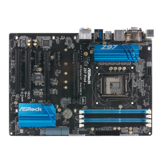
Seite 3: Motherboard-Layout
Z97 Pro4 Motherboard Layout ATX12V1 PWR_FAN1 CPU_FAN1 CPU_FAN2 USB 2.0 Top: T: USB2 RJ-45 B: USB3 Z97 Pro4 CHA_FAN2 PCI Express 3.0 Front USB 3.0 PCIE_PWR1 PCIE1 CMOS Battery NUT5 NUT4 NUT3 NUT2 NUT1 PCIE2 PCIE3 Intel PCIE4 PCI1 CHA_FAN1... - Seite 4 No. Description ATX 12V Power Connector (ATX12V1) Power Fan Connector (PWR_FAN1) CPU Fan Connector (CPU_FAN1) CPU Fan Connector (CPU_FAN2) 2 x 240-pin DDR3 DIMM Slots (DDR3_A1, DDR3_B1) 2 x 240-pin DDR3 DIMM Slots (DDR3_A2, DDR3_B2) ATX Power Connector (ATXPWR1) USB 3.0 Header (USB3_4_5) SATA3 Connector (SATA3_0) SATA3 Connector (SATA3_3) SATA3 Connector (SATA3_1)
- Seite 5 Z97 Pro4 I/O Panel No. Description No. Description USB 2.0 Ports (USB01) Microphone (Pink) D-Sub Port Optical SPDIF Out Port USB 3.0 Ports (USB3_0_1) USB 2.0 Ports (USB23) LAN RJ-45 Port* USB 3.0 Ports (USB3_2_3) Central / Bass (Orange) HDMI Port...
- Seite 6 * There are two LEDs on each LAN port. Please refer to the table below for the LAN port LED indications. ACT/LINK LED SPEED LED LAN Port Activity / Link LED Speed LED Status Description Status Description No Link 10Mbps connection Blinking Data Activity Orange...
-
Seite 7: Package Contents
If you require technical support related to this motherboard, please visit our website for specific information about the model you are using. You may find the latest VGA cards and CPU support list on ASRock’s website as well. ASRock website http://www.asrock.com. - Seite 8 (Socket 1150) • Digi Power design • 6 Power Phase design • Supports Intel® Turbo Boost 2.0 Technology • Supports Intel® K-Series unlocked CPUs • Supports ASRock BCLK Full-range Overclocking • Intel® Z97 Chipset • Dual Channel DDR3 Memory Technology Memory • 4 x DDR3 DIMM Slots...
- Seite 9 • 7.1 CH HD Audio with Content Protection (Realtek ALC892 Audio Audio Codec) • Premium Blu-ray Audio support • Supports Surge Protection (ASRock Full Spike Protection) • Nichicon Fine Gold Series Audio Caps • Gigabit LAN 10/100/1000 Mb/s • Giga PHY Intel® I218V • Supports Intel®...
- Seite 10 • 1 x DVI-D Port • 1 x HDMI Port • 1 x Optical SPDIF Out Port • 4 x USB 2.0 Ports (Supports ESD Protection (ASRock Full Spike Protection)) • 4 x USB 3.0 Ports (Supports ESD Protection (ASRock Full Spike Protection)) • 1 x RJ-45 LAN Port with LED (ACT/LINK LED and SPEED...
- Seite 11 Due to limitation, the actual memory size may be less than 4GB for the reservation for system usage under Windows® 32-bit operating systems. Windows® 64-bit operat- ing systems do not have such limitations. You can use ASRock XFast RAM to utilize the memory that Windows® cannot use.
-
Seite 12: Unique Features
ASRock Cloud ASRock partners with Kloudian to make your mobile devices connect to your PC seamlessly! ASRock Cloud allows you to get connected with your PC’s files, music, photos, and video clips remotely with tablets anytime, anywhere. -
Seite 13: Asrock My Favorites In Uefi
ASRock APP Charger Simply by installing the ASRock APP Charger makes your iPhone/iPad/iPod Touch charge up to 40% faster than before on your computer. ASRock APP Charger allows you to quickly charge many Apple devices simultaneously and even supports continuous charging when your PC enters into Standby mode (S1), Suspend to RAM (S3), hibernation mode (S4) or power off (S5). - Seite 14 UEFI easily. ASRock Instant Flash ASRock Instant Flash is a BIOS flash utility embedded in Flash ROM. This conve- nient BIOS update tool allows you to update the system BIOS in a few clicks without preparing an additional floppy diskette or other complicated flash utility. Just save the new BIOS file to your USB storage and launch this tool by pressing <F6>...
- Seite 15 S4/S5 state. ASRock Easy RAID Installer ASRock Easy RAID Installer can help you to copy the RAID driver from the support CD to your USB storage device. After copying the RAID driver to your USB storage device, please change “SATA Mode”...
- Seite 16 Chapter 2 Installation This is an ATX form factor motherboard. Before you install the motherboard, study the configuration of your chassis to ensure that the motherboard fits into it. Pre-installation Precautions Take note of the following precautions before you install motherboard components or change any motherboard settings.
-
Seite 17: Installing The Cpu
Z97 Pro4 2.1 Installing the CPU 1. Before you insert the 1150-Pin CPU into the socket, please check if the PnP cap is on the socket, if the CPU surface is unclean, or if there are any bent pins in the socket. - Seite 19 Z97 Pro4 Please save and replace the cover if the processor is removed. The cover must be placed if you wish to return the motherboard for after service.
- Seite 20 2.2 Installing the CPU Fan and Heatsink...
- Seite 21 Z97 Pro4 2.3 Installing Memory Modules (DIMM) This motherboard provides four 240-pin DDR3 (Double Data Rate 3) DIMM slots, and supports Dual Channel Memory Technology. 1. For dual channel configuration, you always need to install identical (the same brand, speed, size and chip-type) DDR3 DIMM pairs.
- Seite 23 Z97 Pro4 2.4 Expansion Slots (PCI and PCI Express Slots) There are 2 PCI slots and 4 PCI Express slots on the motherboard. Before installing an expansion card, please make sure that the power supply is switched off or the power cord is unplugged. Please read the documentation of the expansion card and make necessary hardware settings for the card before you start the installation.
- Seite 24 2.5 Jumpers Setup The illustration shows how jumpers are setup. When the jumper cap is placed on the pins, the jumper is “Short”. If no jumper cap is placed on the pins, the jumper is “Open”. The illustration shows a 3-pin jumper whose pin1 and pin2 are “Short” when a jumper cap is placed on these 2 pins.
- Seite 25 Z97 Pro4 2.6 Onboard Headers and Connectors Onboard headers and connectors are NOT jumpers. Do NOT place jumper caps over these headers and connectors. Placing jumper caps over the headers and connectors will cause permanent damage to the motherboard. PLED+...
- Seite 26 Power LED Header Please connect the chassis PLED- (3-pin PLED1) power LED to this header PLED+ PLED+ (see p.1, No. 17) to indicate the system’s power status. Serial ATA3 Connectors These six SATA3 (SATA3_0: connectors support SATA see p.1, No. 9) data cables for internal (SATA3_1: storage devices with up to...
- Seite 27 Z97 Pro4 USB 3.0 Header Besides four USB 3.0 Vbus Vbus Vbus IntA_PB_SSRX- (19-pin USB3_4_5) ports on the I/O panel, IntA_PB_SSRX+ IntA_PA_SSRX- IntA_PA_SSRX+ (see p.1, No. 8) there is one header on this IntA_PB_SSTX- IntA_PA_SSTX- IntA_PB_SSTX+ motherboard. Each USB IntA_PA_SSTX+ IntA_PB_D- 3.0 header can support...
- Seite 28 (3-pin PWR_FAN1) (see p.1, No. 2) CPU Fan Connectors This motherboard pro- (4-pin CPU_FAN1) vides a 4-Pin CPU fan GN D (see p.1, No. 3) (Quiet Fan) connector. + 12V CPU_ FAN_SPEED FAN_SPEED_CONTROL If you plan to connect a (3-pin CPU_FAN2) 3-Pin CPU fan, please (see p.1, No.
- Seite 29 Z97 Pro4 Serial Port Header RRXD1 This COM1 header DDTR#1 DDSR#1 (9-pin COM1) supports a serial port CCTS#1 (see p.1, No. 25) module. RRI#1 RRTS#1 TTXD1 DDCD#1 Chassis Intrusion Header This motherboard (2-pin CI1) supports CASE OPEN (see p.1, No. 24)
- Seite 30 2.7 M.2_SSD (NGFF) Module Installation Guide The M.2, also known as the Next Generation Form Factor (NGFF), is a small size and versatile card edge connector that aims to replace mPCIe and mSATA. The M.2_SSD (NGFF) Socket 3 can accommodate either a M.2 SATA3 6.0 Gb/s module or a M.2 PCI Express module up to Gen 2 x2 (10 Gb/s).
- Seite 31 Z97 Pro4 Step 3 Move the standoff based on the module type and length. The standoff is placed at the nut location D by default. Skip Step 3 and 4 and go straight to Step 5 if you are going to use the default nut.
- Seite 32 Plextor PX-AG256M6e ADATA AXNS381E-128GM-B Plextor PX-AG512M6e ADATA AXNS381E-256GM-B SanDisk SD6PP4M-128G Crucial CT120M500SSD4/120G SanDisk SD6PP4M-256G Crucial CT240M500SSD4/240G Samsung XP941-512G (MZHPU512HCGL) Intel SSDSCKGW080A401/80G Kingston RBU-SNS8400S3/180GD For the latest updates of M.2_SSD (NFGG) module support list, please visit our website for details: http://www.asrock.com...
-
Seite 33: Einleitung
Z97 Pro4 1 Einleitung Vielen Dank, dass Sie sich für das Z97 Pro4 von ASRock entschieden haben – ein zuverlässiges Motherboard, das konsequent unter der strengen Qualitätskontrolle von ASRock hergestellt wurde. Es liefert ausgezeichnete Leistung mit robustem Design, das ASRocks Streben nach Qualität und Beständigkeit erfüllt. -
Seite 34: Technische Daten
& 5 Generation • Digipower-Design • 6-Leistungsphasendesign • Unterstützt Intel® Turbo Boost 2.0-Technologie • Unterstützt CPUs mit freiem Multiplikator der Intel® K-Serie • Unterstützt ASRock BCLK-Übertaktung (voller Bereich) • Intel® Z97 Chipsatz • Dualkanal-DDR3-Speichertechnologie Speicher • 4 x DDR3-DIMM-Steckplätze • Unterstützt DDR3 2933+(OC)/2800(OC)/2400(OC)/2133... - Seite 35 DVI-D- und HDMI-Ports • 7.1-Kanal-HD-Audio mit Inhaltsschutz (Realtek ALC892- Audio Audiocodec) • Erstklassige Blu-ray-Audiounterstützung • Unterstützt Überspannungsschutz (ASRock Full Spike Protection) • Nichicon-Audiokappen der Fine Gold-Serie • Gigabit LAN 10/100/1000 Mb/s • Giga PHY Intel® I218V • Unterstützt Intel® Remote Wake Technology • Unterstützt Wake-On-LAN...
-
Seite 36: Anschluss
• 1 x HDMI-Port • 1 x Optischer SPDIF-Ausgang • 4 x USB 2.0-Ports (unterstützt Schutz gegen elektrostatische Entladung (ASRock Full Spike Protection)) • 4 x USB 3.0-Ports (unterstützt Schutz gegen elektrostatische Entladung (ASRock Full Spike Protection)) • 1 x RJ-45-LAN-Port mit LED (Aktivität/Verbindung-LED und Geschwindigkeit-LED) • HD-Audioanschlüsse: Hintere Lautsprecher / Zentral / Bass... -
Seite 37: Hardware-Überwachung
Aufgrund von Beschränkungen kann die Größe des tatsächlich für die Systemnutzung reservierten Speichers unter Windows®-Betriebssystemen mit 32 Bit weniger als 4 GB betragen. Windows®-Betriebssysteme mit 64 Bit haben keine derartigen Beschränkungen. Mit ASRock XFast RAM können Sie den Speicher einsetzen, den Windows® nicht nutzen kann. -
Seite 38: Jumpereinstellung
1.3 Jumpereinstellung Die Abbildung zeigt, wie die Jumper eingestellt werden. Wenn die Jumper-Kappe auf den Kontakten angebracht ist, ist der Jumper „kurzgeschlossen“. Wenn keine Jumper- Kappe auf den Kontakten angebracht ist, ist der Jumper „offen“. Die Abbildung zeigt einen 3-poligen Jumper, dessen Kontakt 1 und Kontakt 2 „kurzgeschlossen“ sind, wenn eine Jumper-Kappe auf diesen 2 Kontakten angebracht ist. -
Seite 39: Integrierte Stiftleisten Und Anschlüsse
Z97 Pro4 1.4 Integrierte Stiftleisten und Anschlüsse Integrierte Stiftleisten und Anschlüsse sind KEINE Jumper. Bringen Sie KEINE Jumper- Kappen an diesen Stiftleisten und Anschlüssen an. Durch Anbringen von Jumper-Kappen an diesen Stiftleisten und Anschlüssen können Sie das Motherboard dauerhaft beschädi- gen. - Seite 40 Betrieb-LED-Stiftleiste Bitte verbinden Sie die (3-polig, PLED1) Betrieb-LED des Gehäuses PLED- PLED+ (siehe S. 1, Nr. 17) zur Anzeige des System- PLED+ betriebsstatus mit dieser Stiftleiste. Serial-ATA-III-Anschlüsse Diese sechs SATA-III- (SATA3_0: Anschlüsse unterstützen siehe S. 1, Nr. 9) SATA-Datenkabel für (SATA3_1: interne Speichergeräte mit siehe S.
- Seite 41 Z97 Pro4 USB 3.0-Stiftleiste Neben vier USB 3.0-Ports Vbus Vbus Vbus IntA_PB_SSRX- (19-polig, USB3_4_5) an der E/A-Blende befindet IntA_PA_SSRX- IntA_PB_SSRX+ (siehe S. 1, Nr. 8) sich eine Stiftleiste an IntA_PA_SSRX+ IntA_PB_SSTX- diesem Motherboard. Jede IntA_PA_SSTX- IntA_PB_SSTX+ IntA_PA_SSTX+ USB 3.0-Stiftleiste kann IntA_PB_D- zwei Ports unterstützen.
- Seite 42 (3-polig, PWR_FAN1) (siehe S. 1, Nr. 2) CPU-Lüfteranschlüsse Dieses Motherboard bietet 4 3 2 1 (4-polig, CPU_FAN1) einen 4-poligen CPU- (siehe S. 1, Nr. 3) Lüfteranschluss (lautloser Lüfter). Falls Sie einen +12V FAN_SPEED 3-poligen CPU-Lüfter FAN_SPEED_CONTROL (3-polig, CPU_FAN2) anschließen möchten, (siehe S.
- Seite 43 Z97 Pro4 RRXD1 Serieller-Port-Stiftleiste Diese COM1-Stiftleiste DDTR#1 DDSR#1 (9-polig, COM1) unterstützt ein Modul für CCTS#1 (siehe S. 1, Nr. 25) serielle Ports. RRI#1 RRTS#1 TTXD1 DDCD#1 Gehäuseeingriff-Stiftleiste Dieses Motherboard (2-polig, CI1) unterstützt die Gehäuse- Signal (siehe S. 1, Nr. 24)
-
Seite 44: Contenu De L'emballage
à modification sans préavis. En cas de modifications du présent document, la version mise à jour sera disponible sur le site Internet ASRock sans notifica- tion préalable. Si vous avez besoin d’une assistance technique pour votre carte mère, veuillez visiter notre site Internet pour plus de détails sur le modèle que vous utilisez. - Seite 45 • Prend en charge la technologie Intel® Turbo Boost 2.0 • Prend en charge les processeurs débloqués de la série K Intel® • Prend en charge l’ o verclocking ASRock BCLK Full-range • Intel® Z97 Chipset • Technologie mémoire double canal DDR3 Mémoire...
- Seite 46 • Prend en charge la technologie Intel® Remote Wake • Prend en charge la fonction Wake-On-LAN • Protection contre les orages/décharges électrostatiques (Protection complète contre les pics ASRock) • Prend en charge la fonction d’ é conomie d’ é nergie Ethernet 802.3az...
- Seite 47 • 1 x port sortie optique SPDIF • 4 x ports USB 2.0 (Protection contre les décharges élec- trostatiques (Protection complète contre les pics ASRock)) • 4 x ports USB 3.0 (Protection contre les décharges élec- trostatiques (Protection complète contre les pics ASRock)) • 1 x port RJ-45 LAN avec LED (LED ACT/LIEN et LED...
-
Seite 48: Système D'exploitation
Certifications • ErP/EuP Ready (alimentation ErP/EuP ready requise) * pour des informations détaillées de nos produits, veuillez visiter notre site : http://www.asrock.com Il est important de signaler que l'overcloking présente certains risques, incluant des modifi- cations du BIOS, l’ a pplication d’une technologie d’ o verclocking déliée et l'utilisation d'outils d'overclocking développés par des tiers. - Seite 49 Z97 Pro4 1.3 Configuration des cavaliers (jumpers) L’illustration ci-dessous vous renseigne sur la configuration des cavaliers (jumpers). Lorsque le capuchon du cavalier est installé sur les broches, le cavalier est « court- circuité ». Si le capuchon du cavalier n’ e st pas installé sur les broches, le cavalier est « ouvert ».
- Seite 50 1.4 Embases et connecteurs de la carte mère Les embases et connecteurs situés sur la carte NE SONT PAS des cavaliers. Ne placez JAMAIS de capuchons de cavaliers sur ces embases ou connecteurs. Placer un capuchon de cavalier sur ces embases ou connecteurs endommagera irrémédiablement votre carte mère. Embase du panneau sys- Branchez le bouton de PLED+...
- Seite 51 Z97 Pro4 Embase LED Veuillez brancher le LED d’alimentation d’alimentation du châssis PLED- PLED+ (PLED1 à 3 broches) sur cette embase pour in- PLED+ (voir p.1, No. 17) diquer l’ é tat d’alimentation du système. Connecteurs Serial ATA3 Ces six connecteurs...
- Seite 52 Embases USB 3.0 En plus des quatre ports Vbus Vbus Vbus IntA_PB_SSRX- (USB3_4_5 à 19 broches) USB 3.0 sur le panneau IntA_PA_SSRX- IntA_PB_SSRX+ (voir p.1, No. 8) E/S, cette carte mère IntA_PA_SSRX+ IntA_PB_SSTX- est dotée d’une embase IntA_PA_SSTX- IntA_PB_SSTX+ IntA_PA_SSTX+ supplémentaire.
- Seite 53 Z97 Pro4 (PWR_FAN1 à 3 broches) (voir p.1, No. 2) Connecteurs du Cette carte mère est dotée 4 3 2 1 ventilateur du processeur d’un connecteur pour (CPU_FAN1 à 4 broches) ventilateur de processeur (voir p.1, No. 3) (Quiet Fan) à 4 broches.
- Seite 54 Embase pour port série Cette embase COM1 prend RRXD1 DDTR#1 (COM1 à 9 broches) en charge un module de DDSR#1 CCTS#1 (voir p.1, No. 25) port série. RRI#1 RRTS#1 TTXD1 DDCD#1 Embase d’intrusion châssis Cette carte mère prend (CI1 à 2 broches) en charge la fonction (voir p.1, No.
-
Seite 55: Contenuto Della Confezione
Nel caso di eventuali modifiche del presente manuale, la versione aggiornata sarà disponibile sul sito Web di ASRock senza ulteriore preavviso. Per il supporto tecnico correlato a questa scheda madre, visitare il nostro sito Web per informazioni specifiche relative al modello attualmente in uso. - Seite 56 • MOSFET NexFET • Cappucci di platino 12K (condensatori polimerici conduttivi d’alta qualità prodotti al 100% in Giappone) • PCB Sapphire Black Protezione completa ASRock dai picchi di corrente ASRock Cloud APP Shop ASRock • Supporta processori 4 Gen e 5 Generation Intel®...
- Seite 57 • LAN Gigabit 10/100/1000 Mb/s • Giga PHY Intel® I218V • Supporta la tecnologia Intel® Remote Wake • Supporta Wake-On-LAN • Supporto la protezione da fulmini/scariche elettrostatiche (ESD) (protezione completa ASRock dai picchi di corrente) • Supporta Energy Efficient Ethernet 802.3az • Supporta PXE...
- Seite 58 • 1 x porta HDMI • 1 x porta uscita SPDIF ottico • 4 x Porte USB 2.0 (supporto protezione da scariche elettrostat- iche (ESD) (protezione completa ASRock dai picchi di cor- rente)) • 4 x Porte USB 3.0 (supporto protezione da scariche elettrostat-...
- Seite 59 4 GB per riservare l'uso del sistema ai sistemi operativi di Windows® a 32 bit. I sistemi operativi Windows® a 64 bit non possiedono tali limitazioni. È possibile utilizzare la RAM XFast di ASRock per utilizzare la memoria che Windows® non può utilizzare.
- Seite 60 1.3 Impostazione jumper L'illustrazione mostra in che modo vengono impostati i jumper. Quando il cappuccio del jumper è posizionato sui pin, il jumper è "cortocircuitato". Se sui pin non è posizionato alcun cappuccio del jumper, il jumper è "aperto". L'illustrazione mostra un jumper a 3 pin i cui pin1 e pin2 sono "cortocircuitati"...
- Seite 61 Z97 Pro4 1.4 Header e connettori sulla scheda Gli header e i connettori sulla scheda NON sono jumper. NON posizionare cappucci del jumper su questi header e connettori. Il posizionamento di cappucci del jumper su header e connettori provocherà danni permanenti alla scheda madre.
- Seite 62 Header LED di Collegare il LED di alimentazione alimentazione chassis a PLED- PLED+ (PLED1 a 3 pin) questo header per indicare PLED+ (vedere pag. 1, n. 17) lo stato di alimentazione del sistema. Connettori Serial ATA3 Questi sei connettori (SATA3_0: SATA3 supportano cavi vedere pag.1, n.
- Seite 63 Z97 Pro4 Header USB 3.0 Oltre alle quattro porte Vbus Vbus Vbus IntA_PB_SSRX- (USB3_4_5 a 19 pin) USB 3.0 sul pannello I/O, IntA_PA_SSRX- IntA_PB_SSRX+ (vedere pag. 1, n. 8) su questa scheda madre IntA_PA_SSRX+ IntA_PB_SSTX- vi è un header. Ciascun...
- Seite 64 (PWR_FAN1 a 3 pin) (vedere pag. 1, n. 2) Connettori della ventola Questa scheda madre è 4 3 2 1 della CPU dotata di un connettore per (CPU_FAN1 a 4 pin) la ventola della CPU (Ven- (vedere pag. 1, n. 3) tola silenziosa) a 4 pin.
- Seite 65 Z97 Pro4 Header porta seriale Questo header COM1 RRXD1 DDTR#1 (COM1 a 9 pin) supporta un modulo di DDSR#1 CCTS#1 (vedere pag. 1, n. 25) porta seriale. RRI#1 RRTS#1 TTXD1 DDCD#1 Header di intrusione nello Questa scheda madre chassis supporta la funzionalità di...
-
Seite 66: Contenido Del Paquete
1 Introducción Gracias por comprar la placa base ASRock Z97 Pro4, una placa base fiable fabricada según el rigurosísimo control de calidad de ASRock. Ofrece un rendimiento excelente con un diseño resistente de acuerdo con el compromiso de calidad y resistencia de ASRock. - Seite 67 MOSFET • Tapas de platino de 12K (condensadores de polímero conductor de alta calidad, 100% fabricados en Japón) • PCB de zafiro negro Protección ASRock Full Spike ASRock Cloud Tienda de aplicaciones ASRock • Compatible con 4 generación de procesadores Intel® Core (Socket 1150) • Diseño Digi Power...
- Seite 68 • Compatible con la Tecnología Remote Wake de Intel® • Compatible con Wake-On-LAN • Compatible con protección contra rayos y electricidad elec- trostática (protección ASRock Full Spike) • Compatible con Ethernet de consumo eficiente de energía 802.3az • Compatible con PXE...
- Seite 69 • 1 puerto HDMI • 1 puerto de salida SPDIF óptica • 4 puertos USB 2.0 (compatible con protección contra electricidad estática (protección ASRock Full Spike)) • 4 puertos USB 3.0 (compatible con protección contra electricidad estática (protección ASRock Full Spike)) • 1 puerto LAN RJ-45 con LED (ACT/LINK LED y SPEED LED)
- Seite 70 ErP/EuP) * Para obtener más información acerca del producto, visite nuestro sitio web: http://www.asrock.com Tenga en cuenta que existen ciertos riesgos relacionados con el overclocking (sobreacel- eración), incluyendo el ajuste de la configuración del BIOS, aplicando la Tecnología overcloking no vinculada o utilizando las herramientas de overclocking de tercera parte.
- Seite 71 Z97 Pro4 1.3 Instalación de los puentes La instalación muestra cómo deben instalarse los puentes. Cuando la tapa de puente se coloca en los pines, el puente queda “Corto”. Si no coloca la tapa de puente en los pines, el puente queda “Abierto”. La ilustración muestra un puente de 3 pines cuyo pin 1 y pin 2 son “Cortos”...
- Seite 72 1.4 Conectores y cabezales incorporados Los cabezales y conectores incorporados NO son puentes. NO coloque tapas de puente so- bre estos cabezales y conectores. Si coloca tapas de puente sobre los cabezales y conectores dañará de forma permanente la placa base. Cabezal del panel del Conecte el interruptor de PLED+...
- Seite 73 Z97 Pro4 Cabezal de indicador LED Conecte el indicador LED de alimentación de alimentación del chasis PLED- PLED+ (PLED1 de 3 pines) a este cabezal para indicar PLED+ (consulte la pág.1, N.º 17) el estado de alimentación del sistema. Conectores Serie ATA3...
- Seite 74 Cabezal USB 3.0 Además de cuatro puertos Vbus Vbus Vbus IntA_PB_SSRX- (USB3_4_5 de 19 pines) USB 3.0 en el panel I/O, IntA_PA_SSRX- IntA_PB_SSRX+ (consulte la pág.1, N.º 8) esta placa base contiene un IntA_PA_SSRX+ IntA_PB_SSTX- cabezal. Cada cabezal USB IntA_PA_SSTX- IntA_PB_SSTX+ IntA_PA_SSTX+ 3.0 admite dos puertos.
- Seite 75 Z97 Pro4 (PWR_FAN1 de 3 pines) (consulte la pág.1, N.º 2) Conectores del ventilador Esta placa base contiene 4 3 2 1 de la CPU un conector de ventilador (CPU_FAN1 de 4 pines) (ventilador silencioso) de (consulte la pág.1, N.º 3) CPU de 4 pines.
- Seite 76 Cabezal de puerto serie Este cabezal COM1 admite RRXD1 DDTR#1 (COM1 de 9 pines) un módulo de puerto serie. DDSR#1 CCTS#1 (consulte la pág.1, N.º 25) RRI#1 RRTS#1 TTXD1 DDCD#1 Cabezal de intrusión de Esta placa base es chasis compatible con la Signal (CI1 de 2 pines) función de detección de...
-
Seite 77: Комплект Поставки
Z97 Pro4 1 Введение Благодарим вас за приобретение надежной системной платы ASRock Z97 Pro4, выпускаемой под постоянным жестким контролем качества компании ASRock. Эта материнская плата обеспечивает великолепную производительность и характеризуется прочной конструкцией в соответствии с требованиями компании ASRock в отношении качества и долговечности. - Seite 78 • Digi Power design • Система питания 6 • Поддержка технологии Intel® Turbo Boost 2.0 • Поддержка процессоров Intel® серии K с разблокированным множителем • Поддержка полного разгона процессора ASRock BCLK • Intel® Z97 Чипсет • Двухканальная память DDR3 Память...
- Seite 79 • 7.1-канальный звук высокой четкости HD Audio с Аудио защитой данных (аудиокодек Realtek ALC892) • Поддержка Premium Blu-ray Audio • Защита от перенапряжения (ASRock Full Spike Protection) • Конденсаторы для аудиосистем серии Nichicon Fine Gold • Gigabit LAN 10/100/1000 Мб/с...
- Seite 80 • 4 x Порт USB 2.0 с защитой от электростатического напряжения (ASRock Full Spike Protection) • 4 x Порт USB 3.0 с защитой от электростатического напряжения (ASRock Full Spike Protection) • 1 x RJ-45 для ЛВС с СИД (СИД ACT/LINK и МИД...
- Seite 81 ответственность за возможный ущерб, вызванный разгоном процессора. В связи с ограничением при работе под 32-разрядной ОС Windows® фактический объем памяти может быть меньше 4 Гбайт. Для 64-разрядных ОС Windows® таких ограничений нет. Для использования той памяти, которую ОС Windows® не может использовать, используйте ASRock XFast RAM.
- Seite 82 1.3 Установка перемычек Установка перемычек показана на рисунке. При установке колпачковой перемычки на контакты перемычка «замкнута». Если колпачковая перемычка на контакты не установлена, перемычка «разомкнута». На рисунке показана 3-контактная перемычка с замкнутыми контактами 1 и 2 при установке на них колпачковой...
- Seite 83 Z97 Pro4 1.4 Колодки и разъемы, расположенные на материнской плате Расположенные на материнской плате колодки и разъемы перемычками НЕ являются. НЕ устанавливайте на эти колодки и разъемы колпачковые перемычки. Установка колпачковых перемычек на эти колодки и разъемы может вызвать неустранимое повреждение материнской платы.
- Seite 84 Колодка светодиодного Подключите индикатора питания светодиодный индикатор PLED- PLED+ (3-контактная, PLED1) питания корпуса к PLED+ (См. стр. 1, № 17) этой колодке, чтобы обеспечить индикацию состояния питания системы. Разъемы Serial ATA3 Эти шесть (SATA3_0: разъемов SATA3 см. стр.1, № 9) предназначены...
- Seite 85 Z97 Pro4 Колодка USB 3.0 Кроме четырех портов Vbus Vbus (19-контактная, USB 3.0 на панели ввода- Vbus IntA_PB_SSRX- IntA_PB_SSRX+ IntA_PA_SSRX- USB3_4_5) вывода на материнской IntA_PA_SSRX+ (См. стр. 1, № 8) IntA_PB_SSTX- плате также есть IntA_PA_SSTX- IntA_PB_SSTX+ одна колодка. Каждая IntA_PA_SSTX+ IntA_PB_D- колодка...
- Seite 86 (3-контактный, PWR_FAN1) (См. стр. 1, № 2) Разъемы вентиляторов Эта материнская 4 3 2 1 ЦП плата снабжена (4-контактный, 4-контактным разъемом CPU_FAN1) для малошумящего +12V (См. стр. 1, № 3) вентилятора ЦП. Если вы FAN_SPEED FAN_SPEED_CONTROL собираетесь подключить (3-контактный, 3-контактный CPU_FAN2) вентилятор...
- Seite 87 Z97 Pro4 Колодка Колодка COM1 RRXD1 DDTR#1 последовательного порта поддерживает DDSR#1 CCTS#1 (9-контактная, COM1) подключение модуля (См. стр. 1, № 25) последовательного порта. RRI#1 RRTS#1 TTXD1 DDCD#1 Колодка для датчика Эта материнскаяплата вскрытия корпуса поддерживает (2-контактная, CI1) технологию определения Signal (См.
-
Seite 88: Conteúdo Da Embalagem
1 Introdução Obrigado por adquirir a placa mãe ASRock Z97 Pro4, uma confiável placa mãe ASRock produzida sob rigoroso controle de qualidade consistente. Esta placa principal oferece um excelente desempenho com um design robusto em conformidade com o compromisso da ASRock em fabricar produtos de qualidade e resistentes. -
Seite 89: Especificações
• Design com 6 fases de alimentação • Suporta a tecnologia Intel® Turbo Boost 2.0 • Suporta CPU desbloqueado da série K da Intel® • Suporta Overclocking total ASRock BCLK • Intel® Z97 Chipset • Tecnologia de memória DDR3 de dois canais Memória... - Seite 90 • Giga PHY Intel® I218V • Suporta tecnologia Intel® Remote Wake • Suporta Wake-On-LAN • Suporta Proteção contra Relâmpago/EDS (Proteção Total Contra Picos ASRock) • Suporta Energy Efficient Ethernet 802.3az • Suporta PXE • 1 x Porta PS/2 para mouse/teclado E/S do • 1 x Porta D-Sub...
- Seite 91 • 1 x Conector Thunderbolt AIC • 2 x Plataformas USB 2.0 (Suporta 4 portas USB 2.0) (Suporta Proteção ESD (Proteção Total Contra Picos ASRock)) • 1 x Plataforma USB 3.0 (Suporta 2 portas USB 3.0) (Suporta Proteção ESD (Proteção Total Contra Picos ASRock)) • 64Mb AMI Legal UEFI BIOS com suporte multilingue GUI...
- Seite 92 * Para obter informações detalhadas sobre o produto, por favor, visite o nosso site: http://www.asrock.com Por favor, observe que existe um certo risco envolvendo overclocking, incluindo o ajuste das definições na BIOS, a aplicação de tecnologia Untied Overclocking ou a utilização de ferramentas de overclocking de terceiros.
- Seite 93 Z97 Pro4 1.3 Configuração dos jumpers A imagem abaixo mostra como os jumpers são configurados. Quando a tampa do jumper é colocada nos pinos, o jumper é "Curto". Se não for colocada uma tampa de jumper nos pinos, o jumper é "Aberto". A imagem mostra um jumper de 3 pinos cujos pino1 e pino2 estão "Curtos"...
- Seite 94 1.4 Suportes e conectores onboard Os conectores e suportes onboard NÃO são jumpers. NÃO coloque tampas de jumpers sobre estes terminais e conectores. Colocar tampas de jumpers sobre os terminais e conec- tores irá causar danos permanentes à placa-mãe. Suporte do painel de Ligue o botão de PLED+ PLED-...
- Seite 95 Z97 Pro4 Suporte LED de Por favor, conecte o LED alimentação de alimentação do chassi PLED- PLED+ (PLED1 de 3 pinos) neste suporte para indicar PLED+ (ver p.1, N.º 17) o estado de alimentação do sistema. Conectores série ATA3 Estes seis conectores...
- Seite 96 Suporte USB 3.0 Além das quatro portas Vbus Vbus Vbus IntA_PB_SSRX- (USB3_4_5 de 19 pinos) USB 3.0 no painel de E/ IntA_PA_SSRX- IntA_PB_SSRX+ IntA_PA_SSRX+ (ver p.1, N.º 8) S, existe um suporte nesta IntA_PB_SSTX- IntA_PA_SSTX- IntA_PB_SSTX+ placa principal. Cada IntA_PA_SSTX+ suporte USB 3.0 pode IntA_PB_D- IntA_PA_D-...
- Seite 97 Z97 Pro4 (PWR_FAN1 de 3 pinos) (ver p.1, N.º 2) FAN_VOLTAGE FAN_SPEED Conectores do ventilador Esta placa mãe inclui um 4 3 2 1 da CPU conector de ventilador (CPU_FAN1 de 4 pinos) da CPU (Ventilador +12V (ver p.1, N.º 3) silencioso) de 4 pinos.
- Seite 98 Suporte da porta serial Este suporte COM1 recebe RRXD1 DDTR#1 (COM1 de 9 pinos) DDSR#1 um módulo da porta serial. CCTS#1 (ver p.1, N.º 25) RRI#1 RRTS#1 TTXD1 DDCD#1 Suporte de intrusão do Esta placa-mãe suporta chassi a função de detecção de (CI1 de 2 pinos) ABERTURA da CAIXA Signal...
-
Seite 99: Ambalaj İçeriği
Z97 Pro4 1 Giriş ASRock'ın zorlu kalite kontrol süreçlerinden geçmiş olan ASRock Z97 Pro4 anakartını satın aldığınız için teşekkür ederiz. Sağlam tasarımı ile ASRock'ın kalite ve dayanıklılık taahhüdüne uygun şekilde mükemmel performans sağlar. Anakart özellikleri ve BIOS yazılımı güncellenebileceğinden, bu kılavuzun içeriği herhangi bir bildirimde bulunulmaksızın değiştirilebilir. - Seite 100 • Dijital Güç tasarımı • 6 Güç Safhası tasarımı • Intel® Turbo Boost 2.0 Teknolojisini destekler • Intel® K Serisi kilitsiz işlemcileri destekler • ASRock BCLK tam aralıklı Hız Aşırtmayı destekler Yonga • Intel® Z97 kümesi • Çift Kanallı DDR3 Bellek Teknolojisi Bellek • 4 x DDR3 DIMM Yuvası...
- Seite 101 • İçerik Koruma Özelliği ile 7.1 CH HD Ses (Realtek ALC892 Ses Codec Bileşeni) • Üstün Blu-ray Ses desteği • Dalgalanma Koruması Destekler (ASRock Tam Ani Gerilim Koruması) • Nichicon Fine Gold Serisi Ses Kapakları • Gigabit LAN 10/100/1000 Mb/s • Giga PHY Intel®...
-
Seite 102: Arka Panel
• 1 x Ön Panel Ses Bağlayıcısı • 1 x Thunderbolt AIC Bağlayıcısı • 2 x USB 2.0 Bağlantısı (4 USB 2.0 bağlantı noktası destekler) (ESD Koruması Destekler (ASRock Tam Ani Gerilim Koruması)) • 1 x USB 3.0 Bağlantısı (2 USB 3.0 bağlantı noktası destekler) (ESD Koruması... - Seite 103 • ErP/EuP için hazır (ErP/EuP için hazır güç beslemesi gerek- lidir) * Detaylı ürün bilgisi için, lütfen web sitemizi ziyaret edin: http://www.asrock.com Lütfen, BIOS ayarlarını düzenleme, Bağımsız Hız Aşırtma Teknolojinin uygulanması ya da üçüncü kişilerin hız aşırtma araçlarının kullanılması da dahil olmak üzere tüm hız aşırtma işlemlerinin belirli bir risk taşıdığını...
- Seite 104 1.3 Bağlantı Teli Kurulumu Çizim, bağlantı tellerinin kurulumunu göstermektedir. Tel kapağı, pimlerin üzerine yerleştirildiğinde, tel "Kısa" olur. Pimlerin üzerinde tel kapağı bulunmadığında, tel "Açık" olur. Çizim, pin1 ve pin2 alanları "Kısa" olan ve bu iki pim üzerinde bir bağlantı teli kapağı bulunan 3-pin bağlantı telini göstermektedir. CMOS'u Temizle Bağlantı...
- Seite 105 Z97 Pro4 1.4 Ekli Bağlantılar ve Bağlayıcılar Ekli bağlantılar ve bağlayıcılar bağlantı teli değildir. Bağlantı teli kapaklarını bu bağlantı ve bağlayıcılar üzerine yerleştirmeyin. Bağlantı teli kapaklarının bağlantılar ile bağlayıcılar üzerine yerleştirilmesi, anakarta kalıcı hasar verebilir. Sistem Paneli Bağlantısı Güç anahtarını bağlayın,...
- Seite 106 Güç LED Bağlantısı Sistemin güç durumunun (3-pin PLED1) belirtilmesi için lütfen PLED- PLED+ PLED+ (bkz. sf.1, No. 17) güç LED'ini bu bağlantıya takın. Seri ATA3 Bağlayıcıları Bu altı SATA3 bağlayıcısı, (SATA3_0: veri aktarım hızı 6,0 Gb/ bkz. sf.1, No. 9) sn'ye kadar olan dahili (SATA3_1: depolama aygıtları...
- Seite 107 Z97 Pro4 USB 3.0 Bağlantı Bu anakart üzerinde, I/O Vbus Vbus Vbus IntA_PB_SSRX- (19-pin USB3_4_5) paneli üzerindeki dört USB IntA_PA_SSRX- IntA_PB_SSRX+ IntA_PA_SSRX+ (bkz. sf.1, No. 8) 3.0 bağlantı noktasının IntA_PB_SSTX- IntA_PA_SSTX- IntA_PB_SSTX+ yanı sıra, bir adet bağlantı IntA_PA_SSTX+ IntA_PB_D- bulunmaktadır. Her...
- Seite 108 (3-pin PWR_FAN1) (bkz sf.1, No. 2) CPU Fan Bağlayıcıları Bu anakart, 4-Pin CPU 4 3 2 1 (4-pin CPU_FAN1) fan (Sessiz Fan) bağlayıcısı (bkz sf.1, No. 3) sağlamaktadır. 3-Pin CPU +12V fan bağlamak istiyorsanız, FAN_SPEED FAN_SPEED_CONTROL (3-pin CPU_FAN2) lütfen Pin 1-3'ü kullanın. (bkz sf.1, No.
- Seite 109 Z97 Pro4 Seri Bağlantı Noktası Bu COM1 bağlantısı seri RRXD1 DDTR#1 DDSR#1 Bağlantısı bağlantı yuvası modülünü CCTS#1 (9-pin COM1) destekler. (bkz. sf.1, No. 25) RRI#1 RRTS#1 TTXD1 DDCD#1 Kasa Yetkisiz Erişim Bu anakartın kasa Bağlantısı kapağının açılıp (2-pin CI1) açılmadığını tespit eden Signal (bkz.
- Seite 110 1 개요 ASRock Z97 Pro4 마더보드를 구입해 주셔서 감사합니다 . 이 마더보드는 ASRock 의 일관되고 엄격한 품질관리 하에 생산되어 신뢰성이 우수합니다 . 품질과 내 구성에 대한 ASRock 의 기준에 부합하는 우수한 성능과 견고한 설계를 제공합 니다 . 마더보드 규격과 BIOS 소프트웨어를 업데이트할 수도 있기 때문에 , 이 설명서의...
- Seite 111 • Digi 전원 구조 • 6 개 전원 위상 구조 • Intel® Turbo Boost 2.0 기술 지원 • Intel®K- 시리즈 잠금 해제 CPU 지원 • ASRock BCLK 전범위 오버클로킹 지원 • Intel® Z97 칩세트 • 듀얼 채널 DDR3 메모리 기술...
- Seite 112 • Nichicon Fine Gold 시리즈 오디오 캡 • Gigabit LAN 10/100/1000 Mb/s • Giga PHY Intel® I218V • Intel® 리모트 웨이크 기술 지원 • Wake-On-LAN 지원 • 번개 /ESD 보호 지원 (ASRock 풀 스파이크 보호 ) • 절전형 이더넷 802.3az 지원 • PXE 지원...
- Seite 113 • HDMI 포트 1 개 • 광학 SPDIF 출력 포트 1 개 • USB 2.0 포트 4 개 (ESD 보호 지원 (ASRock 풀 스파이크 보 호 )) • USB 3.0 포트 4 개 (ESD 보호 지원 (ASRock 풀 스파이크 보...
- Seite 114 제한 때문에 실제 메모리 크기는 Windows® 32 비트 운영체제 하의 시스템 사용 을 위한 예비 메모리용 4GB 보다 더 적을 수 있습니다 . Windows® 64 비트 운영체 제에는 그러한 제한이 없습니다 . ASRock XFast RAM 을 사용하여 Windows® 가 사용할 수 없는 메모리를 이용할 수 있습니다 .
- Seite 115 Z97 Pro4 1.3 점퍼 설정 그림은 점퍼를 어떻게 설정하는지 보여줍니다 . 점퍼 캡을 핀에 씌우면 점퍼가 “단락”됩니다 . 점퍼 캡을 핀에 씌우지 않으면 점퍼가 “단선”됩니다 . 그림 은 3 핀 점퍼를 보여주며 핀 1 과 핀 2 는 점퍼 캡을 씌울 때 “단락”됩니다 .
- Seite 116 1.4 온보드 헤더 및 커넥터 온보드 헤더와 커넥터는 점퍼가 아닙니다 . 점퍼 캡을 온보드 헤더와 커넥터에 씌 우지 마십시오 . 점퍼 캡을 온보드 헤더와 커넥터에 씌우면 마더보드가 영구적으 로 손상됩니다 . 시스템 패널 헤더 섀시의 전원 스위치 , PLED+ PLED- PWRBTN# (9 핀...
- Seite 117 Z97 Pro4 전원 LED 헤더 시스템 전원 상태를 나 (3 핀 PLED1) 타내려면 섀시 전원 PLED- PLED+ PLED+ (1 페이지 , 17 번 항목 참조 ) LED 를 이 헤더에 연 결하십시오 . 시리얼 ATA3 커넥터 이들 6 개의 SATA3 커...
- Seite 118 USB 3.0 헤더 I/O 패널에 USB 3.0 포 Vbus Vbus Vbus IntA_PB_SSRX- (19 핀 USB3_4_5) 트 네 개가 탑재되어 IntA_PA_SSRX- IntA_PB_SSRX+ IntA_PA_SSRX+ (1 페이지 , 8 번 항목 참조 ) 있을 뿐 아니라 마더 IntA_PB_SSTX- IntA_PA_SSTX- IntA_PB_SSTX+ 보드에 헤더 한 개가 IntA_PA_SSTX+ IntA_PB_D- 탑재되어...
- Seite 119 Z97 Pro4 (3 핀 PWR_FAN1) (1 페이지 , 2 번 항목 참조 ) CPU 팬 커넥터 이 마더보드에는 4 핀 4 3 2 1 (4 핀 CPU_FAN1) CPU 팬 ( 저소음 팬 ) (1 페이지 , 3 번 항목 참조 ) 커넥터가...
- Seite 120 시리얼 포트 헤더 이 COM1 헤더는 시 RRXD1 DDTR#1 DDSR#1 (9 핀 COM1) 리얼 포트 모듈을 지 CCTS#1 (1 페이지 , 25 번 항목 참조 ) 원합니다 . RRI#1 RRTS#1 TTXD1 DDCD#1 섀시 침입 헤더 이 마더보드는 섀시 (2 핀 CI1) 커버가...
- Seite 121 Z97 Pro4 1 はじめに ASRock Z97 Pro4 マザーボードをお買い上げいただきまして誠にありがとう ござ います。 ASRock Z97 Pro4 マザーボードは、 ASRock の一貫した厳格な品質管理の 下で製造された信頼性の高いマザーボードです。 アスロックの品質と耐久性の取 り組みに準拠した堅牢な設計を持つ、 優れたパフォーマンスを提供します。 マザーボードの仕様と BIOS ソフトウェアは更新されるこ とがあるため、 このマニュ アルの内容は予告なしに変更するこ とがあります。 このマニュアルの内容に変更が あった場合には、 更新されたバージョンは、 予告なく アスロックのウェブサイ トから 入手できるようになります。 このマザーボードに関する技術的なサポートが必要な 場合には、 ご使用のモデルについての詳細情報を、 当社のウェブサイ トで参照く だ...
- Seite 122 MOSFET • 12K プラチナコンデンサ (100% 日本製の高品質導電 性ポリマコンデンサ) • サファイアブラック PCB ASRock 完全スパイク保護 ASRock Cloud ASRock APP ショ ップ • 第 4 世代および第 5 世代 Intel® Core プロセッサーに 対応 (ソケッ ト 1150) • デジタル電源設計 • 6 電源フェーズ設計 • Intel® ターボブースト 2.0 テク ノロジーをサポート...
- Seite 123 • サージ保護に対応 (ASRock 完全スパイク保護) • ニチコン製ファインゴールドシリーズオーディオコンデ ンサ • ギガビッ ト LAN 10/100/1000 Mb/ 秒 • ギガ PHY Intel® I218V • Intel® リモートウェイクテク ノロジーをサポート • ウェイクオンランをサポート • 雷 / 静電気放電 (ESD) 保護に対応 (ASRock 完全スパ イク保護) • エネルギー効率のよいイーサネッ ト 802.3az をサポー ト • PXE をサポート...
- Seite 124 • 1 x Thunderbolt AIC コネクタ • 2 x USB 2.0 ヘッダー (4 個の USB 2.0 ポートに対応) ( 静 電気放電 (ESD) 保護に対応 (ASRock 完全スパイク保護) ) • 1 x USB 3.0 ヘッダー (2 個の USB 3.0 ポートに対応) ( 静 電気放電 (ESD) 保護に対応 (ASRock 完全スパイク保護) )...
- Seite 125 64-bit / 7 32-bit / 7 64-bit 認証 • FCC、 CE、 WHQL • ErP/EuP Ready ( ErP/EuP 対応) ( ErP/EuP 対応電源供給 装置が必要です) * 商品詳細については、 当社ウェブサイ トをご覧く ださい。 http://www.asrock.com BIOS 設定の調整、 アンタイ ドオーバークロックテク ノロジーの適用、 サードパーティ のオーバークロックツールの使用などを含む、 オーバークロックには、 一定のリスク を伴いますのでご注意く ださい。 オーバークロックするとシステムが不安定になった り、 システムのコンポーネントやデバイスが破損するこ とがあります。 ご自分の責任...
- Seite 126 1.3 ジャンパー設定 このイラストは、 ジャンパーの設定方法を示しています。 ジャンパーキャップがピ ンに被さっていると、 ジャンパーは 「ショート」 です。 ジャンパーキャップがピンに被 さっていない場合には、 ジャンパーは 「オープン」 です。 この図は 3 ピンのジャンパー を表し、 ジャンパーキャップがピン 1 とピン 2 に被さっているとき、 これらのピンは 「ショート」 です。 CMOS クリアジャンパー (CLRCMOS1) (p.1、 No. 23 参照) デフォルト CMOS の ク リア CLRCMOS1 は、 CMOS のデータをク リアするこ とができます。 ク リアして、 デフォ ルト設定にシステムパラメーターをリセッ...
- Seite 127 Z97 Pro4 1.4 オンボードのヘッダーとコネクター オンボードヘッダーとコネクターはジャンパーではありません。 これらヘッダーとコ ネクターにはジャンパーキャップを被せないでく ださい。 ヘッダーおよびコネクター にジャンパーキャップを被せると、 マザーボードに永久損傷が起こるこ とがあります。 システムパネルヘッダー 電源スイッチを接続し、 PLED+ PLED- (9 ピンパネル 1) スイッチをリセッ トし、 下 PWRBTN# (p.1、 No. 18 参照) 記のピン割り当てに従っ て、 シャーシのシステムス RESET# テータス表示ランプをこ HDLED- のヘッダーにセッ トしま HDLED+ す。 ケーブルを接続すると きには、 ピンの+と−に...
- Seite 128 電源 LED ヘッダー システムの電源ステー (3 ピン PLED1) タスを表示するために、 PLED- PLED+ (p.1、 No. 17 参照) PLED+ シャーシ電源 LED をこの ヘッダーに接続してく だ さい。 シリアル ATA3 これら 6 つの SATA3 コネ コネクター クターは、 最高 6.0 Gb/ 秒 (SATA3_0 : のデータ転送速度で内部 p.1、 No. 9 参照) ストレージデバイス用の...
- Seite 129 Z97 Pro4 USB 3.0 ヘッダー I/O パネルの 4 つの USB Vbus Vbus Vbus IntA_PB_SSRX- (19 ピン USB3_4_5) 3.0 ポートに加えて、 この IntA_PA_SSRX- IntA_PB_SSRX+ IntA_PA_SSRX+ (p.1、 No. 8 参照) マザーボードには 1 つの IntA_PB_SSTX- IntA_PA_SSTX- IntA_PB_SSTX+ ヘッダーがあります。 各 IntA_PA_SSTX+ IntA_PB_D- USB 3.0 ヘッダーは、 2 つ...
- Seite 130 (3 ピン PWR_FAN1) (p.1、 No. 2 参照) CPU ファンコネクター このマザーボードは 4 ピ 4 3 2 1 (4 ピン CPU_FAN1) ン CPUファン (静音ファン) (p.1、 No. 3 参照) コネクターを提供します。 +12V FAN_SPEED 3 ピンの CPU ファンを接 FAN_SPEED_CONTROL (3 ピン CPU_FAN2) 続する場合には、 ピン 1-3 (p.1、...
- Seite 131 Z97 Pro4 シリアルポートヘッダー この COM1 ヘッダーはシ RRXD1 DDTR#1 (9 ピン COM1) リアルポートモジュール DDSR#1 CCTS#1 (p.1、 No. 25 参照) をサポートします。 RRI#1 RRTS#1 TTXD1 DDCD#1 ケースイントリ ュージョン このマザーボードは ヘッダー シャーシカバーが開けら (2 ピン CI1) れたこ とを検知する、 ケー Signal (p.1、 No. 24 参照) ス開閉検知機能をサポー...
- Seite 132 恕不另行通知。如果本手册有任何修改,则更新的版本将发布在华擎网站上,我 们不会另外进行通知。如果您需要与此主板相关的技术支持,请访问我们的网站 以具体了解所用型号的信息。您也可以在华擎网站上找到最新 VGA 卡和 CPU 支 持列表。华擎网站 http://www.asrock.com。 1.1 包装清单 • 华擎 Z97 Pro4 主板(ATX 规格尺寸) • 华擎 Z97 Pro4 快速安装指南 • 华擎 Z97 Pro4 支持光盘 • 2 x 串行 ATA (SATA) 数据线(选购) • 1 x I/O 面板 • 1 x 螺丝(供 M.2_SSD (NGFF) 插座 3 使用)...
- Seite 133 Z97 Pro4 1.2 规格 • ATX 规格尺寸 平台 • 高密度防潮纤维电路板 独有功能 华擎超合金 • 高效合金电感(与铁粉电感相比,内核损耗可降低 70%) • 次世代 MOS • 12K 白金电容(100% 日本生产的优质导电聚合物电容) • 亮黑 PCB 华擎全防护 华擎云 华擎应用市场 • 支持第 4 代和第 5 代 Intel® Core 处理器(插座 1150) • 高性能数字供电...
- Seite 134 • 只有 GPU 集成的处理器才支持 Intel® HD Graphics 内置视 图形 效和 VGA 输出。 • 支持 Intel® HD Graphics 内置视效 : Intel® 快速同步视频,采 用 AVC、MVC (S3D) 和 MPEG-2 Full HW Encode1、Intel® 3D、Intel® Clear Video HD 技术、Intel® Insider 、 InTru Intel® HD Graphics 4400/4600 • Pixel Shader 5.0、DirectX 11.1 • 最大共享内存...
- Seite 135 Z97 Pro4 • 1 x PS/2 鼠标 / 键盘端口 后面板 I/O • 1 x D-Sub 端口 • 1 x DVI-D 端口 • 1 x HDMI 端口 • 1 x 光学 SPDIF 输出端口 • 4 x USB 2.0 端口(支持防 ESD 静电 ( 华擎全防护 ))...
- Seite 136 • Microsoft® Windows® 8.1 32-bit / 8.1 64-bit / 8 32-bit / 8 64-bit 操作系统 / 7 32-bit / 7 64-bit • FCC、CE、WHQL 认证 • ErP/EuP 支持(需要支持 ErP/EuP 的电源) * 有关详细产品信息,请访问我们的网站: http://www.asrock.com 须认识到超频会有一定风险,包括调整 BIOS 设置,应用“自由超频技术”,或 使用第三方超频工具。超频可能会影响到系统的稳定性,甚至对系统的组件和设 备造成损坏。执行这项工作您应自担风险和自己承担费用。我们对由于超频而造 成的损坏概不负责。 由于限制原因,实际内存容量可能会小于 4GB,以保留给 Windows® 32-bit 操作...
- Seite 137 Z97 Pro4 1.3 跳线设置 此图显示如何设置跳线。将跳线帽装到这些针脚上时,跳线 “短接”。如果这 些针脚上没有装跳线帽,跳线 “开路”。此图显示 3 针跳线,当跳线帽装在针 脚 1 和针脚 2 上,它们“短接”。 清除 CMOS 跳线 (CLRCMOS1) (见第 1 页,第 23 个) 默认 清除 CMOS CLRCMOS1 允许您清除 CMOS 中的数据。要清除和重置系统参数到默认设 置,请关闭计算机,从电源上拔下电源线插头。等候 15 秒后,使用跳线帽将 CLRCMOS1 上的针脚 2 和针脚 3 短接 5 秒。但是,请勿在更新 BIOS 后立即...
- Seite 138 1.4 板载接脚和接口 板载接脚和接口不是跳线。不要将跳线帽装到这些接脚和接口上。将跳线帽装到 这些接脚和接口上将会对主板造成永久性损坏。 系统面板接脚 按照下面的针脚分配, PLED+ PLED- PWRBTN# (9 针 PANEL1) 将机箱上的电源开关、 见第 1 页, 第 18 个) 重置开关和系统状态指 示灯连接到此接脚。在 RESET# 连接线缆前请记下正负 HDLED- 针脚。 HDLED+ PWRBTN(电源开关): 连接到机箱前面板上的电源开关。您可以配置使用电源开关关闭系统的方式。 RESET(重置开关): 连接到机箱前面板上的重置开关。如果计算机死机,无法执行正常重新启动,按 重置开关重新启动计算机。 PLED(系统电源 LED): 连接到机箱前面板上的电源状态指示灯。系统操作操作时,此 LED 亮起。系统 处在 S1/S3 睡眠状态时,此 LED 闪烁。系统处在 S4 睡眠状态或关机 (S5) 时,此 LED 熄灭。...
- Seite 139 Z97 Pro4 电源 LED 接脚 请将机箱电源 LED 连接 (3 针 PLED1) 到此接脚以指示系统电 PLED- PLED+ PLED+ (见第 1 页,第 17 个) 源状态。 串行 ATA3 接口 这六个 SATA3 接口支 持最高 6.0 Gb/s 数据 (SATA3_0: 见第 1 页,第 9 个) 传输速率的内部存储 设备的 SATA 数据线。...
- Seite 140 USB 3.0 接脚 除 I/O 面板上的四个 USB Vbus Vbus Vbus IntA_PB_SSRX- (19 针 USB3_4_5) 3.0 端口外,此主板上还 IntA_PA_SSRX- IntA_PB_SSRX+ IntA_PA_SSRX+ (见第 1 页,第 8 个) 有一个接脚。每个 USB IntA_PB_SSTX- IntA_PA_SSTX- IntA_PB_SSTX+ 3.0 接脚可以支持两个端 IntA_PA_SSTX+ IntA_PB_D- 口。 IntA_PA_D- IntA_PB_D+ IntA_PA_D+ Dummy 前面板音频接脚 此接脚用于将音频设备 PRESENCE# (9 针...
- Seite 141 Z97 Pro4 (3 针 PWR_FAN1) 见第 1 页, 第 2 个) CPU 风扇接口 此主板提供 4 针 CPU 风 4 3 2 1 (4 针 CPU_FAN1) 扇(静音风扇)接口。如 见第 1 页, 第 3 个) 果您打算连接 3 针 CPU +12V 风扇,请将它连接到针 FAN_SPEED FAN_SPEED_CONTROL (3 针...
- Seite 142 串行端口接脚 此 COM1 接脚支持串行 RRXD1 DDTR#1 DDSR#1 (9 针 COM1) 端口模块。 CCTS#1 (见第 1 页,第 25 个) RRI#1 RRTS#1 TTXD1 DDCD#1 机箱侵入接脚 此主板支持 CASE OPEN (2 针 CI1) (机箱打开)检测功能 - (见第 1 页,第 24 个) 检测机箱盖是否拆下。 Signal 此功能需要采用侵入检 测设计的机箱。 TPM 接脚 此接口支持...
- Seite 143 Z97 Pro4 电子信息产品污染控制标示 依据中国发布的「电子信息产品污染控制管理办法」及 SJ/T 11364-2006「电子 信息产品污染控制标示要求」,电子信息产品应进行标示,藉以向消费者揭露 产品中含有的有毒有害物质或元素不致发生外泄或突变从而对环境造成污染或 对人身、财产造成严重损害的期限。依上述规定,您可于本产品之印刷电路板 上看见图一之标示。图一中之数字为产品之环保使用期限。由此可知此主板之 环保使用期限为 10 年。 图一 有毒有害物质或元素的名称及含量说明 若您欲了解此产品的有毒有害物质或元素的名称及含量说明,请参照以下表格 及说明。 有害物质或元素 部件名称 铅 (Pb) 镉 (Cd) 汞 (Hg) 六价铬 (Cr(VI)) 多溴联苯 (PBB) 多溴二苯醚 (PBDE) 印刷电路板 及电子组件 外部信号连 接头及线材 O: 表示该有毒有害物质在该部件所有均质材料中的含量均在 SJ/T 11363-2006 标准规定...
- Seite 144 知。如本手冊有任何修改,可至華擎網站逕行取得更新版本,不另外通知。若您 需要與本主機板相關的技術支援,請上我們的網站瞭解有關您使用機型的特定資 訊。您也可以在華擎網站找到最新的 VGA 卡及 CPU 支援清單。華擎網站 http:// www.asrock.com 1.1 包裝內容 • 華擎 Z97 Pro4 主機板(ATX 尺寸) • 華擎 Z97 Pro4 快速安裝指南 • 華擎 Z97 Pro4 支援光碟 • 2 x Serial ATA (SATA) 資料纜線(選用) • 1 x I/O 面板外罩 • 1 x 螺絲(適用於 M.2_SSD (NGFF) 插座 3)...
- Seite 145 Z97 Pro4 1.2 規格 • ATX 尺寸 平台 • 高密度防潮纖維電路板 獨特功能 華擎超合金 • 優質合金電感(與鐵粉電感相較能減少核心耗損百分之 70) • 次世代 MOS • 12K 白金電容(100% 日本原裝高品質高傳導固態電容) • 亮黑 PCB 華擎�防護華擎雲 華擎雲 華擎 APP Shop • 支援第 4 代及第 5 代 Intel® Core 處理器 (Socket 1150) • 數位電源設計...
- Seite 146 • 僅限整合 GPU 的處理器才可支援 Intel® HD Graphics Built- 顯示卡 in Visuals 及 VGA 輸出。 • 支援 Intel® HD Graphics Built-in Visuals: 轉換 AVC、 MVC (S3D) 及 MPEG-2 Full HW Encode1 的 Intel® 高速影 像同步轉檔技術、Intel® InTru 3D, Intel® Clear Video HD 、Intel®...
- Seite 147 Z97 Pro4 • 1 x PS/2 滑鼠/鍵盤連接埠 後面板 I/O • 1 x D-Sub 連接埠 • 1 x DVI-D 連接埠 • 1 x HDMI 連接埠 • 1 x 光纖 SPDIF 輸出連接埠 • 4 x USB 2.0 連接埠(支援防 ESD 靜電 ( 華擎全防護 ))...
- Seite 148 • Microsoft® Windows® 8.1 32 位元/ 8.1 64 位元/ 8 32 位元 作業系統 / 8 64 位元/ 7 32 位元/ 7 64 位元 • FCC、CE、WHQL 認證 • ErP/EuP ready(須具備 ErP/EuP ready 電源供應器) * 如需產品詳細資訊,請上我們的網站: http://www.asrock.com 請務必理解,超頻可能產生某種程度的風險,其中包括調整 BIOS 中的設定、採 用自由超頻技術或使用協力廠商的超頻工具。超頻可能會影響您系統的穩定性, 或者甚至會對您系統的元件及裝置造成傷害。您應自行負擔超頻風險及成本。我 們對於因超頻所造成的可能損害概不負責。 在 Windows® 32 位元作業系統下,因有保留供系統使用記憶體的限制,所以實...
- Seite 149 Z97 Pro4 1.3 跳線設定 圖例顯示設定跳線的方式。當跳線帽套在針腳上時,該跳線為「短路」。若沒 有跳線帽套在針腳上,該跳線為「開啟」。圖例顯示當 3-pin 跳線的跳線蓋套 在 pin1 及 pin2 時,這兩個針腳皆為「短路」。 清除 CMOS 跳線 (CLRCMOS1) (請參閱第 1 頁,編號 預設 清除 CMOS 23) 您可利用 CLRCMOS1 清除 CMOS 中的資料。若要清除及重設系統參數為預 設設定,請先關閉電腦電源,再拔下電源供應器的電源線。在等待 15 秒後, 請使用跳線帽讓 CLRCMOS1 上的 pin2 及 pin3 短路約 5 秒。不過,請不要在...
- Seite 150 1.4 板載排針及接頭 板載排針及接頭都不是跳線。請勿將跳線帽套在這些排針及接頭上。將跳線帽套 在排針及接頭上,將造成主機板永久性的受損。 系統面板排針 請依照以下的針腳排 PLED+ PLED- PWRBTN# 列將機殼上的電源開 (9-pin PANEL1) (請參閱第 1 頁, 編號 18) 關、重設開關及系統 狀態指示燈連接至此 RESET# 排針。在連接纜線之 HDLED- 前請注意正負針腳。 HDLED+ PWRBTN ( 電源開關 ): 連接至機殼前面板上的電源開關。您可設定使用電源開關關閉系統電源的方式。 RESET ( 重設開關 ): 連接至機殼前面板上的重設開關。若電腦凍結且無法執行正常重新啟動,按下重 設開關即可重新啟動電腦。 PLED ( 系統電源 LED): 連接至機殼前面板上的電源狀態指示燈。系統正在運作時,此 LED 會亮起。系 統進入...
- Seite 151 Z97 Pro4 電源 LED 排針 請將機殼電源 LED 連接至此排針,以 (3-pin PLED1) PLED- PLED+ PLED+ (請參閱第 1 頁,編號 17) 指示系統的電源狀 態。 Serial ATA3 接頭 這六組 SATA3 接頭 (SATA3_0: 皆支援內部儲存裝 請參閱第 1 頁,編號 9) 置的 SATA 資料纜 線,最高可達 6.0 (SATA3_1: 請參閱第 1 頁,編號 11) Gb/s 資料傳輸率。...
- Seite 152 USB 3.0 排針 除了 I/O 面板上的 Vbus Vbus Vbus IntA_PB_SSRX- 四個 USB 3.0 連接埠 (19-pin USB3_4_5) IntA_PA_SSRX- IntA_PB_SSRX+ IntA_PA_SSRX+ (請參閱第 1 頁,編號 8) 外,在本主機板上還 IntA_PB_SSTX- IntA_PA_SSTX- IntA_PB_SSTX+ 有另外一組排針。各 IntA_PA_SSTX+ IntA_PB_D- USB 3.0 排針皆可支 IntA_PA_D- IntA_PB_D+ IntA_PA_D+ Dummy 援兩個連接埠。 前面板音訊排針 本排針適用於連接音 PRESENCE# MIC_RET 訊裝置至前面板音...
- Seite 153 Z97 Pro4 (3-pin PWR_FAN1) (請參閱第 1 頁, 編號 2) CPU 風扇接頭 本主機板配備 4-Pin 4 3 2 1 CPU 風扇 ( 靜音風 (4-pin CPU_FAN1) (請參閱第 1 頁, 編號 3) 扇 ) 接頭。若您計畫 +12V 連接 3-Pin CPU 風 FAN_SPEED FAN_SPEED_CONTROL 扇,請接至 Pin 1-3。...
- Seite 154 RRXD1 序列連接埠排針 此 COM1 排針支援序 DDTR#1 DDSR#1 CCTS#1 列連接埠模組。 (9-pin COM1) (請參閱第 1 頁,編號 25) RRI#1 RRTS#1 TTXD1 DDCD#1 機殼防護標頭 本主機板支援「機殼 開啟」偵測功能,可 (2-pin CI1) (請參閱第 1 頁,編號 24) 偵測機殼外蓋是否遭 Signal 移除。若要使用本功 能,機殼必須採用機 殼防護偵測設計。 TPM 標頭 此接頭支援信賴平台 模組 (TPM) 系統,可 (17-pin TPMS1) (請參閱第...
- Seite 155 • Desain Digi Power • Desain 6 Fase Daya • Mendukung Teknologi Intel® Turbo Boost 2.0 • Mendukung CPU Intel® K-Series tidak terkunci • Mendukung Overclock Jarak penuh ASRock BCLK • Intel® Z97 Chipset • Teknologi Memori DDR3 Kanal Ganda Memori • 4 x Slot DDR3 DIMM...
- Seite 156 • Audio HD 7.1 CH dengan Perlindungan Konten (Realtek Audio ALC892 Audio Codec) • Mendukung Audio Blu-ray Premium • Mendukung Perlindungan Lonjakan Arus (ASRock Full Spike Protection) • Nichicon Fine Gold Series Audio Caps • Gigabit LAN 10/100/1000 Mb/s • Giga PHY Intel® I218V • Mendukung Teknologi Intel®...
- Seite 157 • 1 x Port DVI-D • 1 x Port HDMI • 1 x Port SPDIF Out Optik • 4 x Port USB 2.0 (Mendukung Perlindungan ESD (ASRock Full Spike Protection)) • 4 x Port USB 3.0 (Mendukung Perlindungan ESD (ASRock Full Spike Protection)) • 1 x Port LAN RJ-45 dengan LED (ACT/LINK LED dan SPEED...
- Seite 158 Sertifikasi • ErP/EuP ready (memerlukan catu daya yang kompatibel dengan ErP/EuP) * Untuk informasi tentang produk rinci, kunjungi situs web kami: http://www.asrock.com Perlu diketahui, overclocking memiliki risiko tertentu, termasuk menyesuaikan peng- aturan pada BIOS, menerapkan Teknologi Untied Overclocking, atau menggunakan alat overclocking pihak ketiga.
-
Seite 159: Contact Information
Contact Information If you need to contact ASRock or want to know more about ASRock, you’re welcome to visit ASRock’s website at http://www.asrock.com; or you may contact your dealer for further information. For technical questions, please submit a support request form at http://www.asrock.com/support/tsd.asp...