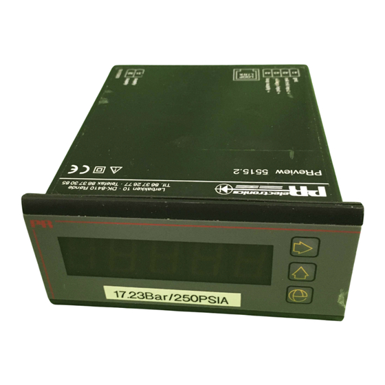
PR electronics PReview 5515 Bedienungsanleitung
Progr. lcd/led messgeraet

Verwandte Anleitungen für PR electronics PReview 5515


Inhaltszusammenfassung für PR electronics PReview 5515
- Seite 1 PR electronics A/S 5515 No. 5515V101-IN (0137) From ser. no. 970015001 Program. LCD / LED instrument Side Programmable LCD / LED indicator Page 15 Indicateur programmable LCD / LED Page 29 Program. LCD / LED Meßgerät Seite 43...
-
Seite 23: Schéma De Principe
PROGRAMMIERBARES LCD/LED MEßGERÄT PReview 5515 INHALTSVERZEICHNIS Warnung ........44 Sicherheitsregeln . -
Seite 24: Warnung
Installation, Montage und Demontage von Leitungen. Fehlersuche im Modul. Austausch von Batterien. Reparaturen des Moduls und Austausch von Sicherungen dürfen nur von PR electronics A/S vorgenommen werden. WARNUNG Zur Einhaltung der Sicherheitsabstände dürfen Module im SYSTEM 5500 mit zwei eingebauten Relaiseinheiten nicht sowohl an gefährliche und ungefährliche Spannung über die... -
Seite 25: Sicherheitsregeln
Händler vor Ort Kontakt aufnehmen. Sie können aber auch direkt geltend machen, welche ansonsten entsprechend der eingegangenen mit PR electronics GmbH, Bamlerstraße 92, D-45141 Essen, (Tel.: (0) 201 860 Verkaufsvereinbarungen existieren können. 6660) oder mit PR electronics A/S, Lerbakken 10, DK-8410 Rønde,... -
Seite 26: Einstellung Der Dip-Schalter
EINSTELLUNG DER DIP-SCHALTER UND PROGRAMMIERBARES DARSTELLUNG DER ANSCHLÜSSE DES LCD/LED MEßGERÄT 5515 SYSTEMS 5500 4-ziffriges LCD/LED Meßgerät Bild 1 zeigt, wie eine Änderung der DIP-Schalterkonfiguration möglich ist. PC-Programmierbar Außerdem ist der Anschluß an Opto Link 5901 im Modul 5511 dargestellt. Bild 2 zeigt den Anschlußstecker für die Programmierungseinheit Loop Link Galvanisch getrennt 3,75 kVAC 5905. -
Seite 27: Display
WTH-Eingang für Pt100/Ni100 in Temperaturbereichen gemäß den Normen IEC ELEKTRISCHE DATEN: 751 bzw. DIN 43760. Über PReset kann der Kabelwiderstand am 2-Leiter-Anschluß gemessen werden. Umgebungstemperatur: Kabelkompensation bei 3- oder 4-Leiter-Anschluß. (@: -20°C bis +60°C) Widerstandseingang für Ohmsche Widerstandsmessung. Max. Bereich 5000 Ω. Allgemeine Daten: Kabelkompensation bei 3- bzw. - Seite 28 Elektrische Daten - EINGANG Typ 5515-1: WTH / lin. R-Eingang: TE-Eingang: Min. Max. Min.Spanne Max. Nullpunktverschieb. Min. Max. Min. Norm Temp./Ω Temp./Ω Temp./Ω des gewählt. Maximalwertes Temperatur Temperatur Spanne 5 mV Pt100 -200°C +850°C 25°C Ni100 -60°C +250°C 25°C +400°C +1820°C 200°C IEC584...
-
Seite 29: Schleifendiagramm
Display-Aktualisierung ........ 2,5 x pro Sekunde BESTELLANGABEN: 5515 Rückwärtige Beleuchtung (LCD) ....Hellgrün Eingänge außerhalb des Eingangs- Anzeige Eingang Versorgung bereiches werden wie folgt angegeben: Nominelles Min. - 7% d. Meßspanne..In.LO 5515 LED WTH / TE / mV / R 115 VAC Nominelles Max. -
Seite 30: Blockdiagramm
BLOCKDIAGRAMM:... - Seite 31 Fax +45 86 37 30 85 firmaets kvalitetsstyringssystem i henhold til ISO 9001. Home page: www.prelectronics.com PR electronics A/S offers a wide range of analog and digital signal conditioning modules for industrial automation. The product range covers most functions within signal conditioning: Displays, power sup- plies, controllers, transmitters, isolation amplifiers and Ex barriers.